Analysis of Fusing - AVX
Analysis of Fusing - AVX
Analysis of Fusing - AVX
You also want an ePaper? Increase the reach of your titles
YUMPU automatically turns print PDFs into web optimized ePapers that Google loves.
TECHNICAL<br />
INFORMATION<br />
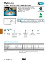
ANALYSIS OF FUSING TECHNOLOGY<br />
FOR<br />
TANTALUM CAPACITORS<br />
by Ian Salisbury<br />
<strong>AVX</strong>-Kyocera Group Company<br />
Paignton, Devon, TQ4 7ER<br />
England<br />
Tel: (0803) 528046<br />
Fax: (0803) 526223<br />
Abstract:<br />
Introduction <strong>of</strong> the fused capacitor, makes the<br />
failure mode <strong>of</strong> the device similar to a<br />
semiconductor. The fine wire fuse connected<br />
in series with the capacitor, similar to the<br />
wire bond used in the semiconductor, will<br />
open circuit under fault conditions and<br />
disconnect the capacitor from the circuit<br />
thereby failing safe.
ANALYSIS OF FUSING TECHNOLOGY FOR<br />
TANTALUM CAPACITORS<br />
by Ian Salisbury<br />
<strong>AVX</strong>-Kyocera Group Company<br />
Paignton, Devon, TQ4 7ER<br />
England<br />
Tel: (0803) 528046<br />
Fax: (0803) 526223<br />
Introduction<br />
An important aim for any electrical component,<br />
is that if it fails in operation, it will fail in a safe way,<br />
not causing burn damage to the equipment or cause<br />
electrical overload to the electrical circuit to which it is<br />
connected. This requirement is for any component such<br />
as Semiconductors, Resistors, Transformers and<br />
Capacitors.<br />
In the case <strong>of</strong> semiconductors most <strong>of</strong> these are<br />
constructed using wire bonding to connect from the<br />
customer termination to the chip face, and if the<br />
semiconductor junction fails the current capacity <strong>of</strong> this<br />
fine wire used to connect the semiconductor to the<br />
circuit, overloads and acts as a fuse which disconnects<br />
the semiconductor from the circuit.<br />
Resistors have a different failure mode. In most cases<br />
under steady state conditions, the resistor element will<br />
age to a higher resistance, thereby limiting the current.<br />
But if the voltage across the resistor is increased by a<br />
fault condition in the circuit then the resistor will carry<br />
more current and therefore dissipate more power, this<br />
can cause overheating, a burning <strong>of</strong> the area around<br />
the resistor.<br />
The Tantalum capacitor is similar to the resistor, in an<br />
overload condition. This can be due to the capacitor<br />
being connected the wrong way round in the circuit,<br />
which will apply reverse voltage to the capacitor. Excess<br />
voltage above its rated voltage, electrical stress due to<br />
high ripple currents or very high surge currents, can all<br />
induce a dielectric failure, and cause the capacitor to fail.<br />
The mode <strong>of</strong> failure is the same as a resistor. The<br />
capacitor will suffer a dielectric breakdown and act as a<br />
resistor with a low resistance in general between 3 ohms<br />
and 0.2 ohms, which will cause heating <strong>of</strong> the capacitor.<br />
The degree <strong>of</strong> heating will depend on the energy<br />
available from the power source. If sufficient energy is<br />
available, the capacitor may get very hot causing<br />
burning to the PCB.<br />
Introduction <strong>of</strong> the fused capacitor, makes the failure<br />
mode <strong>of</strong> the device similar to a semiconductor. The fine<br />
wire fuse connected in series with the capacitor, similar<br />
to the wire bond used in the semiconductor, will open<br />
circuit under fault conditions and disconnect the<br />
capacitor from the circuit thereby failing safe.<br />
CONSTRUCTION OF A TANTALUM CAPACITOR WITH FUSE<br />
The aim <strong>of</strong> this paper is to review the Tantalum<br />
capacitor, in the dielectric breakdown condition, and the<br />
various fusing methods used in the industry to fuse the<br />
capacitor.<br />
Why have the customers requested a fuse capacitor<br />
It would appear that it is for mixed reasons:<br />
- wrong way round<br />
- over voltage<br />
- a.c. ripple<br />
- circuit fault conditions<br />
- high energy with low impedance<br />
On assembly if the capacitor is connected into the<br />
circuit the wrong way round, it will be subjected to<br />
reverse voltage. The Tantalum capacitor can operate<br />
with a small reverse voltage, but will fail low resistance<br />
under larger reverse voltage stresses. It may operate<br />
for long periods before failing, therefore this incorrect<br />
assembly is not readily detectable on final test <strong>of</strong> the<br />
equipment, but when it does fail, it will fail low<br />
resistance. Depending on the energy available in the<br />
circuit to which the capacitor is connected, the capacitor<br />
can pass high currents and burn. A fused capacitor<br />
would ensure that under these conditions the capacitor<br />
will be disconnected from the circuit.<br />
If a capacitor is subject to a voltage in excess <strong>of</strong> the<br />
rated voltage, either by a transient spike or a continuous<br />
voltage overload then the capacitor may suffer a<br />
dielectric breakdown and become a low resistor. If<br />
sufficient power is available from the power source the
capacitor may get hot and can cause burning to the<br />
PCB, or it may take current and cause the power source<br />
to fail or overheat.<br />
If a capacitor is subjected to excess a.c. ripple current<br />
then dielectric heating occurs and this can cause the<br />
dielectric to rupture, and become low resistance, again<br />
causing heating and possible burning <strong>of</strong> the PCB to<br />
which it is mounted.<br />
In some <strong>of</strong> the d.c/d.c. converters, and motor control<br />
circuits high transient spikes can occur under fault or<br />
use conditions, then dielectric failure can occur again<br />
causing heating <strong>of</strong> the capacitor. The fitting <strong>of</strong> a higher<br />
voltage working capacitor or a fused capacitor will<br />
insure a safe operation.<br />
When a component fails, it can cause overstressing<br />
<strong>of</strong> other components. If it is considered that such a<br />
condition is likely to occur then fitting a fused capacitor<br />
would be a safe option.<br />
These five conditions are the main reasons why<br />
circuit designers have requested a fuse capacitor.<br />
Fuse Specification Requirements<br />
The assembly <strong>of</strong> a capacitor to a PCB by the<br />
equipment manufacturer is generally either by solder or<br />
conductive resin attachment. The temperature <strong>of</strong> the<br />
capacitor body can achieve 300c during an I/R reflow<br />
soldering process, therefore the construction <strong>of</strong> the<br />
capacitor, and the thermal design <strong>of</strong> a fuse has to be<br />
designed to withstand this temperature.<br />
When the capacitor is subjected to discharge and<br />
charge conditions at maximum rated voltage with<br />
minimum impedance, the fuse must be able to withstand<br />
large currents flowing in and out <strong>of</strong> the capacitor<br />
without blowing the fuse. The typical standard fusing<br />
characteristics in the industry are as shown,<br />
TIME IN SECONDS<br />
1000<br />
100<br />
TYPICAL DIFFERENT FUSE SPEED RATINGS<br />
TYPICAL TIME/CURRENT CHARACTERISTICS<br />
10<br />
1<br />
0.1<br />
LONG TIME-LAG<br />
VERY QUICK ACTING<br />
0.01<br />
1 10<br />
TIMES RATED CURRENT<br />
LONG TIME-LAG<br />
TIME-LAG<br />
MEDIUM TIME-LAG<br />
QUICK ACTING<br />
VERY QUICK ACTING<br />
The time delay fuse is used to allow large currents to<br />
flow for a short time, such as occurs in a television when<br />
it is switched on, but will fuse at a low current in a<br />
longer time interval. The disadvantage <strong>of</strong> this fuse is<br />
that the initial let-through current is high and could<br />
cause damage to the circuit in operation. The other end<br />
<strong>of</strong> the fusing is the very fast fuse which will cut the<br />
current flow in a short time, limiting the let-through<br />
current in turn limiting damage to the power source and<br />
other components in the circuit.<br />
Many applications for capacitors require a low ESR<br />
(equivalent series resistance). The fuse is a heat<br />
generating device. As current is passed through the fuse<br />
element, it heats up causing the fuse element to melt<br />
which then forms an open circuit, isolating the circuit<br />
from the power source. We have conflicting<br />
requirements. The fuse must have resistance to operate,<br />
but the fused capacitor must have low ESR. The circuit<br />
designer would like zero resistance. In general the fuse<br />
will add resistance <strong>of</strong> the order <strong>of</strong> 70 milohms to the<br />
ESR <strong>of</strong> the tantalum capacitor.<br />
The trend in the industry is for smaller component<br />
sizes. Typical dimensions are 7.3mm long, 3.2mm wide,<br />
known as the D case size; and 3.5mm long and 2.8mm<br />
wide, known as the B case size.<br />
Fuse Design Criteria<br />
The thermal rating <strong>of</strong> the small size <strong>of</strong> the capacitor<br />
depends on the method <strong>of</strong> mounting in the equipment.<br />
This can vary from 70c/ watt to 350c/ watt. The capacitor<br />
anode body can withstand 350c internal temperature for<br />
a short time before a risk <strong>of</strong> burning occurs.<br />
THERMAL IMPEDANCE GRAPH<br />
C CASE SIZE CAPACITOR BODY<br />
PACKAGE TEMPERATURE °C<br />
140<br />
120<br />
121 C/WATT<br />
100<br />
236 C/WATT<br />
80<br />
73 C/WATT<br />
40<br />
20<br />
10<br />
0<br />
0 0.1 0.2 0.3 0.4 0.5 0.6 0.7 0.8 0.9 1.0 1.1 1.2 1.3 1.4<br />
POWER IN UNIT CASE, DC WATTS<br />
PCB MAX Cu THERMAL<br />
PCB MIN Cu AIR GAP<br />
CAP IN FREE AIR<br />
If a breakdown <strong>of</strong> the Tantalum dielectric occurs,<br />
the failed capacitor resistance can vary from 3 ohms to<br />
0.2 ohms depending on the mode by which it failed.<br />
From the thermal rating and the failed resistance we<br />
can calculate the maximum current flowing to achieve a<br />
temperature <strong>of</strong> 350c.<br />
For 350c /watt and a failed resistance <strong>of</strong> 3 ohms<br />
Isq = watts/resistance = 1/3 = 0.33<br />
I = 0.57 amps<br />
For 350c/watt and a failed resistance <strong>of</strong> 0.2 ohms<br />
Isq = watts/resistance = 1/0.2 = 5<br />
I = 2.2 amps<br />
For 70c/watt and a failed resistance <strong>of</strong> 3 ohms<br />
Isq = watts/resistance = 5/3 = 1.66<br />
I = 1.29 amps
For 70c/watt and a failed resistance <strong>of</strong> 0.2 ohms<br />
Isq = watts/resistance = 5/0.2 = 25<br />
I = 5.0 amps<br />
FUSED CAPACITOR THERMAL/ELECTRICAL<br />
TEMPERATURE RISE, PACKAGE RATING WATTS/C<br />
WITH VARIOUS FAILED RESISTANCE VALUES<br />
from the capacitor body, it will disconnect the capacitor<br />
from the circuit.<br />
LOW MELTING POINT FUSE WIRE STRUCTURE<br />
From these calculations the current which can cause<br />
the capacitor to overheat from 0.57 to 5 amps, depending<br />
on how the capacitor is mounted (which will effect its<br />
thermal rating), and the type <strong>of</strong> failure, which controls<br />
the failed resistance.<br />
When a Tantalum capacitor manufacturer supplies a<br />
capacitor to the industry, they do not know under what<br />
conditions it is to be used, therefore the design <strong>of</strong> the<br />
fuse in the capacitor has to cater for all conditions.<br />
From the above discussion the main aim <strong>of</strong> a fused<br />
capacitor is:<br />
1. Limit the temperature <strong>of</strong> the capacitor body to stop<br />
burning under a fault condition.<br />
2. Disconnect the capacitor from the circuit as quickly<br />
as possible to reduce the risk <strong>of</strong> damage to the power<br />
source and other circuit elements.<br />
3. To withstand the solder mounting at 300c and other<br />
thermal stresses experienced in assembly and operation<br />
<strong>of</strong> the equipment.<br />
DIFFERENT FUSE ELEMENT CONCEPTS<br />
LOW MELTING POINT FUSE ELEMENTS -<br />
APPROX 300C<br />
HIGH TEMPERATURE SINGLE METAL<br />
WIRE OR TAPE - 1000C<br />
HIGH TEMPERATURE TWO METAL WIRE<br />
650 to 1000C<br />
HIGH TEMPERATURE WIRE CLAD WITH<br />
LOW MELTING POINT METAL<br />
Low Melting Point Fuse Elements<br />
The clear requirement is the thermal limit <strong>of</strong> 350c for<br />
the capacitor element. One way is to place inside the<br />
capacitor body a low melting point link close to the<br />
capacitor element, and wire it electrical in series with<br />
the capacitor, so when the fuse link melts due to the heat<br />
The use <strong>of</strong> a solder wire which melts above 300c, (so<br />
that it will not degrade during the component solder<br />
reflow), has the advantage that it will become unstable<br />
with temperature above the melting point. In domestic<br />
fusing applications when this type <strong>of</strong> fuse element is<br />
used, the construction is such that the fuse element is<br />
suspended in free air, so that when the fuse wire melts it<br />
can fall into the free space, to give a clean electrical<br />
break. Due to the small size <strong>of</strong> the Tantalum capacitor<br />
which requires a very small fuse and the method <strong>of</strong><br />
manufacture, adding a free space around the fuse<br />
element to date has not been possible. Therefore, the<br />
material surrounding the fuse element has to degrade to<br />
form a space, or absorb the melted metal, or the solder<br />
has to be converted into an insulating oxide. To date the<br />
reported performance is that with the solder wire size<br />
available <strong>of</strong> 0.1mm dia. with 5 amps flowing, there is<br />
sufficient energy to obtain an acceptable fusing speed,<br />
but at low currents the fuse will take a long time<br />
to blow due to the molten metal being absorbed by<br />
the surrounding encapsulation and is reported to<br />
be inconsistent in interrupting the current flow.<br />
Fuse Wire High Melting Point<br />
A fuse design using a wire <strong>of</strong> high melting point will<br />
not sense the critical temperature <strong>of</strong> 300 to 350c. In<br />
order to fully protect the capacitor, it will have to set the<br />
fusing conditions such that it will in the worst case <strong>of</strong><br />
high failed resistance, and worst case thermal<br />
impedance <strong>of</strong> the capacitor. In the worst case reviewed<br />
earlier in the paper this could be as low as 0.57 amp with<br />
failed resistance <strong>of</strong> 3 ohms. Tantalum capacitors are<br />
marketed with this type <strong>of</strong> fuse wire. Some <strong>of</strong> the fuses<br />
contain a fuse element <strong>of</strong> two materials which have an<br />
exothermic reaction at about 650c. This results in a high<br />
temperature which generates its own cavity allowing<br />
the alloy to disperse, giving a clean electrical break.<br />
This will only occur if sufficient energy is dissipated in<br />
the fuse.
CAPACITOR WITH HIGH TEMP ELECTRICAL/FUSE<br />
TEMPERATURE RISE, PACKAGE RATING WATTS/C,<br />
WITH TYPICAL HIGH TEMPERATURE FUSE<br />
PACKAGE TEMPERATURE C<br />
400<br />
FUSE TIME SECS<br />
35<br />
BURN RISK AREA<br />
350<br />
300<br />
250<br />
200<br />
150<br />
100<br />
50<br />
30<br />
25<br />
20<br />
15<br />
10<br />
5<br />
0<br />
0<br />
0 0.5 1 1.5 2 2.5 3 3.5<br />
FUSE N2670<br />
CURRENT IN AMPS<br />
350C/WATTS - 3.0 OHMS<br />
350C/WATTS - 0.2 OHMS<br />
70C/WATTS - 3.0 OHMS<br />
70C/WATTS - 0.2 OHMS WITH VARIOUS FAILED RESISTANCE VALUES<br />
The disadvantage <strong>of</strong> this type <strong>of</strong> fuse is that it does<br />
not sense temperature, and if it is set with a very low<br />
fuse setting it has to be a delay fuse, in order that the<br />
fuse will not open circuit under capacitor charge and<br />
discharge conditions. This fuse design is a compromise<br />
between setting the fuse current to withstand the<br />
charge/discharge, and at the same time stop the<br />
capacitor burning, under the worst case condition <strong>of</strong><br />
high failed resistance. This will require a fuse setting<br />
about 0.5 amps.<br />
<strong>AVX</strong> Binary Fuse Construction<br />
This type <strong>of</strong> fuse design comprises a two metal<br />
system, the innercore <strong>of</strong> the fuse wire is a high<br />
temperature metal, with the outer cladding <strong>of</strong> a low<br />
melting metal. When the fuse element reaches a<br />
temperature <strong>of</strong> 320c, the outer cladding melts and<br />
exposes the inner core. This action changes the fuse<br />
characteristics to a low current blow fuse, which fuses at<br />
a temperature <strong>of</strong> above 1000c creating a cavity and<br />
giving a clean, fast electrical open circuit.<br />
The advantage <strong>of</strong> this type <strong>of</strong> fuse is that it is a<br />
thermal and a low current electrical fuse.<br />
CAPACITOR + BINARY THERMAL/ELECTRICAL<br />
TEMPERATURE RISE, PACKAGE RATING WATTS/C,<br />
WITH BINARY FUSE<br />
PACKAGE TEMPERATURE C<br />
400<br />
BURN RISK AREA<br />
350<br />
REMOVED<br />
300<br />
FUSE<br />
THERMAL LIMIT<br />
250<br />
200<br />
BINARY FUSE<br />
BLOW CURVE AT 320°C<br />
150<br />
100<br />
50<br />
BINARY FUSE<br />
BLOW AMPS AT 25°C<br />
FUSE TIME SECS<br />
35<br />
30<br />
25<br />
20<br />
15<br />
10<br />
0<br />
0<br />
0 0.5 1 1.5 2 2.5 3 3.5<br />
FUSE N2670 AT 25°C<br />
CURRENT IN AMPS<br />
FUSE N2570 AT 300°C<br />
350C/WATTS - 3.0 OHMS<br />
350C/WATTS - 0.2 OHMS<br />
70C/WATTS - 3.0 OHMS<br />
70C/WATTS - 0.2 OHMS WITH VARIOUS FAILED RESISTANCE VALUES<br />
It can be seen from the graph, the two fusing curves<br />
one at 25c the other at 320c, this demonstrates the<br />
change in sensitivity once the fuse element has achieved<br />
320c. The fuse can therefore be set, to a fuse blow rating<br />
well away from the charge/discharge currents, over the<br />
capacitor operating temperature range, yet limit the<br />
fault current at 25c to a low value when the capacitor<br />
fails with low resistance.<br />
5<br />
If the capacitor failed high resistance, the capacitor<br />
will get hot, then the fuse will change sensitivity at 320c,<br />
and the fuse will blow to disconnect the capacitor from<br />
the circuit.<br />
TAJ B,C,D FUSED TANTALUM CAPACITORS<br />
PACKAGE TEMPERATURE TO CURRENT IN AMPS<br />
CAPACITOR MOUNTED ONTO PCB 1 INCH SQ<br />
The graph <strong>of</strong> TAJ B, C & B fused tantalum, give<br />
results obtained during fusing trials, in all these cases<br />
the short circuit current was sufficient to heat the<br />
capacitor, but not electrical activate the fuse, the fuse<br />
was activated when the capacitor element achieved<br />
320c, and it can be seen from the graph package<br />
temperature was 240c.<br />
Summary<br />
1. It must be remembered by the circuit designer,<br />
that with any fuse system there must be sufficient<br />
energy designed in and available to blow the fuse, under<br />
fault conditions.<br />
2. The choice <strong>of</strong> fuse technology is important, for<br />
example:<br />
a. With a Non-thermal fuse, if the capacitor fails, with<br />
a failed resistance <strong>of</strong> 3 ohms, and the fuse is set to<br />
blow at 2 amps, then the voltage across the<br />
capacitor has to be in excess <strong>of</strong> 6 volts, and the<br />
power supply has to be capable <strong>of</strong> activating the<br />
fuse. Therefore, the circuit designer has to ensure<br />
that his circuit is capable <strong>of</strong> supplying the energy<br />
to blow the fuse.<br />
b. The Thermal electrical fuse, which is either a low<br />
melting point metal or Binary fuse, will start to<br />
activate the approx 300c, and the electrical energy<br />
will cause the fuse to become open circuit.<br />
The low melting point fuse will be less sensitive at<br />
low currents approx 0.7 amps, and is reported to have a<br />
slow blow, and inconsistent blow rate.<br />
The Binary fuse will give a clean blow rate at low<br />
currents <strong>of</strong> 0.6 amps, and or with a fuse temperature<br />
<strong>of</strong> 330c.<br />
3. If the circuit electrical loading conditions are in the<br />
low current area then it is recommended to consult the<br />
capacitor manufacturer on his best product for the<br />
application.
NOTICE: Specifications are subject to change without notice. Contact your nearest <strong>AVX</strong> Sales Office for the latest specifications. All statements, information and data<br />
given herein are believed to be accurate and reliable, but are presented without guarantee, warranty, or responsibility <strong>of</strong> any kind, expressed or implied. Statements<br />
or suggestions concerning possible use <strong>of</strong> our products are made without representation or warranty that any such use is free <strong>of</strong> patent infringement and are not<br />
recommendations to infringe any patent. The user should not assume that all safety measures are indicated or that other measures may not be required. Specifications<br />
are typical and may not apply to all applications.<br />
© <strong>AVX</strong> Corporation
USA<br />
EUROPE<br />
ASIA-PACIFIC<br />
<strong>AVX</strong> Myrtle Beach, SC<br />
Corporate Offices<br />
Tel: 843-448-9411<br />
FAX: 843-626-5292<br />
<strong>AVX</strong> Northwest, WA<br />
Tel: 360-699-8746<br />
FAX: 360-699-8751<br />
<strong>AVX</strong> North Central, IN<br />
Tel: 317-848-7153<br />
FAX: 317-844-9314<br />
<strong>AVX</strong> Mid/Pacific, MN<br />
Tel: 952-974-9155<br />
FAX: 952-974-9179<br />
<strong>AVX</strong> Southwest, AZ<br />
Tel: 480-539-1496<br />
FAX: 480-539-1501<br />
<strong>AVX</strong> South Central, TX<br />
Tel: 972-669-1223<br />
FAX: 972-669-2090<br />
<strong>AVX</strong> Southeast, NC<br />
Tel: 919-878-6223<br />
FAX: 919-878-6462<br />
<strong>AVX</strong> Canada<br />
Tel: 905-564-8959<br />
FAX: 905-564-9728<br />
Contact:<br />
<strong>AVX</strong> Limited, England<br />
European Headquarters<br />
Tel: ++44 (0) 1252 770000<br />
FAX: ++44 (0) 1252 770001<br />
<strong>AVX</strong> S.A., France<br />
Tel: ++33 (1) 69.18.46.00<br />
FAX: ++33 (1) 69.28.73.87<br />
<strong>AVX</strong> GmbH, Germany - <strong>AVX</strong><br />
Tel: ++49 (0) 8131 9004-0<br />
FAX: ++49 (0) 8131 9004-44<br />
<strong>AVX</strong> GmbH, Germany - Elco<br />
Tel: ++49 (0) 2741 2990<br />
FAX: ++49 (0) 2741 299133<br />
<strong>AVX</strong> srl, Italy<br />
Tel: ++390 (0)2 614571<br />
FAX: ++390 (0)2 614 2576<br />
<strong>AVX</strong> Czech Republic, s.r.o.<br />
Tel: ++420 (0)467 558340<br />
FAX: ++420 (0)467 558345<br />
<strong>AVX</strong>/Kyocera, Singapore<br />
Asia-Pacific Headquarters<br />
Tel: (65) 258-2833<br />
FAX: (65) 350-4880<br />
<strong>AVX</strong>/Kyocera, Hong Kong<br />
Tel: (852) 2-363-3303<br />
FAX: (852) 2-765-8185<br />
<strong>AVX</strong>/Kyocera, Korea<br />
Tel: (82) 2-785-6504<br />
FAX: (82) 2-784-5411<br />
<strong>AVX</strong>/Kyocera, Taiwan<br />
Tel: (886) 2-2696-4636<br />
FAX: (886) 2-2696-4237<br />
<strong>AVX</strong>/Kyocera, China<br />
Tel: (86) 21-6249-0314-16<br />
FAX: (86) 21-6249-0313<br />
<strong>AVX</strong>/Kyocera, Malaysia<br />
Tel: (60) 4-228-1190<br />
FAX: (60) 4-228-1196<br />
Elco, Japan<br />
Tel: 045-943-2906/7<br />
FAX: 045-943-2910<br />
Kyocera, Japan - <strong>AVX</strong><br />
Tel: (81) 75-604-3426<br />
FAX: (81) 75-604-3425<br />
Kyocera, Japan - KDP<br />
Tel: (81) 75-604-3424<br />
FAX: (81) 75-604-3425<br />
A KYOCERA GROUP COMPANY<br />
http://www.avxcorp.com<br />
S-AFTT00M301-R


