Rankine Cycle Consider a coal-fired steam power plant that ...
Rankine Cycle Consider a coal-fired steam power plant that ...
Rankine Cycle Consider a coal-fired steam power plant that ...

You also want an ePaper? Increase the reach of your titles
YUMPU automatically turns print PDFs into web optimized ePapers that Google loves.
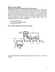
ME 354 Tutorial, Week#5 – - <strong>Rankine</strong> <strong>Cycle</strong><br />
<strong>Consider</strong> a <strong>coal</strong>-<strong>fired</strong> <strong>steam</strong> <strong>power</strong> <strong>plant</strong> <strong>that</strong> produces 300MW of electric <strong>power</strong>. The<br />
<strong>power</strong> <strong>plant</strong> operates on a simple ideal <strong>Rankine</strong> cycle with turbine inlet conditions of 5<br />
MPa and 450°C and a condenser pressure of 25 kPa. The <strong>coal</strong> used has a heating value<br />
(energy released when the fuel is burned) of 29,300kJ/kg. Assuming <strong>that</strong> 75 percent of<br />
this energy is transferred to the <strong>steam</strong> in the boiler and <strong>that</strong> the electric generator has an<br />
efficiency of 96 percent, determine:<br />
a) the overall <strong>plant</strong> efficiency (the ratio of net electric <strong>power</strong> output to the energy<br />
input as fuel)<br />
b) the required rate of <strong>coal</strong> supply<br />
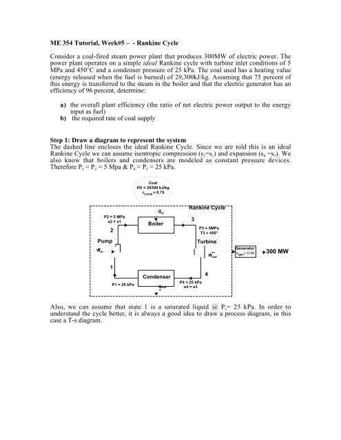
Step 1: Draw a diagram to represent the system<br />
The dashed line encloses the ideal <strong>Rankine</strong> <strong>Cycle</strong>. Since we are told this is an ideal<br />
<strong>Rankine</strong> <strong>Cycle</strong> we can assume isentropic compression (s 2 =s 1 ) and expansion (s 4 =s 3 ). We<br />
also know <strong>that</strong> boilers and condensers are modeled as constant pressure devices.<br />
Therefore P 3 = P 2 = 5 Mpa & P 4 = P 1 = 25 kPa.<br />
Coal<br />
HV = 29300 kJ/kg<br />
η<br />
comb = 0.75<br />
P2 = 5 MPa<br />
s2 = s1<br />
2<br />
Qin<br />
Boiler<br />
<strong>Rankine</strong> <strong>Cycle</strong><br />
3<br />
P3 = 5MPa<br />
T3 = 450°<br />
Pump<br />
W in<br />
Turbine<br />
W out<br />
Generator<br />
η<br />
gen= 0.96<br />
300 MW<br />
1<br />
P1 = 25 kPa<br />
Condenser<br />
Qout<br />
P4 = 25 kPa<br />
s4 = s3<br />
4<br />
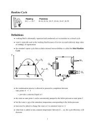
Also, we can assume <strong>that</strong> state 1 is a saturated liquid @ P 1 = 25 kPa. In order to<br />
understand the cycle better, it is always a good idea to draw a process diagram, in this<br />
case a T-s diagram.
T<br />
W in<br />
1<br />
2<br />
s 1<br />
Q in<br />
Q out<br />
s<br />
P = 5 MPa<br />
3<br />
W out<br />
4<br />
s 3<br />
P = 25 kPa<br />
Step 2: Prepare a property table<br />
Preparing a property table becomes increasingly important when solving cycle-based<br />
problems.<br />
Property<br />
State T [°C] P [kPa] h [kJ/kg] s [kJ/kg*K] v [m 3 /kg]<br />
1 (sat liq) 25<br />
Step 3: State your assumptions<br />
Assumptions:<br />
1) SSSF (steady state/steady flow)<br />
2) ∆ke, ∆pe ≈ 0<br />
3) isentropic compression (1→ 2) / isentropic expansion (3→ 4)<br />
4) state 1 is a saturated liquid & incompressible substance<br />
5) constant pressure across boiler / constant pressure across condenser<br />
Step 4: Calculations<br />
Part a)<br />
We are asked to find the overall <strong>plant</strong> efficiency of converting the chemical energy stored<br />
in the <strong>coal</strong> into electricity. Our overall efficiency will be based on:<br />
1) How efficiently we can convert <strong>coal</strong> into heat energy transferred into the boiler<br />
(η comb = 0.75)<br />
2) How efficiently the ideal <strong>Rankine</strong> <strong>Cycle</strong> operates in converting the heat input to<br />
• •<br />
the boiler into net work at the turbine shaft (η th = W net / Q )<br />
in<br />
3) How efficiently a generator can use the net shaft work of the turbine to generate<br />
electricity (η gen = 0.96)<br />
This is expressed mathematically in Eq1.<br />
2 5000 s 1<br />
v 1<br />
3 450.00 5000<br />
4 25 s 3
η = η η η<br />
(Eq1)<br />
overall<br />
Since we know the values of the first and third efficiencies, the problem is reduced to<br />
finding the thermal efficiency of the cycle as expressed in Eq2.<br />
comb<br />
th<br />
gen<br />
η<br />
th<br />
•<br />
W net<br />
=<br />
•<br />
Q<br />
in<br />
W<br />
=<br />
• •<br />
out −W<br />
in<br />
•<br />
Q<br />
in<br />
(Eq2)<br />
To find the work out (turbine 3 → 4), we will draw a control volume <strong>that</strong> encloses the<br />
<strong>steam</strong> in the turbine as shown below.<br />
3<br />
Turbine<br />
W out<br />
Writing an energy balance on the turbine from state 3 → 4 using the assumption of ∆ke,<br />
∆pe ≈ 0 and SSSF we obtain Eq3.<br />
4<br />
W<br />
• out = m<br />
•<br />
(Eq3)<br />
( h − )<br />
H 2O<br />
3<br />
h4<br />
To find the work in (pump 1 → 2), we will draw a control volume <strong>that</strong> encloses the water<br />
in the pump as shown below.<br />
2<br />
Pump<br />
W in<br />
1<br />
Writing an energy balance on the pump from state 1 → 2 using the assumption of ∆ke,<br />
∆pe ≈ 0 and SSSF we obtain Eq4.<br />
W<br />
• in = m<br />
•<br />
(Eq4)<br />
( h − )<br />
H 2O<br />
2<br />
h 1<br />
To find the energy transfer as heat in (boiler 2 → 3), we will draw a control volume <strong>that</strong><br />
encloses the water/<strong>steam</strong> in the boiler as shown below.
2<br />
Q<br />
in<br />
Boiler<br />
3<br />
Writing an energy balance on the boiler from state 2 → 3 using the assumption of ∆ke,<br />
∆pe ≈ 0 and SSSF we obtain Eq5.<br />
Q<br />
• = m<br />
•<br />
(Eq5)<br />
in<br />
( h − )<br />
H 2O<br />
3<br />
h2<br />
Substituting Eq3, Eq4, and Eq5 into Eq2 to obtain Eq6<br />
η<br />
th<br />
• •<br />
W out −W<br />
in<br />
=<br />
•<br />
Q<br />
in<br />
( h<br />
=<br />
3<br />
− h4<br />
) − ( h2<br />
− h1<br />
)<br />
( h − h )<br />
3<br />
2<br />
= 1−<br />
( h4<br />
− h1<br />
) qout<br />
= 1−<br />
( h3<br />
− h2<br />
) qin<br />
(Eq6)<br />
Note: We could have just jumped from Eq2 to Eq6 and written the energy balances for<br />
the condenser and boiler.<br />
Eq6 shows <strong>that</strong> we must determine the enthalpy at each state point to calculate the<br />
thermal efficiency. We will start at state 1. Since we know <strong>that</strong> state 1 is saturated liquid<br />
H 2 O @ P= 25kPa, we can use Table A-5 to determine the properties.<br />
Table A-5 @ P= 25kPa<br />
h 1 = h f@P=25kPa = 271.93 kJ/kg<br />
s 1 = s f@P=25kPa = 0.8931 kJ/kg*K<br />
v 1 = v f@P=25kPa = 0.001020 m 3 /kg<br />
To find the enthalpy of state 2, we will make use of Eq 6-53 (from text) to express the<br />
reversible work in as shown in Eq7. We treat the liquid H 2 O as an incompressible<br />
substance (v 1 = v 2 = v)<br />
W<br />
• in = m<br />
•<br />
H 2O<br />
v( P − P1)<br />
(Eq7)<br />
Combining Eq7 with Eq4, and isolating for h 2 we obtain Eq8.<br />
2<br />
•<br />
•<br />
H 2 O<br />
) +<br />
m<br />
( h2<br />
− h1<br />
) = mH<br />
2O<br />
v( P2<br />
− P1<br />
) → h2<br />
= v(<br />
P2<br />
− P1<br />
h1<br />
(Eq8)<br />
Substituting the known values into Eq8, we can determine h 2 .<br />
→ h = (0.001020)(5000 − 25) + 271.93 = 5.074 271.93 =277 kJ/kg<br />
2<br />
+<br />
Since we know the temperature (450°C) and pressure (5 MPa) at state 3, we can use the<br />
<strong>steam</strong> table to find the properties. Looking in Table A-5 @ P= 5 MPa we see the
corresponding saturated temperature is 263.99°C. Since the temperature is greater than<br />
the saturated temperature we must have superheated <strong>steam</strong>. We can make use of Table A-<br />
6 @ P= 5 MPa & T = 450°C to find the properties at state 3.<br />
Table A-6 @ P= 5 MPa, T=450°C<br />
h 3 = 3316.2 kJ/kg<br />
s 3 = 6.8186 kJ/kg*K<br />
To find the enthalpy at state 4 we will use the fact <strong>that</strong> the expansion of the <strong>steam</strong> by<br />
turbine from state 3→4 is isentropic.<br />
→ s 4 = 6.8186 kJ/kg*K<br />
Looking in Table A-5 using s 4 with the known pressure P 4 = 25kPa, we see <strong>that</strong> s 4 is in<br />
between the saturated liquid value, s f , and the saturated vapor value, s g . We can now<br />
determine the quality of the saturated liquid-vapor mixture at state 4.<br />
x<br />
s<br />
− s<br />
6.8186 − 0.8931<br />
=<br />
6.9383<br />
4 f<br />
4<br />
=<br />
=<br />
s<br />
fg<br />
0.854<br />
The enthalpy at state 4 can be determined by interpolating using the quality between the<br />
saturated liquid and vapor states @ P=25 kPa in Table A-5.<br />
Table A-5 @ P= 25kPa<br />
→ h 4 = h f@P=25kPa + xh fg@P=25kPa = (271.93) +(0.854)(2346.3)=2275.74 kJ/kg<br />
Substituting in the enthalpies into Eq6.<br />
( h − h1<br />
)<br />
( h − h )<br />
( 2275.74 − 271.93)<br />
= 1<br />
( 3316.2 − 277) 3039. 2<br />
4<br />
2003.47<br />
→ η = 1−<br />
= 1−<br />
− = 0.341<br />
th<br />
Substituting this into Eq1<br />
3<br />
2<br />
η η η η = ( 0.75)( 0.341)( 0.96)<br />
=0.246=24.6% Answer a)<br />
overall<br />
=<br />
comb th gen<br />
Part b)<br />
We need to find the required rate of <strong>coal</strong> supply. We are given <strong>that</strong> <strong>coal</strong> has a heating<br />
value of 29300kJ/kg and <strong>that</strong> 75 percent of the energy from combusting the <strong>coal</strong> is<br />
transferred to the boiler. We can make use of the fact <strong>that</strong> the overall efficiency is the<br />
ratio of net electric <strong>power</strong> output, E • electric , to the energy input as fuel, E • <strong>coal</strong> . This is<br />
expressed in Eq9.<br />
η<br />
•<br />
•<br />
E<br />
•<br />
electric E electric<br />
overall<br />
= → E <strong>coal</strong> =<br />
(Eq9)<br />
•<br />
E<br />
η<br />
<strong>coal</strong><br />
overall
The energy input as fuel can be expressed in terms of the heating value of <strong>coal</strong> and the<br />
rate of <strong>coal</strong> supply as shown in Eq10.<br />
•<br />
E <strong>coal</strong><br />
•<br />
= HV<strong>coal</strong><br />
m <strong>coal</strong><br />
(Eq10)<br />
Substituting Eq10 into Eq9, we obtain and expression for the rate of <strong>coal</strong> supply as shown<br />
in Eq11.<br />
•<br />
<strong>coal</strong><br />
m<br />
•<br />
E electric<br />
= (Eq11)<br />
HV<strong>coal</strong>ηoverall<br />
Substituting in the net electric <strong>power</strong> output (300MW), the heating value of <strong>coal</strong> (29300<br />
kJ/kg), and the overall efficiency (0.264).<br />
•<br />
300000<br />
m <strong>coal</strong> =<br />
=41.62 kg/s = 149.84 t/h Answer b)<br />
( 29300)( 0.246)<br />
Step 5: Concluding Statement and Remarks<br />
The overall <strong>plant</strong> efficiency was found to be 24.6%. The required rate of <strong>coal</strong> supply<br />
was found to be 149.84 t/h.