ncr/doc/RealPOS/7455/Technical_Manuals/7455_Re... - Alsys Data
ncr/doc/RealPOS/7455/Technical_Manuals/7455_Re... - Alsys Data
ncr/doc/RealPOS/7455/Technical_Manuals/7455_Re... - Alsys Data

Create successful ePaper yourself
Turn your PDF publications into a flip-book with our unique Google optimized e-Paper software.
Chapter 2: Hardware Installation 2-5<br />
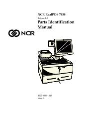
Identifying the Cable Connectors<br />
The following illustration identifies each of the cable connectors. <strong>Re</strong>fer<br />
to the sections following the illustration for specific instructions on<br />
installing each peripheral. After installing the peripheral and LAN<br />
cables, replace the cable cover and tighten the thumbscrew.<br />
Note: 12VDC output on the powered RS-232 ports.<br />
VGA LAN USB RS-232/A RS-232/B<br />
Powered<br />
Mouse<br />
Power<br />
Infared Speaker<br />
Speaker Out<br />
RS-232/D<br />
RS-232/C<br />
Powered<br />
Keyboard<br />
Scanner Mic Parallel<br />
(Customer Display)<br />
Cash<br />
Drawer<br />
18367<br />
Caution: The wedge scanner port on the POS daughterboard and the<br />
Ethernet port on the processor board are the same type of connector.<br />
The Ethernet cable and port are labeled with the PC99 standard<br />
connector color (black) for Ethernet devices to reduce the risk of<br />
plugging these devices incorrectly. If an Ethernet hub is connected to<br />
the powered scanner port, the Ethernet hub will be permanently<br />
damaged.<br />
Note: The scanner port comes with a blank connector plug installed.<br />
This plug must be removed before a device can be connected to the<br />
scanner port.