ncr/doc/RealPOS/7455/Technical_Manuals/7455_Re... - Alsys Data
ncr/doc/RealPOS/7455/Technical_Manuals/7455_Re... - Alsys Data
ncr/doc/RealPOS/7455/Technical_Manuals/7455_Re... - Alsys Data

Create successful ePaper yourself
Turn your PDF publications into a flip-book with our unique Google optimized e-Paper software.
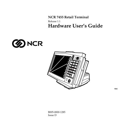
NCR <strong>7455</strong> <strong>Re</strong>tail Terminal<br />
<strong>Re</strong>lease 1.1<br />
Hardware User’s Guide<br />
7<br />
8<br />
9<br />
4<br />
5<br />
6<br />
1<br />
2<br />
3<br />
0<br />
1842<br />
B005-0000-1285<br />
Issue D
The products described in this book are licensed products of NCR Corporation.<br />
NCR is a registered trademark of NCR Corporation.<br />
Microtouch is a registered trademark of 3M.<br />
Sound Blaster is a registered trademark of Creative Technology Ltd. in the United States and/or other<br />
countries.<br />
Intel, Pentium, and Celeron are registered trademarks of Intel Corporation.<br />
Microsoft, Windows, and Windows NT are either trademarks or registered trademarks of Microsoft<br />
Corporation in the United States and/or other countries.<br />
DiskOnChip is a trademark or registered trademark of M-Systems in the United States.<br />
Novell and Netware are either registered trademarks or trademarks of Novell, Inc. in the United States and<br />
other countries.<br />
UNIX is a registered trademark of The Open Group in the United States and other countries.<br />
Ghost is a registered trademark of Symantec Corporation in the United States and other countries.<br />
It is the policy of NCR Corporation (NCR) to improve products as new technology, components, software,<br />
and firmware become available. NCR, therefore, reserves the right to change specifications without prior<br />
notice.<br />
All features, functions, and operations described herein may not be marketed by NCR in all parts of the<br />
world. In some instances, photographs are of equipment prototypes. Therefore, before using this <strong>doc</strong>ument,<br />
consult with your NCR representative or NCR office for information that is applicable and current.<br />
To maintain the quality of our publications, we need your comments on the accuracy, clarity, organization,<br />
and value of this book.<br />
Address correspondence to:<br />
Manager, Information Products<br />
NCR Corporation<br />
2651 Satellite Blvd.<br />
Duluth, GA 30096<br />
Copyright © 2002<br />
By NCR Corporation<br />
Dayton, Ohio U.S.A.<br />
All Rights <strong>Re</strong>served
i<br />
Safety Warnings<br />
Preface<br />
Audience<br />
This book is written for hardware installer/service personnel, system<br />
integrators, and field engineers.<br />
Notice: This <strong>doc</strong>ument is NCR proprietary information and is not to<br />
be disclosed or reproduced without consent.<br />
This equipment is intended for use with an IT power system with a line-toline<br />
voltage of 240 V or less.<br />
Fuse <strong>Re</strong>placement<br />
Caution: For continued protection against risk of fire, replace only<br />
with the same type and ratings of fuse.<br />
Attention: Pour prévenir et vous protéger contre un risque de feu,<br />
remplacer la fusible avec une autre fusible de même type, seulement.<br />
Power Supply Cord Used as Disconnect Means<br />
Caution: The power supply cord is used as the main disconnect<br />
device. Ensure that the socket outlet is located/installed near the<br />
equipment and is easily accessible.<br />
Attention: Le cordon d'alimentation est utilisé comme interrupteur<br />
général. La prise de courant doit être située ou installée å proximité du<br />
matériel et être facile d'accés.<br />
Warning: DO NOT connect or disconnect the transaction printer<br />
while the terminal is powered on. This can result in system or printer<br />
damage.
ii<br />
Lithium Battery Warning<br />
Caution: Danger of explosion if battery is incorrectly replaced.<br />
<strong>Re</strong>place only with the same or equivalent type as recommended by the<br />
manufacturer. Discard used batteries according to the manufacturer’s<br />
instructions.<br />
Attention: Il y a danger d'explosion s'il y a remplacement incorrect de<br />
la batterie. <strong>Re</strong>mplacer uniquement avec une batterie du même type ou<br />
d'un type recommandé par le constructeur. Mettre au rébut les<br />
batteries usagées conformément aux instructions du fabricant.<br />
Peripheral Usage<br />
This terminal should only be used with peripheral devices that are<br />
certified by the appropriate safety agency for the country of installation<br />
(UL, CSA, TUV, VDE) or those which are recommended by NCR<br />
Corporation.<br />
<strong>Re</strong>ferences<br />
Environmental Consciousness<br />
NCR is demonstrating its concern for the environment by designing an<br />
intelligent power management system into this terminal that operates<br />
efficiently whether the system is in a stand-alone or network<br />
environment.<br />
• NCR <strong>7455</strong> <strong>Re</strong>tail Terminal Hardware Service Guide<br />
(B005-0000-1339)<br />
• NCR <strong>7455</strong> <strong>Re</strong>tail Terminal Site Preparation Guide<br />
(B005-0000-1286)<br />
• NCR FitClient User’s Guide<br />
(B005-0000-1235)<br />
• NCR <strong>7455</strong> <strong>Re</strong>tail Terminal Parts Identification Manual<br />
(B005-0000-1287)
iii<br />
Table of Contents<br />
Chapter 1: Product Overview<br />
Introduction .................................................................. 1-1<br />
Serial Number/Model Number Label........................ 1-2<br />
Hardware Modules ...................................................... 1-3<br />
Base Unit................................................................. 1-3<br />
Hardware Options ................................................. 1-4<br />
System Configuration Diagram................................... 1-7<br />
Hardware Module Descriptions.................................. 1-8<br />
Processor Board...................................................... 1-8<br />
Processor/Chip Set ............................................ 1-8<br />
Video Subsystem................................................ 1-8<br />
Ethernet 10/100Base-T LAN<br />
Communications................................................ 1-9<br />
Wireless LAN Communications ..................... 1-10<br />
Universal Serial Bus......................................... 1-11<br />
Serial Ports........................................................ 1-11<br />
Hardware Monitor........................................... 1-12<br />
PCI Expansion Header .................................... 1-12<br />
IDE Header....................................................... 1-12<br />
Audio ................................................................ 1-12<br />
Magnetic Stripe <strong>Re</strong>ader ................................... 1-13<br />
Optional Touch Screen Controller .................. 1-13<br />
Processor Board Connectors ........................... 1-14<br />
External Motherboard Connectors ................. 1-15<br />
POS Daughterboard Connectors..................... 1-15<br />
Internal Motherboard Connectors .................. 1-16<br />
Flash Disk ......................................................... 1-17
iv<br />
Board BIOS ....................................................... 1-18<br />
Operator Display.................................................. 1-21<br />
LCD Adapter Cable ......................................... 1-21<br />
LCD Backlight Inverter Module ..................... 1-22<br />
DynaKey ........................................................... 1-22<br />
Touch Screen (Optional).................................. 1-22<br />
NCR <strong>7455</strong> <strong>Re</strong>mote Displays................................. 1-23<br />
4x20 VFD Customer Display........................... 1-23<br />
NCR 5972 2x20 VFD Customer Display......... 1-23<br />
NCR 5973 International VFD Customer<br />
Display.............................................................. 1-23<br />
Table Top Mount.............................................. 1-24<br />
16" High Post Mount........................................ 1-24<br />
Features ....................................................................... 1-25<br />
Magnetic Stripe <strong>Re</strong>ader........................................ 1-25<br />
Printer Options..................................................... 1-26<br />
7162 Printer....................................................... 1-26<br />
7158 Printer....................................................... 1-27<br />
7166 Printer....................................................... 1-27<br />
7194 Printer....................................................... 1-28<br />
7196 Printer....................................................... 1-28<br />
Other Integrated Devices and Indicators ........... 1-29<br />
Hard Disk Drive............................................... 1-29<br />
<strong>Re</strong>set Switch...................................................... 1-29<br />
Internal Speaker ............................................... 1-30<br />
Motion Sensor .................................................. 1-30<br />
Power/Status LED........................................... 1-31<br />
LAN Status LEDs ............................................. 1-31<br />
Power Supply ................................................... 1-32<br />
USB RS-232 Port Server ................................... 1-35<br />
Chapter 2: Hardware Installation
v<br />
Introduction .................................................................. 2-1<br />
Installation Summary............................................. 2-1<br />
Installation <strong>Re</strong>strictions................................................ 2-2<br />
Connecting the Cables.................................................. 2-3<br />
Accessing the Cable Connectors ........................... 2-3<br />
Routing the Cables ................................................. 2-4<br />
Identifying the Cable Connectors ......................... 2-5<br />
Installing Peripherals ................................................... 2-6<br />
7158 Printer......................................................... 2-6<br />
7166 Printer......................................................... 2-7<br />
7194 Printer......................................................... 2-8<br />
7196 Printer......................................................... 2-9<br />
7162 Printer....................................................... 2-10<br />
Installing a <strong>Re</strong>mote Customer Display............... 2-11<br />
7448 <strong>Re</strong>mote Customer Display...................... 2-11<br />
5972-1000 <strong>Re</strong>mote Customer Display............. 2-13<br />
5973 International VFD Customer Display .... 2-15<br />
Installing a Cash Drawer ..................................... 2-16<br />
Installing a Second Cash Drawer.................... 2-18<br />
Finalizing the Installation .......................................... 2-19<br />
Completing the OS Installation (Windows<br />
2000) .................................................................. 2-19<br />
Completing the OS Installation (Windows<br />
NT) .................................................................... 2-19<br />
Completing the OS Installation (Windows<br />
98)...................................................................... 2-20<br />
Completing the OS Installation (DOS) ........... 2-20<br />
Guidelines for Calibrating the Touch Screen (If<br />
Equipped) ............................................................. 2-21<br />
Summary .......................................................... 2-22<br />
Out-of-Box Failures.............................................. 2-23
vi<br />
Chapter 3: Setup<br />
Introduction .................................................................. 3-1<br />
Entering Setup Using a Keyboard......................... 3-1<br />
Entering Setup Without a Keyboard (on units<br />
with Touch-Screen) ................................................ 3-2<br />
How to Select Menu Options ................................ 3-3<br />
<strong>Re</strong>storing Factory Settings..................................... 3-3<br />
Setup Menus ................................................................. 3-4<br />
Main Menu ............................................................. 3-4<br />
System Time and Date....................................... 3-4<br />
Legacy Diskette .................................................. 3-5<br />
Primary Master................................................... 3-5<br />
Advanced Menu..................................................... 3-6<br />
Cache Memory ................................................... 3-7<br />
I/O Device Configuration................................. 3-9<br />
System Monitors .............................................. 3-16<br />
Multiple ROM Menu ....................................... 3-17<br />
Advanced Chipset Control.............................. 3-19<br />
Boot-Time Diagnostic Screen .......................... 3-23<br />
Security Menu Options........................................ 3-24<br />
Set Supervisor/User Password....................... 3-25<br />
Diskette Access................................................. 3-25<br />
Fixed Disk Boot Sector..................................... 3-26<br />
Password on Boot............................................. 3-26<br />
Power Menu Options........................................... 3-27<br />
Power Savings .................................................. 3-27<br />
IDE Drive x Monitoring................................... 3-29<br />
PCI Bus Monitoring ......................................... 3-29<br />
Video Power State Control.............................. 3-29<br />
Boot Menu Options .............................................. 3-30<br />
Exit Menu Options ............................................... 3-31
vii<br />
Memory Map........................................................ 3-32<br />
BIOS Default Values............................................. 3-33<br />
Main Values...................................................... 3-33<br />
Advanced Values ............................................. 3-34<br />
Security Values................................................. 3-38<br />
Power Values.................................................... 3-39<br />
Exit Values........................................................ 3-39<br />
Chapter 4: Operating System <strong>Re</strong>covery<br />
Introduction .................................................................. 4-1<br />
Prerequisites ........................................................... 4-1<br />
Updating Procedures ............................................. 4-2<br />
Completing the OS Installation (Windows<br />
NT) ...................................................................... 4-4<br />
Completing the OS Installation (Windows<br />
98)........................................................................ 4-4<br />
Completing the OS Installation (Windows<br />
2000) .................................................................... 4-5<br />
Completing the OS Installation (DOS) ............. 4-5<br />
Gold Disk Contents ...................................................... 4-6<br />
NCR <strong>7455</strong> Win2000 OS <strong>Re</strong>covery Software.......... 4-6<br />
NCR <strong>7455</strong> NT Operating System <strong>Re</strong>covery<br />
Software .................................................................. 4-7<br />
NCR <strong>7455</strong> Win98 OS <strong>Re</strong>covery Software.............. 4-8<br />
NCR <strong>7455</strong> DOS Operating System <strong>Re</strong>covery<br />
Software .................................................................. 4-8<br />
OS <strong>Re</strong>covery from a Larger Disk Image ..................... 4-9<br />
Chapter 5: BIOS Updating Procedures<br />
Introduction .................................................................. 5-1<br />
Prerequisites ........................................................... 5-1<br />
Updating Procedures ............................................. 5-2
viii<br />
BIOS Crisis <strong>Re</strong>covery ................................................... 5-5<br />
<strong>Re</strong>covery Procedures ............................................. 5-6<br />
Cable/Connector Pin-Out Information ...................... 5-9<br />
Appendix A: Cables<br />
<strong>7455</strong> Cables................................................................... A-1<br />
Appendix B: Feature Kits<br />
Kit Index........................................................................B-1
ix<br />
<strong>Re</strong>vision <strong>Re</strong>cord<br />
Issue Date <strong>Re</strong>marks<br />
A Apr 01 First issue<br />
B Aug 01 Updates to BIOS screens<br />
C Nov 01 Added Cable and Feature Kit information<br />
D Jan 02 Added BIOS Crisis <strong>Re</strong>covery procedures
x<br />
Radio Frequency Interference Statements<br />
Federal Communications Commission (FCC)<br />
Information to User<br />
This equipment has been tested and found to comply with the limits for a Class A<br />
digital device, pursuant to Part 15 of FCC Rules. These limits are designed to provide<br />
reasonable protection against harmful interference when the equipment is operated in<br />
a commercial environment. This equipment generates, uses, and can radiate radio<br />
frequency energy and, if not installed and used in accordance with the instruction<br />
manual, may cause harmful interference to radio communications. Operation of this<br />
equipment in a residential area is likely to cause interference in which case the user<br />
will be required to correct the interference at his own expense.<br />
NCR is not responsible for any radio or television interference caused by unauthorized<br />
modification of this equipment or the substitution or attachment of connecting cables<br />
and equipment other than those specified by NCR. The correction of interference<br />
caused by such unauthorized modification, substitution or attachment will be the<br />
responsibility of the user. The user is cautioned that changes or modifications not<br />
expressly approved by NCR may void the user’s authority to operate the equipment.<br />
Canadian Department of Communications<br />
This digital apparatus does not exceed the Class A limits for radio noise emissions<br />
from digital apparatus set out in the Radio Interference <strong>Re</strong>gulations of the Canadian<br />
Department of Communications.<br />
Le présent appareil numérique n'émet pas de bruits radioélectriques dépassant les<br />
limites applicables aux appareils numériques de la classe A prescrites dans le<br />
règlement sur le brouillage radioélectriques édicté par le ministrère des<br />
Communications du Canada.<br />
Voluntary Control Council for Interference (VCCI)
xi<br />
Declaration of Conformity<br />
Manufacturer’s Name<br />
Manufacturer’s Address<br />
Type of Equipment<br />
NCR Corporation<br />
Model Number Class <strong>7455</strong><br />
Electrical Ratings (Input)<br />
NCR Corporation<br />
<strong>Re</strong>tail Systems Group – Atlanta<br />
2651 Satellite Boulevard<br />
Duluth, GA 30096-5810<br />
Information Technology Equipment<br />
100-240 V/2.0 A/50-60 Hz<br />
NCR Corporation, 1700 South Patterson Boulevard, Dayton, OH 45479,<br />
USA, declares that the equipment specified above conforms to the<br />
referenced EU Directives and Harmonized Standards.<br />
EU Directive<br />
Harmonized Standard(s)<br />
89/336/EEC (EMC) EN 55022: 1987 (CISPR 22)<br />
EN 50082-1, Part 1: 1992<br />
IEC 801-2: 1984<br />
IEC 801-3: 1984<br />
IEC 801-4: 1988<br />
73/23/EEC (Low Voltage) EN 60 950: 1992 +A1+A2:1993 +A3:1995<br />
NCR Corporation<br />
<strong>Re</strong>tail Solutions Division— Atlanta<br />
2651 Satellite Boulevard<br />
Duluth, GA 30096-5810<br />
European Contact:<br />
International IP Counsel<br />
206 Marylebone Road<br />
London, NW1 6LY, England
7 8 9<br />
4 5 6<br />
1 2 3<br />
Chapter 1: Product Overview<br />
0<br />
18427<br />
Introduction<br />
The NCR <strong>7455</strong> <strong>Re</strong>tail Terminal is a self-contained cashier terminal<br />
housed in an integrated, compact cabinet. The <strong>7455</strong> supports a<br />
complete set of peripherals.<br />
The major hardware features of the <strong>7455</strong> are a flat panel display with<br />
optional touch screen input, DynaKey input device, LAN connectivity,<br />
plus optional magnetic stripe reader, CD-ROM, and wireless LAN.<br />
The <strong>7455</strong> is Internet/intranet ready. System loading occurs from a<br />
network server, and software and data content are delivered from a<br />
server through standard Internet protocols.
1-2 Chapter 1: Product Overview<br />
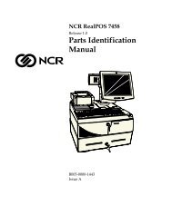
Serial Number/Model Number Label<br />
The unit’s serial number, model number, tracer number, and date of<br />
manufacture are included on a label on the back of the Core Module.<br />
Toviewthelabel,tilttheCoreModuleandremovethecablecover.<br />
Note: The serial number is repeated on the non-MSR side of the Core<br />
Module.<br />
Class/Model<br />
NCR<br />
0<br />
<strong>7455</strong>-2002-M016<br />
50-34697073<br />
50-000038<br />
Mfg Date : 03/16/01<br />
Serial Number<br />
Tracer Number<br />
Date Manufactured<br />
18372
Chapter 1: Product Overview 1-3<br />
Hardware Modules<br />
Base Unit<br />
• ProcessorBoard&POSConnectorBoard<br />
−<br />
−<br />
−<br />
−<br />
−<br />
−<br />
−<br />
−<br />
−<br />
−<br />
−<br />
−<br />
−<br />
−<br />
−<br />
−<br />
−<br />
−<br />
DynaKey User Interface<br />
600 MHz Intel Celeron ® Processor<br />
32 MB On-board Memory<br />
SODIMM Memory Socket with support up to 256 MB RAM<br />
4 MB Video Memory with SVGA Chipset<br />
1 MB Flash ROM BIOS (not CMOS)<br />
Four (4) 9-pin RS-232 Ports (two powered)<br />
Two (2) USB Ports<br />
PS/2 Keyboard Port<br />
PS/2 Mouse Port provides support for mouse via adapter cable<br />
Powered Parallel Port (adapter cable available to convert to<br />
standard parallel port)<br />
Cash Drawer Port<br />
Wedge Scanner Port<br />
10/100 Ethernet LAN Chipset, Wake-on-LAN support, and RJ-<br />
45 port<br />
PCAudioOutputwithanInternalMonoSpeaker<br />
Sound Blaster ® 16 Compatible Audio Chipset<br />
External VGA Display Port (This does not allow different<br />
information on each display. If you use an external display, you<br />
get the same screen that you do on the operator display.)<br />
IDE support for a Hard Disk and an Optional Flash Disk
1-4 Chapter 1: Product Overview<br />
Hardware Options<br />
• 12.1" Operator Display – Passive (DSTN) or Active (TFT) Matrix<br />
Display<br />
• Integrated Motion Sensor, capable of waking up the terminal from<br />
a low power state<br />
• Integrated Power Supply with Table Top Mount<br />
• Integrated Keylock<br />
• Power on/Status LED Indicator Light<br />
• <strong>Re</strong>set switch which can be used to recover from a lock-up condition<br />
• 2.5" High Capacity Hard Disk<br />
• 3 Track MSR (ISO or JIS)<br />
• Integrated Bootable CD ROM<br />
• 5-wire <strong>Re</strong>sistive Touch Screen<br />
• PCMCIA Card Slots (for modem or wireless LAN)<br />
• Customer Displays<br />
−<br />
−<br />
−<br />
−<br />
No Customer Display<br />
4x20 Display (Telescoping or Integrated)<br />
2x20 Display (<strong>Re</strong>mote Post or Table Top)<br />
International VFD (Asian Character Support, <strong>Re</strong>mote)<br />
• Flash Disk (32 MB)<br />
• Mouse Adapter Cable<br />
• Parallel Port Adapter Cable<br />
• Ethernet Cable (3 meter)
Chapter 1: Product Overview 1-5<br />
• Cash Drawers<br />
− Compact Cash Drawer (2113)<br />
− Full-Size Cash Drawer (2189)<br />
− Mid-Range Cash Drawer (7454-K005)<br />
− Up to two drawers supported via Y cable<br />
• Printers:<br />
− 7158 Thermal <strong>Re</strong>ceipt Printer w/Slip (MICR and Check Flip)<br />
− 7162 Impact R/J Printer w/Slip<br />
− 7166 Thermal <strong>Re</strong>ceipt Printer w/Slip (Asian Character Support)<br />
− 7194 Thermal <strong>Re</strong>ceipt Printer<br />
− 7196 Thermal <strong>Re</strong>ceipt Printer (Asian Character Support)<br />
− <strong>Re</strong>mote Printer Cables<br />
• PC Keyboard<br />
• USB RS-232 Port Server<br />
− USB Serial Converter – 4 Port (2338-K008)<br />
− USB Serial Converter – 2 Port (2336-K012)<br />
• Scanners:<br />
− 7837 Hand Held Scanner<br />
− 7870 Scanner/Scale<br />
− 7872 Scanner/Scale<br />
− 7875 Bi-Optic Scanner<br />
− 7880 Scanner/Scale<br />
− 7892 Bi-Modal Presentation Scanner
1-6 Chapter 1: Product Overview<br />
• Electronic Payment Devices:<br />
− 5992 Signature Capture Device<br />
− 5945 Electronic Payment Device<br />
• Power Cords:<br />
− US Power Cord<br />
− US Twist Lock Power Cord<br />
− International Power Cord<br />
− Australian Power Cord<br />
− UK Power Cord<br />
− SEV Power Cord<br />
− Japan Twist Lock Power Cord
Chapter 1: Product Overview 1-7<br />
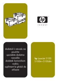
System Configuration Diagram<br />
NOTE: 7837 connect<br />
to RS-232 or Wedge<br />
7837<br />
5972-2000<br />
Customer<br />
Display<br />
Serial Only<br />
5972-1000<br />
Customer<br />
Display<br />
7448<br />
Customer<br />
Display<br />
PS/2 or USB<br />
Keyboard<br />
5973<br />
International<br />
Customer<br />
Display<br />
*<br />
NOTE: 7158 & 7196 connect<br />
to RS-232 or USB<br />
* *<br />
RS-232 Transaction Printers<br />
PS/2 LCD<br />
KBD<br />
Aux<br />
Power<br />
USB<br />
Wedge<br />
7 8 9<br />
4 5 6<br />
1 2 3<br />
0<br />
CRT<br />
Operator or<br />
Customer<br />
Display<br />
VGA Parallel/<br />
Serial<br />
Aux Power<br />
Parallel<br />
7196 7194 7166 7158<br />
7162<br />
2189 7454-K005 2113<br />
<strong>7455</strong><br />
Cash Drawer<br />
Aux Power<br />
LAN<br />
Cash Drawers<br />
RS-232 Peripherals<br />
Ethernet<br />
AC<br />
Only<br />
AC<br />
Only<br />
AC<br />
7875<br />
Scanner/Scale<br />
7872<br />
Scanner/Scale<br />
7880<br />
Scanner/Scale<br />
7892<br />
Bi-modal<br />
Presentation<br />
Scanner<br />
5945<br />
Electronic<br />
Payment<br />
Terminal<br />
5992<br />
Signature<br />
Capture<br />
18984
1-8 Chapter 1: Product Overview<br />
Hardware Module Descriptions<br />
Processor Board<br />
Processor/Chip Set<br />
The terminal uses a Celeron processor (µPGA2 package), used with the<br />
Intel 440BX PC chipset. The 440BX chipset consists of the 82443BX<br />
System Controller and the 82371EB PCI ISA Accelerator, also called the<br />
PIIX4E.Thischipsetincludes100MHzsystembusandmemory<br />
support, 64 bit bus width, and AGP video interface.<br />
Video Subsystem<br />
The video subsystem supports the following LCD types:<br />
• 12.1" passive matrix (DSTN) 800x600 with 32 K effective colors<br />
• 12.1" active matrix (TFT) 800x600 with 64 K colors<br />
Support for the LCD integrated display is provided internally. External<br />
support for SVGA monitors (800x600 [or better] resolution and 64 K [or<br />
better] colors) is provided by a CRT 15-pin D-shell connector.<br />
The LCD brightness is software controlled. Neither terminal has<br />
hardware controls for brightness or contrast.<br />
The LCD back lighting is also software controlled. In addition to OFF<br />
and ON modes, a dimmed mode is supported in the hardware to allow<br />
i<strong>ncr</strong>eased tube life and less power consumption. If appropriate<br />
software drivers are loaded, full brightness is restored when a key is<br />
pressed or the screen touched (on touch screen models), motion<br />
detection (Motion Sensor section), or an application request (i.e., to play<br />
promotional material on a preset schedule).
Chapter 1: Product Overview 1-9<br />
Ethernet 10/100Base-T LAN Communications<br />
The terminal contains a 10/100Base-T Ethernet PCI connection.<br />
Ethernet 100Base-T is also known as “Fast Ethernet.” The Boot ROM<br />
for diskless boot functionality is included in the 1 MB system ROM.<br />
The hardware is compatible with the TCP/IP, DHCP, and TFTP<br />
protocols required for remote boot of the platform. Appropriate<br />
software must be used to enable each protocol used over the Ethernet<br />
link.<br />
The terminal may be connected to either a 10 MB/s or 100 MB/s<br />
Ethernet connection. The hardware automatically selects the correct<br />
speed (if enabled by software to do so).<br />
The LAN hardware supports wakeup packet capability as defined in<br />
the Device Class Power Management Specification, Network Device<br />
Class (available from the Microsoft ® Web site).<br />
When the platform is in the Soft OFF state, receipt of a Wakeup Packet<br />
on the LAN can return the system to the ON state, if this feature is<br />
enabled by software.<br />
Note: Due to limitations of the LAN controller and the OS, all features<br />
described in the Network Device Class specification may not be<br />
available.<br />
100Base-T is wired identically to 10Base-T, except that the twisted pair<br />
cable must be Category 5 and the hubs must permit 100 or 10/100<br />
MB/s operation. Although 10Base-T will operate on Category 3 twisted<br />
pair, or NCR “747” cable, an upgrade to Category 5 is required for<br />
100Base-T.<br />
A customer desiring to use the terminal in an existing 10Base-T<br />
environment can do so and simply run at 10 MB. In order to upgrade to<br />
100 MB/s, Category 5 cable and 100 or 10/100 hubs must be installed.<br />
NCR strongly recommends the use of Category 5 for all new cabling,<br />
even if the customer initially intends to run only 10Base-T.<br />
LED Indicators for Link Integrity (verifies cable and hub connection are<br />
good) and LAN speed is provided on the Processor Board near the row<br />
of connectors at the bottom of the e-box. The LED is ON (yellow) when<br />
the speed is running at 100 MB/s.
1-10 Chapter 1: Product Overview<br />
Link Integrity is provided to the PC chipset to permit boot-up software<br />
to verify the presence of the LAN connection. Software must allow 2<br />
seconds after power-up for the Link Integrity signal to become valid.<br />
Wireless LAN Communications<br />
Where a wired Ethernet connection is not desired, a wireless LAN<br />
adapter may be installed in the PCMCIA socket. This requires that the<br />
PCMCIA daughterboard feature be installed. A wireless LAN used in<br />
the terminal must meet the following requirements:<br />
• Integrated antenna that meets the requirements of PCMCIA (PC<br />
Card) Extended Type 2 card definition (a maximum of 5-cm<br />
additional length).<br />
• Power consumption within the capabilities of the PCMCIA<br />
daughterboard.<br />
• Signaling requirements within the capabilities of the terminal<br />
PCMCIA interface. The main restriction is that DMA transactions<br />
are not supported over the PCMCIA interface.<br />
• Device drivers for the targeted operating system must exist.<br />
• Appropriate infrastructure (server support, Base Stations, Ceiling<br />
Antennas, etc) must be present in the installation site, and the<br />
maximum RF range of the wireless system must not be exceeded.<br />
Interoperability – While the 802.11 standard provides an interoperable<br />
protocol definition, there are vendor-specific extensions to the protocol<br />
that encourage users to stay with one supplier’s equipment. This also<br />
applies to wireless infrastructure and access points; 802.11 does not<br />
govern this operation. Mixing of RF suppliers on a site is not<br />
recommended until the RF suppliers have demonstrated<br />
interoperability.<br />
Note: It is possible that other LAN PC cards may work; however,<br />
NCR does not certify all configurations.<br />
<strong>Re</strong>mote Wakeup over the wireless network is not possible because the<br />
cards do not support it. An alternative is to use the system real-time<br />
clock wake-up at a scheduled time.
Chapter 1: Product Overview 1-11<br />
Depending on the OS environment, <strong>Re</strong>mote Boot may be supported,<br />
but due to the slow network speed a large boot image may take an<br />
unacceptably long time to load. The application developer needs to<br />
ensure that the load is of reasonable size.<br />
The wired Ethernet connection is not certified for use in configurations<br />
where a wireless adapter is installed.<br />
Universal Serial Bus<br />
Three USB Type-A ports are provided on the terminal, one of which is<br />
reserved for integrated devices and not externally accessible. Only two<br />
of the USB ports can be active at the same time. If the auxiliary USB<br />
port,locatedneartheMSR,isenabled,oneofthetwoportsonthe<br />
main connector row becomes disabled. This is controlled from the<br />
BIOS setup menu. USB Host Controller support is provided on the<br />
Processor Board.<br />
Note: USB peripherals require support from the operating system,<br />
which is currently limited to Windows ® 98, Windows 2000, and<br />
Windows NT ® SP 5.<br />
Serial Ports<br />
The terminal supports up to four RS-232 ports. Four 9-pin D-shell<br />
connectors are provided. RS-232/A & C are powered ports to supply<br />
power through the serial connection on a peripheral. RS-232/B & D are<br />
not powered and available for other serial peripherals such as a<br />
printer.<br />
RS-232 Connector Pinout (DB-9 connector, male)<br />
Pin Connector 1 Connector 2 Pin Connector 1 Connector 2<br />
1 DCD DCD 6 DSR DSR<br />
2 RXD RXD 7 RTS RTS<br />
3 TXD TXD 8 CTS CTS<br />
4 DTR DTR 9 RI or +12 VDC RI<br />
5 GND GND
1-12 Chapter 1: Product Overview<br />
Hardware Monitor<br />
The hardware monitor generates an interrupt to the system whenever<br />
any of the internal voltages used by the system processor goes above or<br />
below the acceptable operating range. An interrupt is also generated<br />
when the temperature of the Processor exceeds safe levels. Software<br />
can use this indication to slow or stop the system and/or force a reset.<br />
PCI Expansion Header<br />
A single expansion header is provided to support optional features,<br />
such as the PCMCIA for Wireless LAN Board. This board supports two<br />
Type 2 or one Type 3 PCMCIA-type cards.<br />
IDE Header<br />
Two IDE headers are provided to support the 2.5" hard disk drive and<br />
the optional integrated CD-ROM.<br />
Audio<br />
The base unit has Sound Blaster-compatible audio. Wave table<br />
synthesis is not supported. FM synthesis and MIDI are supported in<br />
the hardware, but require software driver support to function.<br />
A Line Out is provided on a 3.5mm stereo jack that permits connection<br />
of external amplified speakers.<br />
The amplifier connected to Line Out must be used in order to play<br />
Sound Blaster (audio subsystem) audio. However, an internal EUI<br />
speaker provides PC speaker functionality (beeps and tones) for all<br />
configurations.<br />
The volume control can be set during system configuration.
Chapter 1: Product Overview 1-13<br />
Magnetic Stripe <strong>Re</strong>ader<br />
A 3-track MSR head is available as an option. The ISO and JIS card<br />
formats are supported.<br />
When card data is read, an interrupt is generated. A software device<br />
driver for the MSR must be loaded to allow the application to process<br />
the data.<br />
Optional Touch Screen Controller<br />
On NCR <strong>7455</strong> <strong>Re</strong>tail Terminals that contain the optional touch screen,<br />
the MicroTouch ® “Excalibur” chip is used to interface the touch panel.<br />
This controller supports the MicroTouch 5 wire resistive panel.<br />
In order to save an RS-232 port, the touch data is delivered to the<br />
system through the PS/2 interface. This requires a mouse-aware touch<br />
device driver for the appropriate OS.<br />
Note: The <strong>7455</strong> does not support PS/2 mouse devices on units that<br />
have the optional touch screen because the touch screen uses the PS/2<br />
port.
1-14 Chapter 1: Product Overview<br />
When the system is operating in the dimmed display mode, touch<br />
activity can restore full brightness if instructed by software to do so.<br />
When the system is in low power mode, touch activity can generate the<br />
mouse port interrupt (IRQ12).<br />
Processor Board Connectors<br />
Caution: The Ethernet port and the scanner port are identical in size.<br />
Be certain the scanner and the Ethernet cables are plugged into the<br />
correct ports. Permanent damage to an Ethernet hub will result if it is<br />
plugged into the scanner port.<br />
Note: 12VDC output on the powered RS-232 ports.<br />
VGA LAN USB RS-232/A RS-232/B<br />
Powered<br />
Mouse<br />
Power<br />
Infared Speaker<br />
Speaker Out<br />
RS-232/D<br />
RS-232/C<br />
Powered<br />
Keyboard<br />
Scanner Mic Parallel<br />
(Customer Display)<br />
Cash<br />
Drawer<br />
18367
Chapter 1: Product Overview 1-15<br />
External Motherboard Connectors<br />
• VGA CRT RGB 15-pin D-Shell<br />
• Ethernet RJ45 (See warning below)<br />
• Dual USB Type A<br />
• RS-232 9-pin D-Shell (two, one with +12V power option)<br />
• PS/2 Connector—also supports mouse via mouse interface cable<br />
• RS-232 9-pin D-Shell (two, one with +12V power option)<br />
• Power Supply<br />
• IRDA Transceiver Interface<br />
• PS/2 Port<br />
• Speaker Port<br />
• Speaker Out (amplified) 3.5mm Jack<br />
POS Daughterboard Connectors<br />
• Cash Drawer (supports 2 drawers on one connector)<br />
• VFD Connector (parallel port plus power)<br />
• Microphone Connector<br />
• Wedge Scanner Port (see caution below)<br />
• PS/2 Port (keyboard)<br />
• RS-232/C (powered)<br />
• RS-232/D<br />
Optional Connectors: <strong>Re</strong>quires PCMCIA Adapter Daughterboard<br />
• PCMCIA Type 2 (2 slots)
1-16 Chapter 1: Product Overview<br />
Internal Motherboard Connectors<br />
• LCD<br />
• Backlight Inverter<br />
• MSR<br />
• Touch Screen<br />
• Motion Sensor/Power Indicator<br />
• PCI Expansion Header<br />
• Primary IDE (hard drive)<br />
• Secondary IDE (CD-ROM)<br />
• POS Connector Board Header<br />
• USB Port 3<br />
• Fan<br />
• DynaKey Connector (2)<br />
• Internal Speaker<br />
Caution: The wedge scanner port on the POS daughter-card and the<br />
Ethernet port on the processor board are the same type of connector.<br />
The Ethernet cable and port are labeled with the PC99 standard<br />
connector color (black) for Ethernet devices to reduce the risk of<br />
plugging these devices incorrectly. If an Ethernet hub is connected to<br />
the powered scanner port, the Ethernet hub will be permanently<br />
damaged.<br />
Note: The scanner port comes with a blank connector plug installed.<br />
This plug must be removed before a device can be connected to the<br />
scanner port.
Chapter 1: Product Overview 1-17<br />
Flash Disk<br />
An optional 32 MB Flash Disk provides non-volatile storage that is<br />
additional to and separate from the hard disk, allowing storage for<br />
items traditionally placed in retail CMOS (e.g., hard totals). OPOS<br />
drivers are available to support the Flash Disk.<br />
Flash Disk Interface<br />
The board provides support for a Flash Disk array in the form of an M-<br />
Systems DiskOnChip ® . A 32-pin socket is provided for this feature. The<br />
Flash Disk must be installed and enabled in BIOS Setup.<br />
Power LED<br />
The Processor Board provides support for an external power LED<br />
through the on-board Motion/Power LED connector. This LED is<br />
controlled through the SMC 37C935 GPIO pins. Once the SMC chip is<br />
programmed to support the Power LED function on GPIO pin 13, the<br />
LED is turned “on” anytime all power to the Processor Board is good.<br />
The system’s power management software has the option to turn the<br />
LED “off” indicating the system is in a power-managed mode.<br />
MSR<br />
The MSR interface supports a maximum of 3 tracks of magnetic stripe<br />
information for support of ISO and JIS format cards. Activate the MSR<br />
interface by enabling it in BIOS Setup, under IO Configuration. The<br />
MSR interface controller is a memory-mapped device, which can reside<br />
at system memory address CA000, CC000, or D0000. If MSR capability<br />
is not desired, it may be disabled through BIOS Setup.<br />
Graphics Subsystem<br />
The <strong>7455</strong> <strong>Re</strong>tail Terminal is equipped with an SMI Lynx SVGA<br />
LCD/CRT 3DM graphics controller with 8 MB of integrated<br />
synchronous graphics DRAM.<br />
The Processor Boards support linear addressing by creating a “hole” in<br />
the memory address space at the 63 MB boundary. When the system is<br />
configured for 64 MB and linear addressing is enabled, the last 1 MB of<br />
system memory is unusable; therefore, the board will report that total<br />
available system memory is 63 MB.
1-18 Chapter 1: Product Overview<br />
Because a hole in memory creates a non-contiguous address space,<br />
enabling linear addressing when total system DRAM is greater than<br />
64 MB is not recommended. Video linear addressing is enabled<br />
through PC Setup under the Integrated Peripherals menu.<br />
The processor also supports VESA standards such as the VESA DPMS<br />
protocol to place a DPMS compliant monitor into power savings<br />
modes.<br />
<strong>Re</strong>solutions Supported<br />
<strong>Re</strong>solution Colors Max Vfreq<br />
800x600x8bpp 256 85 Hz<br />
800x600x16bpp 64 K 85 Hz<br />
800x600x24bpp 16 M 85 Hz<br />
Colors Supported<br />
<strong>Re</strong>solution<br />
256 Colors<br />
(8-Bit)<br />
65,000 Colors<br />
(16-Bit)<br />
16.7 M Colors<br />
(24-Bit)<br />
800x600 512 K 1 MB 2 MB<br />
Board BIOS<br />
The Processor Board uses a Phoenix BIOS, which is stored in Flash<br />
ROM and easily upgraded through the network connection or serial<br />
port. The Flash EEPROM also contains the Setup utility, Power-On Self<br />
Tests (POST), and APM 1.2. The board also supports system BIOS<br />
shadowing, allowing the BIOS to execute from on-board writeprotected<br />
DRAM.<br />
The BIOS displays a sign-on message during POST, identifying the<br />
type of BIOS and a five-digit revision code.
Chapter 1: Product Overview 1-19<br />
Flash Memory Implementation<br />
The Intel E28F800B5-T70 Flash component is organized on board as<br />
1024 K x 8 (1 MB). While a typical PC BIOS image including video and<br />
LAN boot ROM code normally fits in 512 K, the board supports a<br />
1 MB Flash ROM. The Flash device contains the PC System BIOS along<br />
with the Video BIOS and LAN boot ROM which compresses the ROM<br />
images into a single binary image.<br />
The Flash device is divided into four areas, as described below.<br />
System Address Flash Memory Area<br />
F0000H FFFFFH 64 K Main BIOS<br />
EE000H EFFFFH 8 K System BIOS <strong>Re</strong>served during boot<br />
ED000H EDFFFH 4 K Plug and Play ESCD Storage Area<br />
E0000H ECFFFH 52 K System/VGA BIOS <strong>Re</strong>served during boot<br />
BIOS Upgrades<br />
Flash memory makes distributing BIOS upgrades easy. Anewversion<br />
of the BIOS can be installed from the hard disk, network, integrated<br />
CD-ROMorthroughanexternalCD-ROM.<br />
The disk-based Flash upgrade utility, PHLASH.EXE, ensures the<br />
upgrade BIOS extension matches the target system to prevent<br />
accidentally installing a BIOS for a different type of system.<br />
Setup Utility<br />
The ROM-based Setup utility allows the system configuration to be<br />
modified without opening the system for most basic changes. The<br />
Setup utility is accessible only during the Power-On Self Test (POST)<br />
by pressing the key after the POST memory test has begun and<br />
before boot begins. A prompt may be enabled that informs users to<br />
press the key to access Setup.<br />
Note: An external alphanumeric keyboard is required to run the BIOS<br />
CMOS Setup Utility on units not equipped with a touch screen.
1-20 Chapter 1: Product Overview<br />
Plug and Play<br />
The Processor BIOS also has a setup option to support the Windows<br />
runtime plug and play utilities. When this option is selected, only<br />
devices critical to boot are assigned resources by the BIOS. Device node<br />
information is available for all devices to ensure compatibility with<br />
Windows 95. System configuration information is stored in ESCD<br />
format. The ESCD data is cleared upon loss of the CMOS voltage.<br />
Advanced Power Management<br />
The Processor BIOS has support for both 1.1 and 1.2 Advanced Power<br />
Management (APM). The version of APM drivers loaded in the<br />
operating system by the user determines to which specification the<br />
BIOS will adhere. In either case, the energy saving Standby mode can<br />
be initiated by a keyboard hot key sequence or a time-out period set by<br />
the user.<br />
When in Standby mode, the Processor Board reduces power<br />
consumption by using the processor System Management Mode<br />
(SMM) capabilities and by spinning down hard drives and turning off<br />
VESA DPMS compliant monitors. During setup, the user may select<br />
which DPMS mode (Standby, Suspend, or Off) is sent to the monitor.<br />
The ability to respond to external interrupts is fully maintained while<br />
in Standby mode allowing the system to service requests such as incoming<br />
data or network messages while unattended. The user may<br />
also select any keyboard or mouse activity to take the system out of the<br />
energy saving Standby mode. When this occurs, the monitor and IDE<br />
drives are turned back on immediately.<br />
APM is disabled in BIOS by default; therefore, the user must enable<br />
this feature. The system must be configured with an APM driver in<br />
order for the system power saving features to take effect.
7 8 9<br />
4 5 6<br />
1 2 3<br />
Chapter 1: Product Overview 1-21<br />
Operator Display<br />
0<br />
18427<br />
The <strong>7455</strong> is available with either a 12.1" TFT (active matrix) or a 12.1"<br />
DSTN (passive matrix) LCD.<br />
DSTN LCD panels require a contrast adjustment for optimal viewing.<br />
Contrast control is set by software, using a digital potentiometer on the<br />
Processor Board. The terminal does not have a user-accessible contrast<br />
adjustment. Software can set a default value after reading the Panel ID.<br />
Display contrast changes with temperature. The DSTN panels contain<br />
temperature-compensation circuitry that adjusts contrast automatically<br />
as the temperature of the panel changes.<br />
LCD Adapter Cable<br />
The signals from the LCD header on the main board are brought up to<br />
the LCD on a flex adapter cable. This cable plugs directly into the LCD<br />
panel from the motherboard. The type of cable used is specific to the<br />
type of LCD used. Each LCD has a specific panel I.D. which is<br />
identified to the hardware system through the adapter cable.
1-22 Chapter 1: Product Overview<br />
LCD Backlight Inverter Module<br />
The Inverter Board supplies power for the LCD backlight. The Inverter<br />
has a connector that receives power, ground, and a backlight dimming<br />
signal from the processor board. The Inverter generates the high<br />
voltage necessary to start and run a CCFL backlight.<br />
Brightness of the LCD backlight is controlled by altering the current<br />
delivered to the LCD tubes. When instructed by software, a digital<br />
potentiometer on the Processor Board is used to adjust the backlight<br />
dimming signal, which the Backlight Inverter Board then uses to set<br />
the current level to the tubes.<br />
Power to the Inverter is protected by a fuse located on the Inverter<br />
Board. This fuse protects the system from damage in the event of a<br />
backlight or Inverter Board fault. If one or both backlight tubes become<br />
disconnected or otherwise open-circuited, protection circuitry shuts<br />
down the Inverter.<br />
On the TFT (Active Matrix) models, the LCD has only one backlight<br />
and operates at a different current that the DSTN (Passive Matrix).<br />
Therefore, the Inverter power harness contains a current-limiting<br />
resistor to provide the correct current to the backlight.<br />
DynaKey<br />
The DynaKey operator input device is integrated in the <strong>7455</strong> <strong>Re</strong>tail<br />
Terminal and is the main source of input from the operator. The<br />
DynaKey interface offers a standard 10-key setup surrounded by<br />
programmable buttons for any variety of functions. The DynaKey is<br />
connected to the POS daughterboard via two ribbon cables.<br />
Touch Screen (Optional)<br />
The optional resistive Touch Screen completely covers the LCD and is<br />
mounted directly in front of the LCD, behind the front plastic bezel of<br />
the terminal. The touch controller on the Processor Board supports<br />
resistive touch glass.
Chapter 1: Product Overview 1-23<br />
NCR <strong>7455</strong> <strong>Re</strong>mote Displays<br />
The touch glass has an integrated harness that is routed into the<br />
Processor Board enclosure and is connected to a header on the<br />
Processor Board. The touch glass has a glare-reducing texture that also<br />
helps hide fingerprints.<br />
The touch screen cannot be used with a PS/2 mouse connected to the<br />
<strong>7455</strong>. As an alternative, a serial mouse can be used.<br />
The <strong>7455</strong> <strong>Re</strong>tail Terminal supports these remote customer displays:<br />
4x20 VFD Customer Display<br />
The 4x20 VFD Display in two variations:<br />
• Integrated<br />
• Integrated with a High Post<br />
The 4x20 VFD supports four lines of twenty characters.<br />
NCR 5972 2x20 VFD Customer Display<br />
The NCR 5972 2x20 VFD Display in two variations:<br />
• Table-Top Mount<br />
• High-Post Mount<br />
The NCR 5972 2x20 VFD supports two lines of twenty characters.<br />
NCR 5973 International VFD Customer Display<br />
The NCR 5973 VFD (Vacuum Fluorescent Display) is an optional<br />
display device for the <strong>7455</strong> <strong>Re</strong>tail Terminal. The VFD is available in<br />
models that have a combination of:<br />
• Mounting configurations<br />
• System-specific cables
1-24 Chapter 1: Product Overview<br />
Table Top Mount<br />
12271<br />
16" High Post Mount<br />
17198
7 8 9<br />
4 5 6<br />
1 2 3<br />
Chapter 1: Product Overview 1-25<br />
Features<br />
Magnetic Stripe <strong>Re</strong>ader<br />
A single, 3-track, analog Magnetic Stripe <strong>Re</strong>ader (MSR) is available as a<br />
feature, supporting ISO and JIS format cards. When the MSR is not<br />
desired, a filler piece for the MSR section is included to make the unit<br />
appear uniform.<br />
MSR<br />
0<br />
18362
1-26 Chapter 1: Product Overview<br />
Printer Options<br />
Each printer receives its power from an external power supply, has a<br />
serial interface, and has a connector for cash drawers. The sections that<br />
follow provide an illustration and brief description of each printer.<br />
Note: The <strong>7455</strong> power supply does not provide a 24V line for printers.<br />
Therefore, any printer connected to the <strong>7455</strong> requires a separate power<br />
supply.<br />
7162 Printer<br />
The 7162 is a dot matrix printer that provides up to 40 columns of<br />
receipt and journal print, and up to 88 columns of slip print. The<br />
printer’s features include paper low sensors, slip-out detectors,<br />
automatic paper cutting, and two cash drawer kick-out connectors.
Chapter 1: Product Overview 1-27<br />
7158 Printer<br />
The 7158 Printer is an extremely fast, quiet, and reliable point-of-sale<br />
device. It consists of two specialized printers in one compact package:<br />
a thermal printer on top that prints receipts, and an impact slip printer<br />
in front to print on forms and checks that you insert. The printer can be<br />
connected through a USB or serial port.<br />
17304<br />
7166 Printer<br />
The 7166 Printer is an extremely fast, quiet, and reliable point-of-sale<br />
printer. It consists of two specialized printers in one compact package:<br />
a thermal printer that prints receipts, and an impact slip printer.<br />
17303
1-28 Chapter 1: Product Overview<br />
7194 Printer<br />
The 7194 Printer is a high speed, high-resolution printer, capable of<br />
both text and graphics printing. It offers direct thermal printing in a<br />
receipt station. The 7194 can connect through a USB port or a serial<br />
port.<br />
16437<br />
7196 Printer<br />
The 7196 Printer is a high speed, high-resolution printer, capable of<br />
both text and graphics printing.<br />
17302
Chapter 1: Product Overview 1-29<br />
Other Integrated Devices and Indicators<br />
Hard Disk Drive<br />
A 2.5" IDE Hard Disk is included. The drive is the standard type that is<br />
usedbynotebookPCs.Theharddrivecanbeupgradedorreplaced<br />
through a special service access panel on the back of the unit. The hard<br />
drive interfaces through the primary IDE connection on the processor<br />
board.<br />
<strong>Re</strong>set Switch<br />
The <strong>Re</strong>set Switch is provided as a last resort to reboot the system if the<br />
software reset port mechanisms fail. This switch is located on the row<br />
of connectors that are located at the bottom of the enclosure. Although<br />
not intended to be easily accessible, the reset switch can be operated<br />
without removing covers or using any special tools.<br />
Note: On early models, there may be a hole in the cabinet providing<br />
access to the <strong>Re</strong>set Switch.<br />
<strong>Re</strong>set Switch<br />
18373<br />
<strong>Re</strong>set Procedure<br />
1. Press the <strong>Re</strong>set Switch and hold it in for more than 4 seconds. The<br />
screen goes blank.<br />
2. Press the <strong>Re</strong>set Switch again. The system then reboots.
1-30 Chapter 1: Product Overview<br />
Internal Speaker<br />
The Internal Speaker is connected to the PC speaker output of the<br />
system chipset, not to the audio subsystem. It is connected to the<br />
Processor Board via a harness, and is mounted inside the Processor<br />
Board enclosure.<br />
Motion Sensor<br />
The terminal hardware can detect movement near the terminal and<br />
enables software to prompt system operation from a low-power state.<br />
Application software may also be able to make use of motion detection<br />
when in the ON state if it is enabled by lower-level software.<br />
7 8 9<br />
4 5 6<br />
1 2 3<br />
Motion<br />
Sensor<br />
PowerStatus LED<br />
18363<br />
Motion is detected as a change in ambient light level that is greater<br />
than a software-controlled threshold.
Chapter 1: Product Overview 1-31<br />
A photodiode mounted behind the front bezel of the unit senses<br />
ambient light levels. The photodiode resides on a small circuit board<br />
(the Motion Sensor Board). A harness connects the Motion Sensor<br />
Board to the amplifier and motion sensing logic on the Processor<br />
Board. The user Power/Status LED indicator shares this board.<br />
Power/Status LED<br />
The LED power indicator indicates that power is present. The LED is<br />
green when the processor and BIOS are operating properly. The LED is<br />
mounted behind the front bezel on the same board as the motion<br />
sensor.<br />
LAN Status LEDs<br />
LAN Integrity<br />
(green)<br />
LAN Speed<br />
Yellow = 100 MB<br />
18364
1-32 Chapter 1: Product Overview<br />
Power Supply<br />
The terminal uses an AC adapter for its power supply, concealed in the<br />
terminal mounting. The supply is inaccessible when the terminal is in<br />
the normal operation and mounting position to prevent tampering,<br />
and is sealed to help protect against spills or other environmental<br />
hazards.<br />
Note: The power supply automatically senses the proper AC voltage;<br />
therefore, only normal servicing access is required.<br />
• All power required to operate the base unit, PCMCIA option and<br />
PCMCIA cards, speaker option, scanner option, and bus-powered<br />
USB peripherals is provided by the power supply.<br />
• The Processor Board serves as the hub to distribute power to all<br />
terminal functions. Cash drawers, VFD customer display, PS/2<br />
keyboard, PCMCIA daughter board and slots, scanner (through<br />
RS-232 port), USB, hard disk, and LCD all receive power through<br />
their respective Processor Board connectors.<br />
• Printers requiring 24V are not supported by the <strong>7455</strong> power supply<br />
but can be used if they are powered with an external power supply.<br />
Note: The power available to peripherals depends on the<br />
configuration of the base terminal and the power required by the<br />
peripherals. Careful consideration of the power demands of the system<br />
should be taken to ensure it does not exceed that provided by the <strong>7455</strong><br />
power supply.
Chapter 1: Product Overview 1-33<br />
The following table notes the power requirements of the most common<br />
peripherals.<br />
Item Description 3.3VDC 5.0VDC 12VDC <strong>Re</strong>quires Ext.<br />
Power Source<br />
Power Supply (95 Watts 497-0415258) 4.10 9.30 2.90<br />
Summa POS Motherboard with CPU, &<br />
up to 256MB RAM<br />
2.00 3.00 0.04<br />
Personality Board 0.20<br />
Power available for Peripherals 2.10 6.10 2.86<br />
LCDs: Samsung TFT 006-8603280, or<br />
Sharp DSTN 006-8601845<br />
0.29 0.80<br />
MSR Modules 0.00 0.00 0.00<br />
Touch Screen feature 0.25<br />
<strong>Re</strong>mote speakers 0.33<br />
Cash Drawer<br />
(no more then one simultaneous opening)<br />
0.00 0.00 0.00<br />
Printers (always require brick) 0.00 0.00 0.00 X<br />
2337-K002 Sampo 12.1" color LCD - analog<br />
interface(497-0415562)<br />
7452-K419 COMPAL 15" Color CRT (497-0414127) X<br />
X<br />
External CD-ROM Drive<br />
(Parallel, 2336-K007, 497-0411213)<br />
0.00 0.00 0.00 X<br />
7880 Scanner/Scale X<br />
7872 Scanner/Scale X<br />
7875 Bi-Optic Scanner X<br />
7452-K891 CCD Hand Held Scanner (008-0221512) X<br />
Safety - Contingency 0.20 0.50 0.30
1-34 Chapter 1: Product Overview<br />
Item Description 3.3VDC 5.0VDC 12VDC <strong>Re</strong>quires Ext.<br />
Power Source<br />
Power available for Peripherals 1.61 5.35 1.43<br />
Hard Disk Drive 2.5" 0.50<br />
CD-ROM(TEAC, 24X) 006-8603220 C 1.00<br />
Keyboards 0.20<br />
Display 4x20 VFD Powered from Parallel Port 1.00<br />
Display 4x20 VFD Powered from Serial Port 0.45<br />
Display 4x20 VFD Int’l, Powered from Parallel Port<br />
(008-0221541)<br />
2.00<br />
Display 2x20 VFD Powered from Serial Port 0.50<br />
USB to 4 port RS-232 (2336-K008, 497-0413014) 0.50<br />
USB to 2 port RS-232 (2336-K012, 497-0413710) 0.50<br />
PCMCIA Controller 0.40<br />
IRDA 0.50<br />
5992 Signature Capture Device (497-0417590) 0.80<br />
5945 Electronic Payment Device (497-0411818) 0.50<br />
7837 Hand Held Scanner 0.30<br />
7892 Presentation Scanner 0.50<br />
7882 Scanner 0.60
Chapter 1: Product Overview 1-35<br />
USB RS-232 Port Server<br />
The USB RS-232 Port Server is an intelligent, stackable expansion<br />
module that connects to the terminal USB port, providing high-speed<br />
RS-232 serial ports.<br />
USB Port<br />
RS-232 Ports<br />
16944
1-36 Chapter 1: Product Overview
Chapter 2: Hardware Installation<br />
Introduction<br />
Installation Summary<br />
The terminal is fully assembled at the factory. This chapter explains the<br />
mounting options and how to connect optional hardware components<br />
to the terminal.<br />
The terminal should be removed from the shipping packaging and<br />
visual checks made to verify the correct hardware configuration. The<br />
system is then configured and any communication cables are<br />
connected.<br />
Only after inspection should the power cord be attached to the system<br />
and then connected to the AC power source. Power-up self-tests are<br />
run to verify basic functionality.<br />
ROM-based setup should be used to configure network options. Full<br />
configuration depends on the system server and the management Web<br />
site.
2-2 Chapter 2: Hardware Installation<br />
Installation <strong>Re</strong>strictions<br />
• Before installing the terminal, read and follow the guidelines in the<br />
NCR <strong>7455</strong> <strong>Re</strong>tail Terminal Site Preparation Guide (B005-0000-1286)<br />
and the NCR Workstation and Peripheral AC Wiring Guide<br />
(BST0-2115-53).<br />
• Install the terminal near an electrical outlet that is easily accessible.<br />
Use the power cord as a power-disconnect device.<br />
• Do not permit any object to rest on the power cord. Do not locate<br />
the terminal where the power cord can be walked on.<br />
• Use a grounding strap or touch a grounded metal object to<br />
discharge any static electricity from your body before servicing the<br />
terminal.<br />
• If the power cord is replaced, it must be replaced with the same<br />
type of cord with the protective shroud.<br />
• Do not route the power cord through openings with sharp edges.<br />
• The power supply in the table top mount has a fan for cooling. Do<br />
not block the vents on either side of the rear of the mount. In<br />
addition, the terminal has a number of vents to provide cooling to<br />
the system. Do not install the unit such that the vents are<br />
obstructed or covered.<br />
Caution: This unit contains hazardous voltages and should only be<br />
serviced by qualified service personnel.<br />
Caution: DO NOT connect or disconnect the transaction printer while<br />
the terminal is connected to AC power. This can result in system or<br />
printer damage.
Chapter 2: Hardware Installation 2-3<br />
Connecting the Cables<br />
The cable connectors are located on the underside of the unit, under a<br />
cable cover.<br />
Accessing the Cable Connectors<br />
1. Tilt the display to access the cable connectors.<br />
2. Loosen the thumbscrews (2) that secures the Cable Cover and<br />
remove the cover.<br />
Screws (2)<br />
18365
2-4 Chapter 2: Hardware Installation<br />
Routing the Cables<br />
The <strong>7455</strong> contains three anchors to secure cables to the base of the unit<br />
using a cable tie wrap. <strong>Re</strong>move the power supply cover from the base<br />
of the unit, which is secured by two screws on the bottom rear. Use a<br />
tie wrap to secure the Ethernet cable to one of the provided molded<br />
cable tie holders on the base. This should provide sufficient strain relief<br />
to prevent the cable from becoming tight and damaging the connector<br />
on the Processor Board.<br />
The peripheral cables are routed down through the Mount Assembly<br />
and out the rear of the unit.<br />
Bottom View<br />
18366
Chapter 2: Hardware Installation 2-5<br />
Identifying the Cable Connectors<br />
The following illustration identifies each of the cable connectors. <strong>Re</strong>fer<br />
to the sections following the illustration for specific instructions on<br />
installing each peripheral. After installing the peripheral and LAN<br />
cables, replace the cable cover and tighten the thumbscrew.<br />
Note: 12VDC output on the powered RS-232 ports.<br />
VGA LAN USB RS-232/A RS-232/B<br />
Powered<br />
Mouse<br />
Power<br />
Infared Speaker<br />
Speaker Out<br />
RS-232/D<br />
RS-232/C<br />
Powered<br />
Keyboard<br />
Scanner Mic Parallel<br />
(Customer Display)<br />
Cash<br />
Drawer<br />
18367<br />
Caution: The wedge scanner port on the POS daughterboard and the<br />
Ethernet port on the processor board are the same type of connector.<br />
The Ethernet cable and port are labeled with the PC99 standard<br />
connector color (black) for Ethernet devices to reduce the risk of<br />
plugging these devices incorrectly. If an Ethernet hub is connected to<br />
the powered scanner port, the Ethernet hub will be permanently<br />
damaged.<br />
Note: The scanner port comes with a blank connector plug installed.<br />
This plug must be removed before a device can be connected to the<br />
scanner port.
2-6 Chapter 2: Hardware Installation<br />
Installing Peripherals<br />
7158 Printer<br />
1. Connect the Printer Interface Cable to the RS-232 Connector on the<br />
printer, located on the underside of the printer.<br />
Cash Drawer<br />
Power<br />
Connector<br />
Printer<br />
Connector<br />
RS232<br />
2. Connect the other end of the printer cable to a USB port or one of<br />
the RS-232 ports (non-powered) on the terminal.<br />
3. Connect the Power Brick cable to the Power Connector on the<br />
printer.<br />
4. Plug the Power Brick into an AC outlet.<br />
17333
Chapter 2: Hardware Installation 2-7<br />
7166 Printer<br />
1. Connect the Printer Interface Cable to the RS-232 Connector on the<br />
printer, located on the underside of the printer.<br />
Printer<br />
Connector<br />
RS232<br />
Cash Drawer<br />
Power<br />
Connector<br />
17332<br />
2. Connect the other end of the printer cable to one of the RS-232 ports<br />
(non-powered) on the terminal.<br />
3. Connect the Power Brick cable to the Power Connector on the<br />
printer.<br />
4. Plug the Power Brick into an AC outlet.
2-8 Chapter 2: Hardware Installation<br />
7194 Printer<br />
1. Connect the Printer Interface Cable to the RS-232 Connector on the<br />
printer, located on the underside of the printer.<br />
Power Connector<br />
RS-232 Connector<br />
Cash Drawer Connector<br />
2. Connect the other end of the printer cable to a USB port or one of<br />
the RS-232 (non-powered) ports on the terminal.<br />
3. Connect the Power Brick cable to the Power Connector on the<br />
printer.<br />
4. Plug the Power Brick into an AC outlet.<br />
16632
Chapter 2: Hardware Installation 2-9<br />
7196 Printer<br />
1. Connect the Printer Interface Cable to the RS-232 Connector on the<br />
printer, located on the underside of the printer.<br />
Printer<br />
Connector<br />
RS232<br />
Cash Drawer<br />
Power Connector<br />
2. Connect the other end of the printer cable to one of the RS-232<br />
(non-powered) ports on the terminal.<br />
3. Connect the Power Brick cable to the Power Connector on the<br />
printer.<br />
4. Plug the Power Brick into an AC outlet.<br />
17331
2-10 Chapter 2: Hardware Installation<br />
7162 Printer<br />
1. Connect the Printer Interface Cable to the RS-232 Connector on the<br />
printer, located on the underside of the printer.<br />
Cash Drawer Kickout Connectors<br />
RS232 Connector<br />
Power Connector<br />
15223<br />
2. Connect the other end of the printer cable to one of the RS-232 ports<br />
(non-powered) on the terminal.<br />
3. Connect the Power Brick cable to the Power Connector on the<br />
printer.<br />
4. Plug the Power Brick into an AC outlet.
Chapter 2: Hardware Installation 2-11<br />
Installing a <strong>Re</strong>mote Customer Display<br />
The terminal supports three high-post remote customer displays. The<br />
mounting configuration is the same and appearance is similar:<br />
• 7448 <strong>Re</strong>mote Customer Display (4x20 characters, VFD)<br />
• 5972-1000 <strong>Re</strong>mote Customer Display (2x20 characters, VFD)<br />
• 5973 International VFD Customer Display<br />
7448 <strong>Re</strong>mote Customer Display<br />
16670<br />
1. Place the Display Mount on the desired surface within 4 meters (13<br />
feet)ofthehostterminal.<br />
2. Determine if the cable should be routed down through the<br />
mounting surface or if it should be run on top of the surface.
2-12 Chapter 2: Hardware Installation<br />
3. Secure the Mounting Plate with 4 screws provided.<br />
Mounting Plate<br />
4Holes<br />
0.40 mm<br />
(0.16 in.)<br />
Diameter<br />
76 mm<br />
(3 in.)<br />
4. Connect the Display Cable to the Customer Display port on the<br />
terminal.<br />
16671<br />
Customer Display<br />
18368
Chapter 2: Hardware Installation 2-13<br />
5972-1000 <strong>Re</strong>mote Customer Display<br />
16257<br />
1. Place the Display Mount on the desired surface within 4 meters (13<br />
feet)ofthehostterminal.<br />
2. Secure the Mounting Plate with 4 screws provided.<br />
Mounting Plate<br />
4Holes<br />
0.40 mm<br />
(0.16 in.)<br />
Diameter<br />
76 mm<br />
(3 in.)<br />
16258
2-14 Chapter 2: Hardware Installation<br />
3. Connect the 5972 Display Cable to the Parallel I/F Adapter Cable.<br />
4. Connect the Parallel I/F Adapter Cable to the Customer Display<br />
port on the terminal.<br />
Customer Display<br />
5. Connect the 5972 Display Cable Power Pigtail to the Power Brick.<br />
6. Plug the Power Brick into an AC outlet.<br />
18368
Chapter 2: Hardware Installation 2-15<br />
5973 International VFD Customer Display<br />
(4) Screws<br />
14528<br />
1. Place the Display Mount on the desired surface within 4 meters (13<br />
feet)ofthehostterminal.<br />
2. Determine if the cable should be routed down through the<br />
mounting surface or if it should be run on top of the surface.<br />
3. Secure the Mounting Plate with 4 screws provided.<br />
Mounting Plate<br />
4Holes<br />
0.40 mm<br />
(0.16 in.)<br />
Diameter<br />
76 mm<br />
(3 in.)<br />
16258
7 8 9<br />
4 5 6<br />
1 2 3<br />
2-16 Chapter 2: Hardware Installation<br />
4. Connect the 5973 Parallel Cable to the Customer Display port on<br />
the terminal. A parallel adapter cable is required.<br />
Customer Display<br />
18368<br />
Installing a Cash Drawer<br />
1. Place the cash drawer in the desired location, within cable length of<br />
the terminal.<br />
0<br />
18369
Chapter 2: Hardware Installation 2-17<br />
2. Connect the cash drawer cable to the terminal cash drawer<br />
connector.<br />
Cash<br />
Drawer<br />
18370<br />
Note: The Cash Drawer can optionally be connected to the printer.
7 8 9<br />
4 5 6<br />
1 2 3<br />
2-18 Chapter 2: Hardware Installation<br />
Installing a Second Cash Drawer<br />
The terminal supports a 2-drawer configuration with a Y cable<br />
(1416-C372-0006).<br />
1. Place the cash drawer in the desired location, within cable length of<br />
the terminal.<br />
2. Connect the Y cable to the terminal cash drawer connector.<br />
0<br />
18371
Chapter 2: Hardware Installation 2-19<br />
Finalizing the Installation<br />
After the hardware installation has been completed, the terminal can<br />
be powered up to finalize the installation. The operating system, along<br />
with platform modifications, is pre-installed. The following sections list<br />
the steps involved to complete the system installation for each of the<br />
Gold Disk operating systems.<br />
Completing the OS Installation (Windows 2000)<br />
Power on the system to complete the software installation. This<br />
installation also installs most of the additional software and drivers<br />
that are included in the disk image. Complete the installation as<br />
follows.<br />
1. After the terminal reboots, press Next at the Windows Setup screen.<br />
2. Accept the Microsoft license agreement.<br />
3. Enter the User Name and Organization.<br />
4. Enter the Computer Name for the client.<br />
5. Enter the Administrator’s Account Password (optional).<br />
6. When prompted, press Finish to reboot the client.<br />
7. Loginwhenprompted.<br />
8. If you have a touch screen equipped unit, open the Control Panel<br />
and run the MicroTouch screen calibration.<br />
Completing the OS Installation (Windows NT)<br />
Power on the system to complete the software installation. This<br />
installation also installs most of the additional software and drivers<br />
that are included in the disk image. Complete the installation as<br />
follows.<br />
1. After the terminal reboots, press Next at the Windows Setup screen.<br />
2. Accept the Microsoft license agreement.<br />
3. Enter the User Name and Organization.
2-20 Chapter 2: Hardware Installation<br />
4. Enter the Computer Name for the client.<br />
5. Enter the Administrator’s Account Password (optional).<br />
6. When prompted, press Finish to reboot the client.<br />
7. Loginwhenprompted.<br />
8. If you have a touch screen equipped unit, open the Control Panel<br />
and run the MicroTouch screen calibration.<br />
Completing the OS Installation (Windows 98)<br />
Power on the system to complete the software installation. This<br />
installation also installs most of the additional software and drivers<br />
that are included in the disk image. Complete the installation as<br />
follows.<br />
1. When the terminal boots, it enters the Windows setup routine.<br />
2. At the User Information screen, enter the User information. This<br />
can be done using a keyboard, or you can use the touch screen<br />
keyboard. After entering the information, press Enter or touch OK.<br />
3. Open Control Panel and set the terminal Date and Time.<br />
4. If you have a touch screen equipped unit, open Control Panel and<br />
run the MicroTouch screen calibration.<br />
Completing the OS Installation (DOS)<br />
The system automatically reboots when the software installation<br />
process is complete and opens at the DOS C: prompt.
Chapter 2: Hardware Installation 2-21<br />
Guidelines for Calibrating the Touch Screen (If Equipped)<br />
The following guidelines should be observed for calibrating the touch<br />
screen.<br />
• Calibration should be done at time of installation.<br />
• <strong>Re</strong>calibrate the touch screen when the system is installed at its final<br />
location.<br />
• <strong>Re</strong>calibrate whenever the terminal is moved to a new location.<br />
• <strong>Re</strong>calibrate the touch screen anytime the system has been<br />
disassembled for servicing.<br />
• Only use the Microcal (DOS) program or the Touchware Control<br />
Panel (Windows) to calibrate the touch screen.<br />
Microcal:<br />
a. Set the video resolution. Go to the Tools menu, Video. Select<br />
800 x 600 256 colors.<br />
b. Go to the Tools menu, select Calibrate.<br />
Touchware Control Panel:<br />
a. Go to the Calibrate tab and press Calibrate.<br />
Calibration Procedure<br />
The calibration program looks at where your finger is when you lift it<br />
off the screen, not where you touch it. Therefore, calibrate the screen as<br />
follows:<br />
1. Touch the screen near the calibration target.<br />
2. Keep your finger on the screen and slide it to the center of the<br />
target.<br />
3. Hold your finger firmly on the target for two seconds, then lift it off<br />
quickly.<br />
4. Verify that the calibration was set accurately before making a<br />
service call. Perform the calibration again if necessary.
2-22 Chapter 2: Hardware Installation<br />
• If cursor is not stable, or false touches are suspected, run the Noise<br />
Check Utility from the Touchware Control Panel (Windows) or<br />
from the Microcal (DOS) program. Choose the recommended<br />
frequency (the one with the lowest noise level). This should also be<br />
done if the touch screen is still not calibrated after one attempt to<br />
recalibrate it.<br />
Microcal:<br />
a. Set the video resolution. Go to the Tools menu, Video. Select<br />
800 x 600 256 colors.<br />
b. Go to the Tools menu, select Noise Check.<br />
c. Follow the instruction prompts. Choose the frequency with the<br />
lowest noise level.<br />
Touchware Control Panel:<br />
a. Go to the Cursor tab and press Stabilize Cursor.<br />
b. Choose the recommended frequency.<br />
• The Edge Adjust should be turned off if using Windows.<br />
Touchware Control Panel:<br />
a. Go to the Cursor tab. Edge Adjustment should be turned off.<br />
• Application software can possibly generate a dialog box from the<br />
Touch Driver, with the message that the touch screen needs to be<br />
recalibrated. If the screen appears to be working normally, this<br />
message can be ignored. A check box labeled Do not show this<br />
message again. displays.Makesurethisboxischecked.<br />
Summary<br />
If there is a touch screen calibration issued during or after installation,<br />
take the following actions in the order listed:<br />
1. <strong>Re</strong>calibrate.<br />
2. If recalibration is unsuccessful after two attempts, run the Noise<br />
check to change the frequency.<br />
3. If you are still unable to calibrate, change the touch screen glass.<br />
4. The final step is to replace the Processor Board. If this corrects the<br />
problem, the old glass is probably acceptable to reuse.
Chapter 2: Hardware Installation 2-23<br />
Out-of-Box Failures<br />
The RSG-Atlanta Customer Satisfaction Hotline will replace out-of-box<br />
failed hard disks with identical, preloaded drives. Once a system is<br />
successfully installed, all disk contents are the responsibility of the<br />
customer. The customer is responsible for restoring operating system<br />
software and/or customer-specific data onto replacement disks sent to<br />
repair a failed or damaged disk in the field. NCR provides recovery<br />
tools for the operating system and platform software.
2-24 Chapter 2: Hardware Installation
Chapter 3: Setup<br />
Introduction<br />
This chapter describes how to configure the BIOS CMOS options.<br />
Note: The Setup Menus in this chapter reference NCR<br />
7401/7452/7453/7454/<strong>7455</strong> BIOS Version 2.1.2.0<br />
(Pentium ® III/Celeron).<br />
Entering Setup Using a Keyboard<br />
1. Apply power to the terminal.<br />
2. Press the F2 key when the message at the bottom of the screen<br />
prompts you to do so.<br />
Note: Setup can also be entered from the Boot Menu that is<br />
displayed when you press ESC during POST.
3-2 Chapter 3: Setup<br />
Entering Setup Without a Keyboard (on units with Touch-<br />
Screen)<br />
1. Apply power to the terminal.<br />
2. Calibrate the touch screen.<br />
a. When the screen prompt that says Touch the screen two times to<br />
enter Setup appears, touch the screen three times. This causes<br />
the system to bypass the BIOS Setup and go directly to the<br />
Touch Screen Calibration Setup.<br />
Note: Setup can also be entered from the Boot Menu that is<br />
displayed when you press ESC during POST.<br />
b. As instructed on the screen, touch the circle near the lower-left<br />
corner of the screen. For best results, press the screen near the<br />
circle and then slide your finger onto the circle without raising<br />
your finger from the screen.<br />
c. Using the same method as above, touch the circle near the<br />
upper-right corner of the screen.<br />
d. You should receive a Successful Calibration message and then the<br />
PhoenixBIOS Setup Utility should come up.<br />
e. Select the setup parameters by touching the controls at the<br />
bottom of the screen.
Chapter 3: Setup 3-3<br />
How to Select Menu Options<br />
<strong>Re</strong>storing Factory Settings<br />
The following keyboard controls are used to select the various menu<br />
options and to make changes to their values.<br />
• Use the arrow keys to select (highlight) options and menu screens.<br />
• Use the + and - (or F5 and F6) keys to change field values.<br />
• To view help information on the possible selections for the<br />
highlighted item, press F1.<br />
• To save the changes, move the cursor to the Exit Menu, select either<br />
Save Changes & Exit or Save Changes, and press Enter.<br />
Note: If you are not using an external keyboard, you can touch the<br />
menu controls at the bottom of the screen. If you encounter difficulty<br />
doing this, recalibrate the screen.<br />
To automatically reset all values to their default settings for the current<br />
screen, press F9. The terminal automatically loads BIOS default CMOS<br />
values for boot up.<br />
To reset all BIOS settings to their default settings go to the Exit Menu,<br />
press F9, select either Save Changes & Exit or Save Changes, andpress<br />
Enter.<br />
See the BIOS Default Settings section later in this chapter for the preinstalled<br />
Setup defaults.
3-4 Chapter 3: Setup<br />
Setup Menus<br />
Main Menu<br />
PhoenixBIOS Setup Utility<br />
Main<br />
Advanced Security Power Boot Exit<br />
System Time: [10:54:34] Item Specific Help<br />
System Date: [05/25/2000]<br />
Legacy Diskette A:<br />
Legacy Diskette B:<br />
Primary Master<br />
Primary Slave<br />
Secondary Master<br />
Secondary Slave<br />
<br />
System Memory<br />
Extended Memory<br />
[1.44/1/25 Mb, 3½"]<br />
[Disabled]<br />
(2168MB)<br />
[None]<br />
[CD-ROM]<br />
[None]<br />
640 KB<br />
162816 KB<br />
System Time and Date<br />
The BIOS can only set the year up to 2030; however, the hardware<br />
continues beyond 2030.<br />
To set the date and time, perform the following steps:<br />
1. Move your cursor to the System Time option, enter the desired<br />
value, and press Tab or Enter to continue with the next field.<br />
2. Enter the desired date in the System Date fields the same way as the<br />
last step.<br />
3. Move the cursor to the Exit Menu, select Save Changes & Exit or Save<br />
Changes, andpressEnter.
Chapter 3: Setup 3-5<br />
Legacy Diskette<br />
The terminal does not have a flex disk drive. Therefore, this option is<br />
unused, even though Setup defaults to 1.44 MB, 3 ½".<br />
Primary Master<br />
After installing a new hard drive, the system should automatically<br />
detect the drive. If this is not done automatically and you need to<br />
configure the IDE Adapter, perform the following steps:<br />
1. Move the cursor to Primary Master and press Enter to access the<br />
following submenu.<br />
Exit Main Submenu<br />
PhoenixBIOS Setup Utility<br />
Type:<br />
[Auto]<br />
CHS Format<br />
Cylinders: [12416]<br />
Heads: [ 15]<br />
Sectors: [63]<br />
Maximum Capacity: 6007MB<br />
LBA Format<br />
Multi-Sector Transfers: [16 Sectors]<br />
LBA Mode Control: [Enabled]<br />
32 Bit I/O: [Disabled]<br />
Transfer Mode: [FPIO 4/DMA 2]<br />
Ultra DMA Mode: [Mode 2]<br />
2. Use the F5 and F6 keys to select the Type of hard disk. If Auto is<br />
selected, the fields are automatically filled, based on the installed<br />
drive.<br />
3. Press ESC to return to the Main Menu.<br />
4. Move the cursor to the Exit Menu, select Exit Saving Changes or Save<br />
Changes, andpressEnter.
3-6 Chapter 3: Setup<br />
Advanced Menu<br />
PhoenixBIOS Setup Utility<br />
<br />
System Time: [12:34:00] Item Specific Help<br />
System MainDate: Advanced<br />
[02/29/1997]<br />
Security Power Boot Exit<br />
Installed O/S: [Other] Item Specific Help<br />
Secured Setup Configurations [No]<br />
<strong>Re</strong>set Configuration <strong>Data</strong>: [No]<br />
Cache Memory<br />
PS/2 port:<br />
USB Port 2:<br />
[Touchscreen]<br />
[Primary]<br />
I/O Device Configuration<br />
System Monitors<br />
Multiple ROM Menu<br />
<br />
Beep Error Codes:<br />
Large Disk Access Mode:<br />
Local Bus IDE Adapter<br />
Advanced Chipset Control<br />
<br />
Boot-Time Diagnostic Screen:<br />
Quick Boot Mode:<br />
Continuous POST:<br />
Boot menu retry:<br />
[Off]<br />
[DOS]<br />
[Both]<br />
[Disabled]<br />
[Enabled]<br />
[Disabled]<br />
[Keyboard]
Chapter 3: Setup 3-7<br />
Cache Memory<br />
This option configures the specified block of memory.<br />
Note: Note: Cache memory must be present on the Processor Board to<br />
use this option.<br />
1. Move the cursor to Cache Memory and press Enter. The following<br />
submenu displays.<br />
Main Exit Submenu<br />
PhoenixBIOS Setup Utility<br />
Cache Memory<br />
Item Specific Help<br />
Memory Cache:<br />
[Enabled]<br />
Cache System BIOS area: [Write Protect]<br />
Cache Video BIOS area: [Write Protect]<br />
Cache Base 0-512k:<br />
[Write Back]<br />
Cache Base 512k-649k: [Write Back]<br />
Cache Extended Memory area: [Disabled]<br />
Cache A000 - AFFF:<br />
[Disabled]<br />
Cache B000 - BFFF:<br />
[Disabled]<br />
Cache C800 - CBFF:<br />
[Disabled]<br />
Cache CC00 - CFFF:<br />
[Disabled]<br />
Cache D000 – D3FF:<br />
[Disabled]<br />
Cache D400 – D7FF:<br />
[Disabled]<br />
Cache D800 - DBFF:<br />
[Disabled]<br />
Cache DC00 - DFFF:<br />
[Disabled]<br />
Cache E000 – E3FF:<br />
[Write Protect]<br />
2. Move the cursor to Memory Cache and press Enter.<br />
3. Select the desired setting from the drop-down menu.<br />
Disabled<br />
Enabled
3-8 Chapter 3: Setup<br />
Cache System BIOS area<br />
Use this option to control caching of the system BIOS area.<br />
1. Move the cursor to Cache System BIOS area and press Enter.<br />
2. Select the desired setting from the drop-down menu.<br />
uncached<br />
Write Protect<br />
Cache Video BIOS area<br />
Use this option to control caching of the video BIOS area.<br />
1. Move the cursor to Cache Video BIOS area and press Enter.<br />
2. Select the desired setting from the drop-down menu.<br />
uncached<br />
Write Protect
Chapter 3: Setup 3-9<br />
I/O Device Configuration<br />
The I/O Device Configuration option is used to configure peripheral<br />
devices.<br />
Move the cursor to I/O Device Configuration and press Enter to access<br />
the following submenu.<br />
PhoenixBIOS Setup Utility<br />
I/O Device Configuration<br />
Item Specific Help<br />
Main Exit Submenu<br />
Serial port A:<br />
[Auto]<br />
Scanner Power: [Auto]<br />
Serial port B:<br />
[Auto]<br />
Parallel port:<br />
[Auto]<br />
Mode:<br />
[Bi-directional]<br />
Fdc On Lpt:<br />
[Disabled]<br />
Floppy disk controller:<br />
[Disabled]<br />
Serial port C:<br />
[Enabled]<br />
Mode:<br />
[Normal]<br />
Base I/O Address: [220]<br />
Interrupt: [IRQ 5]<br />
Scanner Power: [Auto]<br />
Serial port D:<br />
[Enabled]<br />
Base I/O Address: [228]<br />
Interrupt: [IRQ 11]<br />
Mode:<br />
[RS-232]<br />
Disk-On-Chip Address: [CE00-CFFF]<br />
MSR Address:<br />
[CC00-CDFF]<br />
MSR Interrupt: [6]
3-10 Chapter 3: Setup<br />
Serial Port x<br />
Use these options to configure the serial ports (A/B/C/D).<br />
1. Move the cursor to Serial Port x and press Enter.<br />
2. Select the desired setting from the drop-down menu.<br />
Disabled<br />
Enabled<br />
Auto<br />
• Disabled – no configuration<br />
• Enabled – user configuration<br />
• Auto –BIOSorOSchoosesconfiguration<br />
• OS Controlled – Displayed when controlled by OS<br />
Scanner Power (Port A/C)<br />
This option sets the mode of the scanner power pin on COM 1 when<br />
+12 V is present on pin 9.<br />
1. Move the cursor to Scanner Power and press Enter.<br />
2. Select the desired setting from the drop-down menu.<br />
Auto<br />
On<br />
Off<br />
• Auto – detect scanner device and turn power on if present<br />
• On –setpoweronatalltimes<br />
• Off –alwaysleavepoweroff
Chapter 3: Setup 3-11<br />
Parallel Port<br />
Use this option to configure the parallel port.<br />
1. Move the cursor to Parallel Port and press Enter.<br />
2. Select the desired setting from the drop-down menu.<br />
Disabled<br />
Enabled<br />
Auto<br />
• Disabled – no configuration<br />
• Enabled – user configuration<br />
• Auto –BIOSorOSchoosesconfiguration<br />
• OS Controlled – displayed when controlled by OS<br />
Mode<br />
This option sets the mode for the parallel port.<br />
1. Move the cursor to Mode and press Enter.<br />
2. Select the desired setting from the drop-down menu.<br />
Output only<br />
Bi-directional<br />
EPP<br />
ECP
3-12 Chapter 3: Setup<br />
Fdc On Lpt<br />
Use this option to enable the primary floppy on the parallel port.<br />
1. Move the cursor to Fdc On Lpt and press Enter.<br />
2. Select the desired setting from the drop-down menu.<br />
Disabled<br />
Enabled<br />
Floppy Disk Controller<br />
This option configures the Floppy Disk Controller. Since there is no<br />
floppy disk on the terminal, set this option to Disabled.<br />
Mode (Port C)<br />
This option sets the mode for serial port C.<br />
1. Move the cursor to Mode and press Enter.<br />
2. Select the desired setting from the drop-down menu.<br />
Normal<br />
IrDA<br />
ASK-IR
Chapter 3: Setup 3-13<br />
Base I/O Address (Port C)<br />
UsethisoptiontosetthebaseI/OaddressforserialportC.<br />
1. Move the cursor to Base I/O Address and press Enter.<br />
2. Select the desired setting from the drop-down menu.<br />
220<br />
200<br />
3E8<br />
2E8<br />
Interrupt (Port C/D)<br />
This option sets the interrupt for serial port C/D.<br />
1. Move the cursor to Interrupt and press Enter.<br />
2. Select the desired setting from the drop-down menu.<br />
IRQ 5<br />
IRQ 6<br />
IRQ 7<br />
IRQ 10<br />
IRQ 11<br />
IRQ 15
3-14 Chapter 3: Setup<br />
Base I/O Address (Port D)<br />
UsethisoptiontosetthebaseI/OaddressforserialportD.<br />
1. Move the cursor to Base I/O Address and press Enter.<br />
2. Select the desired setting from the drop-down menu.<br />
228<br />
208<br />
3E8<br />
2E8<br />
Mode (Port D)<br />
Use this option to configure the COM D communication mode.<br />
1. Move the cursor to Mode and press Enter.<br />
2. Select the desired setting from the drop-down menu.<br />
Other<br />
RS-232
Chapter 3: Setup 3-15<br />
Disk-On-Chip Address<br />
Use this option to select the memory address range used for the<br />
DiskOnChip.<br />
1. Move the cursor to Disk-On-Chip and press Enter.<br />
2. Select the desired setting from the drop-down menu.<br />
Disabled<br />
CC00-CDFF<br />
CE00-CFFF<br />
D000-D1FF<br />
MSR Address<br />
This option selects the memory address range used by the Magnetic<br />
Stripe <strong>Re</strong>ader.<br />
1. Move the cursor to MSR Address and press Enter.<br />
2. Select the desired setting from the drop-down menu.<br />
Disabled<br />
CC00-CDFF<br />
CE00-CFFF<br />
D000-D1FF
3-16 Chapter 3: Setup<br />
MSR Interrupt<br />
This option selects the interrupt used by the Magnetic Stripe <strong>Re</strong>ader.<br />
1. Move the cursor to MSR Interrupt and press Enter.<br />
2. Select the desired setting from the drop-down menu.<br />
Disabled<br />
5<br />
6<br />
7<br />
10<br />
11<br />
15<br />
System Monitors<br />
1. Move the cursor to the System Monitors option.<br />
2. Press Enter to view the monitored voltages, currents, and<br />
temperatures.<br />
Note: The items on this menu cannot be modified.
Chapter 3: Setup 3-17<br />
Multiple ROM Menu<br />
Move the cursor to Multiple ROM Menu and press Enter. The items on<br />
this submenu are used to load/unload specific ROMs in the next boot.<br />
1. Move the cursor to the appropriate Selectable ROM xoptionand<br />
press Enter.<br />
2. Select the desired setting from the drop-down menu.<br />
Disabled<br />
Enabled<br />
• Disabled – do not load ROM<br />
• Enabled – load ROM in next boot<br />
Note: Due to space limitations, only enable the required ROMs.<br />
<strong>Re</strong>fer to the following table for ROM usage information.<br />
ROM<br />
On-board Intel<br />
LAN<br />
Parallel CD-ROM<br />
Boot<br />
On-board Intel PXE<br />
WaveLAN<br />
WaveLAN PXE<br />
Use<br />
Intel Ethernet hardware-specific portion of the<br />
Ethernet Boot ROM. <strong>Re</strong>quires the On-board Intel<br />
PXE ROM to also be enabled.<br />
Allows reloading of OS through a CD ROM<br />
connected to the parallel port.<br />
PXE protocol portion of the Ethernet Boot ROM.<br />
<strong>Re</strong>quires the On-board Intel LAN ROM to also be<br />
enabled.<br />
Boot ROM for WaveLAN 802.11 PCMCIA card.<br />
<strong>Re</strong>quires WaveLAN PXE to also be enabled.<br />
PXE protocol ROM for use with the WaveLAN<br />
ROM.<br />
Beep Error Codes<br />
The Beep Error Codes option enables/disables beep codes on error(s).<br />
Move the cursor to Beep Error Codes, press Enter, and select On or Off.
3-18 Chapter 3: Setup<br />
Large Disk Access Mode<br />
1. Move the cursor to Large Disk Access Mode and press Enter.<br />
2. Select the desired setting from the drop-down menu.<br />
Other<br />
DOS<br />
• Select DOS for Windows NT O/S.<br />
• Select Other if you are using UNIX ® ,Novell NetWare ® ,or<br />
other type of operating system.<br />
Note: Only the Windows NT Operating System is supported.<br />
Local Bus IDE adapter<br />
This option is used to enable the integrated local bus IDE device to<br />
keep the system awake.<br />
1. Move the cursor to Local Bus IDE adapter and press Enter.<br />
2. Select the desired setting from the drop-down menu.<br />
Disabled<br />
Enabled<br />
Secondary<br />
Both
Chapter 3: Setup 3-19<br />
Advanced Chipset Control<br />
Move the cursor to Advanced Chipset Control and press Enter to access<br />
the following submenu.<br />
Main Exit Submenu<br />
Advanced Chipset Control<br />
Item Specific Help<br />
PhoenixBIOS Setup Utility<br />
Graphics Aperture:<br />
Enable memory gap:<br />
ECC Config:<br />
SERR signal condition:<br />
[64 MB]<br />
[Disabled]<br />
[Disabled]<br />
[Multiple bi]<br />
Default Primary Video Adapter: [AGP]<br />
PCI/PNP UMB <strong>Re</strong>source Exclusion<br />
PCI/PNP IRQ <strong>Re</strong>source Exclusion<br />
<br />
PCI IRQ line 1:<br />
PCI IRQ line 2:<br />
PCI IRQ line 3:<br />
PCI IRQ line 4:<br />
[Auto Select]<br />
[Auto Select]<br />
[Auto Select]<br />
[Auto Select]<br />
Graphics Aperture<br />
Use this option to select the size of the graphics aperture for the AGP<br />
video device.<br />
1. Move the cursor to Graphics Aperture and press Enter.<br />
2. Select the desired setting from the drop-down menu.<br />
4 Mb<br />
8 Mb<br />
16 Mb<br />
32 Mb<br />
64 Mb<br />
128 Mb<br />
256 Mb
3-20 Chapter 3: Setup<br />
Enable Memory Gap<br />
This option frees address space for use with an option card.<br />
1. Move the cursor to Enable Memory Gap and press Enter.<br />
2. Select the desired setting from the drop-down menu.<br />
Disabled<br />
Conventional<br />
Extended<br />
• Disabled – does not turn system RAM off<br />
• Conventional – creates 128 K gap starting at 512 K<br />
• Extended – creates 1 MB gap starting at 15 MB<br />
ECC Config<br />
Use this option only if all memory in the system supports ECC (x72).<br />
1. Move the cursor to ECC Config and press Enter.<br />
2. Select the desired setting from the drop-down menu.<br />
Disabled<br />
EC<br />
ECC<br />
ECC Scrub<br />
• Disabled – all memory does not support ECC (x72)<br />
• EC – checking only<br />
• ECC – checking and correction<br />
• ECC Scrub – checking, correction with scrubbing
Chapter 3: Setup 3-21<br />
SERR Signal Condition<br />
This option selects the ECC error conditions that SERR# asserts.<br />
1. Move the cursor to SERR Signal Condition and press Enter.<br />
2. Select the desired setting from the drop-down menu.<br />
None<br />
Single bit<br />
Multiple bit<br />
Both<br />
Default Primary Video Adapter<br />
This selects the type of video card used for the boot display device.<br />
1. Move the cursor to Default Primary Video Adapter and press Enter.<br />
2. Select the desired setting from the drop-down menu.<br />
PCI<br />
AGP<br />
• PCI – use installed PCI card for the boot display device<br />
• AGP – use installed AGP card for the boot display device
3-22 Chapter 3: Setup<br />
PCI/PNP UMB <strong>Re</strong>source Exclusion<br />
This option reserves specific memory regions for use by legacy devices.<br />
1. Move the cursor to PCI/PNP UMB <strong>Re</strong>source Exclusion and press<br />
Enter.<br />
2. Select the appropriate memory block from the list, C800-CBFF<br />
through DC00-DFFF, andpressEnter.<br />
3. Select the desired setting from the drop-down menu.<br />
Available<br />
<strong>Re</strong>served<br />
• Available – permits the selected memory region to be used by<br />
devices other than a legacy device<br />
• <strong>Re</strong>served – reserves the selected memory region for use by<br />
legacy devices<br />
PCI/PNP IRQ <strong>Re</strong>source Exclusion<br />
This option reserves specific IRQs for use by legacy devices.<br />
1. Move the cursor to PCI/PNP IRQ <strong>Re</strong>source Exclusion and press<br />
Enter.<br />
2. Select the appropriate IRQ from the list, IRQ 3 through IRQ 11,<br />
and press Enter.<br />
3. Select the desired setting from the drop-down menu.<br />
Available<br />
<strong>Re</strong>served<br />
• Available – permits the selected IRQ to be used by devices<br />
other than a legacy device<br />
• <strong>Re</strong>served – reserves the selected IRQ for use by legacy devices
Chapter 3: Setup 3-23<br />
Boot-Time Diagnostic Screen<br />
This option displays the diagnostic screen during boot.<br />
1. Move the cursor to Boot-Time Diagnostic Screen and press Enter.<br />
2. Select the desired setting from the drop-down menu.<br />
Disabled<br />
Enabled<br />
Note: If the Boot-Time Diagnostic Screen is disabled, you will instead<br />
see the logo of the POST results. If an error occurs, the terminal beeps<br />
and may wait for user input before booting, but does not automatically<br />
display an error message. You may display the Boot-Time Diagnostic<br />
Screen by pressing ESC during boot-time. Pressing ESC also causes the<br />
terminal to display the Boot Menu instead of automatically following<br />
the configured boot sequence specified in Setup.<br />
QuickBoot Mode<br />
This option decreases boot time by skipping some tests while booting.<br />
1. Move the cursor to QuickBoot Mode and press Enter.<br />
2. Select the desired setting from the drop-down menu.<br />
Disabled<br />
Enabled<br />
Continuous POST<br />
This option is enables POST to repeat in a loop until canceled.<br />
1. Move the cursor to Continuous POST and press Enter.<br />
2. Select the desired setting from the drop-down menu.<br />
Disabled<br />
Enabled
3-24 Chapter 3: Setup<br />
Boot menu retry<br />
Use this option to configure boot menu behavior.<br />
1. Move the cursor to Boot menu retry and press Enter.<br />
2. Select the desired setting from the drop-down menu.<br />
Keyboard<br />
Auto<br />
Security Menu Options<br />
• Keyboard – user must press a key before POST retries booting from<br />
the devices in the boot menu<br />
• Auto – POST loops continuously through the boot menu devices<br />
without user input<br />
PhoenixBIOS Setup Utility<br />
Main Advanced Security Security Power Boot Exit<br />
Supervisor Password Is: [Clear] Item Specific Help<br />
User Password Is: [Clear]<br />
Set Supervisor Password: [Enter]<br />
Set User Password: [Enter]<br />
Diskette access:<br />
Fixed disk boot sector:<br />
Password on boot:<br />
[Supervisor]<br />
[Normal]<br />
[Disabled]
Chapter 3: Setup 3-25<br />
Set Supervisor/User Password<br />
The Supervisor Password controls access to the setup utility. The User<br />
Password controls access to the system at boot. [Set] indicates that a<br />
password is present. [Clear] indicatesthatapasswordisnotpresent.<br />
To enter a password, follow these steps:<br />
Note: The User Password cannot be set until after the Supervisor<br />
Password is set.<br />
1. Move the cursor to the Set Supervisor Password or Set User Password<br />
option and press Enter.<br />
2. Key-in the password and press Enter.<br />
3. Confirm the password by keying it in again and pressing Enter. A<br />
Setup Notice confirms the changes have been saved.<br />
4. Press Enter to return to the Security Menu Options screen.<br />
Note: Ifthepasswordsarenotknown,theCMOSmustbeclearedas<br />
described in Clearing the Passwords.<br />
Diskette Access<br />
Access to the diskette can be limited to the supervisor or can also be<br />
given to the user.<br />
1. Move the cursor to Diskette Access and press Enter.<br />
2. Select the desired setting from the drop-down menu.<br />
User<br />
Supervisor
3-26 Chapter 3: Setup<br />
Fixed Disk Boot Sector<br />
When write protect is selected, the boot sector on the hard disk is<br />
write-protected against viruses.<br />
1. Move the cursor to Fixed Disk Boot Sector and press Enter.<br />
2. Select the desired setting from the drop-down menu.<br />
Normal<br />
Write Protect<br />
Password on Boot<br />
This option enables password entry on boot.<br />
Note: User Password must also be set.<br />
1. Move the cursor to Password on boot and press Enter.<br />
2. Select the desired setting from the drop-down menu.<br />
Disabled<br />
Enabled
Chapter 3: Setup 3-27<br />
Power Menu Options<br />
System Time: [12:34:00] PhoenixBIOS Setup Utility Item Specific Help<br />
System Date: [02/29/1997]<br />
Main Advanced Security Power<br />
Boot Exit<br />
Power Savings: [Disabled] Item Specific Help<br />
Standby Timeout:<br />
Auto Suspend Timeout:<br />
IDE Drive 0 Monitoring:<br />
IDE Drive 1 Monitoring:<br />
IDE Drive 2 Monitoring:<br />
IDE Drive 3 Monitoring:<br />
[Off]<br />
[Off]<br />
[Disabled]<br />
[Disabled]<br />
[Disabled]<br />
[Disabled]<br />
PCI Bus Monitoring: [Disabled]<br />
Video Power State Control:[Auto]<br />
Power Savings<br />
Use this option to select the power management mode.<br />
1. Move the cursor to Power Savings and press Enter.<br />
2. Select the desired setting from the drop-down menu.<br />
Disabled<br />
Customized<br />
Maximum Power Savings<br />
Maximum Performance<br />
• Disabled – power management is turned off<br />
• Customized – user defined settings<br />
• Maximum Power Savings – conserves the greatest amount of<br />
system power<br />
• Maximum Performance – conserves power but permits<br />
greatest system performance
3-28 Chapter 3: Setup<br />
Customized Mode<br />
The Customized Mode permits user-defined settings.<br />
1. Move the cursor to Standby Timeout and press Enter. Standby<br />
Timeout sets the amount of time the system needs to be in Idle<br />
Mode before entering Standby mode. Standby mode turns off<br />
various devices in the system, including the screen, until you start<br />
the computer again.<br />
2. Select the desired setting from the drop-down menu.<br />
Off<br />
1 Minute<br />
2 Minutes<br />
3 Minutes<br />
4 Minutes<br />
6 Minutes<br />
8 Minutes<br />
12 Minutes<br />
16 Minutes<br />
3. Move the cursor to Auto Suspend Timeout and press Enter. Auto<br />
Suspend Timeout identifies the amount of time the system needs to<br />
be in Standby mode before entering Suspend mode.<br />
4. Select the desired setting from the drop-down menu.<br />
Off<br />
5 Minute<br />
10 Minutes<br />
15 Minutes<br />
20 Minutes<br />
30 Minutes<br />
40 Minutes<br />
60 Minutes
Chapter 3: Setup 3-29<br />
IDE Drive x Monitoring<br />
This option enables IDE device activity to keep the system awake.<br />
1. Move the cursor to IDE Drive x Monitoring and press Enter.<br />
2. Select the desired setting from the drop-down menu.<br />
Disabled<br />
Enabled<br />
PCI Bus Monitoring<br />
This option enables activity on the PCI bus to keep the system awake.<br />
1. Move the cursor to PCI Bus Monitoring and press Enter.<br />
2. Select the desired setting from the drop-down menu.<br />
Disabled<br />
Enabled<br />
Video Power State Control<br />
Use this option to configure the video power state behavior.<br />
1. Move the cursor to Video Power State Behavior and press Enter.<br />
2. Select the desired setting from the drop-down menu.<br />
Auto<br />
Off<br />
Standby<br />
Suspend<br />
• Auto – video power state is always the same as the system<br />
• Off, Suspend, Standby – video is set to Off, Suspend, or Standby<br />
state during all system low-power transitions
3-30 Chapter 3: Setup<br />
Boot Menu Options<br />
PhoenixBIOS Setup Utility<br />
Main Advanced Security Power Boot Exit<br />
Item Specific Help<br />
Hard Drive<br />
ATAPI CD-Rom Drive<br />
<strong>Re</strong>movable Devices<br />
Intel ® Boot Agent Version 4.0.17<br />
System Boot Sequence<br />
The System Boot Sequence is a list of devices the terminal uses to boot<br />
the system. To change the sequence of the devices, follow these steps:<br />
1. Move the cursor to the Boot option on the Main Menu.<br />
2. Move the cursor to select a device. Press to move the cursor up<br />
the list, or to move it down the list.<br />
3. Move the cursor to the Exit Menu, select Save Changes & Exit or Save<br />
Changes, andpressEnter.<br />
Note: Pressing ESC during POST causes the terminal to display<br />
the Boot Menu instead of automatically following the configured<br />
boot sequence specified in Setup.
Chapter 3: Setup 3-31<br />
Exit Menu Options<br />
PhoenixBIOS Setup Utility<br />
Main Advanced Security Power Boot Exit<br />
Exit Saving Changes<br />
Item Specific Help<br />
Exit Discarding Changes<br />
Load Setup Defaults<br />
Discard Changes<br />
Save Changes<br />
Exit Saving Changes<br />
Exit after writing all changed option values to CMOS memory.<br />
Exit Discarding Changes<br />
Exit without saving changed option values to CMOS memory.<br />
Load Setup Defaults<br />
Load default value for all BIOS options. (Does not exit)<br />
Discard Changes<br />
Load previous values from CMOS memory for all options. (Does<br />
not exit)<br />
Save Changes<br />
Write all option values to CMOS memory. (Does not exit)
3-32 Chapter 3: Setup<br />
Memory Map<br />
The following table details the memory map for the Pentium III/Celeron<br />
processors. The ESCD area from ED000-EDFFF is not available for use as<br />
an Upper Memory Block (UMB) by memory managers. The area from<br />
E0000-EBFFF is currently not used by the BIOS and is available for use as<br />
UMB by memory managers. Parts of this area may be used by future<br />
versions of the BIOS to add i<strong>ncr</strong>eased functionality.<br />
Address Range (hex) Size Description<br />
FECFF000-FECFF01B 27 LAN PXE ROM<br />
100000-10000000 255 MB Extended memory<br />
F0000-FFFFF 64 K System BIOS<br />
EE000-EFFFF 8 K Main BIOS (available as UMB)<br />
ED000-EDFFF 4 K ESCD (plug and play configuration<br />
area)<br />
EC000-ECFFF 4 K OEM (available as UMB)<br />
E0000-EBFFF 48 K BIOS <strong>Re</strong>served (currently available<br />
as UMB)<br />
D0000-DFFFF 64 K Available HI DOS memory<br />
CE000-CFFFF 8 K Flash Disk (optional)<br />
CC000-CDFFF 8 K NCR Trigantor MSR (optional)<br />
C8000-CBFFF 16 K Available HI DOS memory<br />
C0000-C9FFF 40 K On-board video BIOS<br />
A0000-BFFFF 128 K <strong>Re</strong>served for video memory<br />
9FC00-9FFFF 1 K Extended BIOS <strong>Data</strong> (moveable by<br />
QEMM, 386MAX)<br />
80000-9FBFF 127 K Extended conventional<br />
00000-7FFFF 512 K Conventional
Chapter 3: Setup 3-33<br />
BIOS Default Values<br />
Following are the BIOS default values for the workstation.<br />
Main Values<br />
Note: An asterisk (*) indicates a variable value based on system<br />
specification, etc.<br />
System Time *<br />
System Date *<br />
Legacy Diskette A:<br />
Disabled<br />
Legacy Diskette B:<br />
Disabled<br />
Primary Master<br />
6007 MB<br />
Type<br />
Auto<br />
Cylinders 12416<br />
Heads 15<br />
Sectors 63<br />
Maximum Capacity<br />
6007 MB<br />
Multi-Sector Transfers<br />
16 Sectors<br />
LBA Mode Control<br />
Enabled<br />
32 Bit I/O Disabled<br />
Transfer Mode FPI0 4/DMA 2<br />
Ultra DMA Mode Mode 2<br />
Primary Slave<br />
None<br />
Type<br />
Auto<br />
Multi-Sector Transfers<br />
Disabled<br />
LBA Mode Control<br />
Disabled<br />
32 Bit I/O Disabled<br />
Transfer Mode<br />
Standard<br />
Ultra DMA Mode<br />
Disabled
3-34 Chapter 3: Setup<br />
Secondary Master<br />
None<br />
Type<br />
Auto<br />
Multi-Sector Transfers<br />
Disabled<br />
LBA Mode Control<br />
Disabled<br />
32 Bit I/O Disabled<br />
Transfer Mode FPIO 4/DMA 2<br />
Ultra DMA Mode Mode 2<br />
Secondary Slave<br />
None<br />
Type<br />
Auto<br />
Multi-Sector Transfers<br />
Disabled<br />
LBA Mode Control<br />
Disabled<br />
32 Bit I/O Disabled<br />
Transfer Mode<br />
Standard<br />
Ultra DMA Mode<br />
Disabled<br />
System Memory<br />
640 K<br />
Extended Memory<br />
162816 K<br />
Advanced Values<br />
Installed O/S<br />
Secured Setup Configuration<br />
<strong>Re</strong>set Confirmation <strong>Data</strong><br />
Cache Memory<br />
Memory Cache<br />
Cache System BIOS<br />
Cache Video BIOS<br />
Cache Base 0-512 K<br />
Cache Base 512 K-640 K<br />
Other<br />
No<br />
No<br />
Enabled<br />
Write Protect<br />
Write Protect<br />
Write Back<br />
Write Back
Chapter 3: Setup 3-35<br />
Cache Extended Memory<br />
Cache A000-AFFF<br />
Cache B000-BFFF<br />
Cache C800-CBFF<br />
Cache CC00-CFFF<br />
Cache D000-D3FF<br />
Cache D400-D7FF<br />
Cache D800-DBFF<br />
Cache DC00-DFFF<br />
Cache E000-E3FF<br />
Cache E400-E7FF<br />
Cache E400-E7FF<br />
Cache EC00-EFFF<br />
PS/2 Port<br />
USB Port 2<br />
Write Back<br />
Disabled<br />
Disabled<br />
Disabled<br />
Disabled<br />
Disabled<br />
Disabled<br />
Disabled<br />
Disabled<br />
Write Protect<br />
Write Protect<br />
Write Protect<br />
Write Protect<br />
Touchscreen<br />
Primary<br />
I/O Device Configuration<br />
Serial Port A<br />
Scanner Power<br />
Serial Port B<br />
Parallel Port<br />
Mode<br />
Fdc on Lpt<br />
Floppy Diskette Controller<br />
Serial Port C<br />
Mode<br />
Auto<br />
Auto<br />
Auto<br />
Auto<br />
Bi-directional<br />
Disabled<br />
Enabled<br />
Enabled<br />
Normal<br />
Base I/O Address 220
3-36 Chapter 3: Setup<br />
Interrupt IRQ 11<br />
Scanner Power<br />
Auto<br />
Serial Port D<br />
Enabled<br />
Base I/O Address 228<br />
Interrupt IRQ 11<br />
Mode<br />
RS-232<br />
Disk-On-Chip Address<br />
CE00 - CFFF<br />
MSR Address<br />
CC00 - CDFF<br />
MSR Interrupt 15<br />
System Monitors<br />
+12 V Status *<br />
+2.5VStatus *<br />
+ 5 V Status *<br />
CPU Temperature *<br />
System Temperature *<br />
Vcc Status *<br />
Vcore Status *<br />
Vio Status *<br />
Vlcd Status *<br />
Vtt Status *<br />
Multiple ROM Menu<br />
On-board Intel LAN<br />
Parallel CD-ROM Boot<br />
On-board Intel PXE<br />
WaveLAN ROM<br />
Enabled<br />
Disabled<br />
Enabled<br />
Disabled
Chapter 3: Setup 3-37<br />
WaveLAN PXE Rom<br />
Selectable ROM 6<br />
Selectable ROM 7<br />
Selectable ROM 8<br />
Selectable ROM 9<br />
Selectable ROM 10<br />
Selectable ROM 11<br />
Selectable ROM 12<br />
Selectable ROM 13<br />
Selectable ROM 14<br />
Selectable ROM 15<br />
Selectable ROM 16<br />
Large Disk Access Mode<br />
Local Bus IDE Adapter<br />
Advanced Chipset Control<br />
Graphics Aperture<br />
Enable Memory Gap<br />
ECC Config<br />
SERR Signal condition<br />
Default Primary Video Adapter<br />
Disabled<br />
Disabled<br />
Disabled<br />
Disabled<br />
Disabled<br />
Disabled<br />
Disabled<br />
Disabled<br />
Disabled<br />
Disabled<br />
Disabled<br />
Disabled<br />
DOS<br />
Both<br />
64 MB<br />
Disabled<br />
Disabled<br />
Multiple bi<br />
AGP<br />
PCI/PNP UMB <strong>Re</strong>source Exclusion<br />
C800 - CBFF<br />
CC00 – CFFF<br />
D000 – D3FF<br />
D400 – D7FF<br />
D800 – DBFF<br />
Available<br />
Available<br />
Available<br />
Available<br />
Available
3-38 Chapter 3: Setup<br />
DC00 - DFFF<br />
PCI/PNP IRQ <strong>Re</strong>source Exclusion<br />
IRQ 3<br />
IRQ 4<br />
IRQ 5<br />
IRQ 7<br />
IRQ 9<br />
IRQ 10<br />
IRQ 11<br />
PCI IRQ line 1<br />
PCI IRQ line 2<br />
PCI IRQ line 3<br />
PCI IRQ line 4<br />
Boot-Time Diagnostic Screen<br />
QuickBoot Mode<br />
Continuous POST<br />
Available<br />
Available<br />
Available<br />
Available<br />
Available<br />
Available<br />
Available<br />
Available<br />
Auto-Select<br />
Auto-Select<br />
Auto-Select<br />
Auto-Select<br />
Disabled<br />
Enabled<br />
Disabled<br />
Security Values<br />
Supervisor Password Is<br />
User Password Is<br />
Set Supervisor Password<br />
Set User Password<br />
Diskette Access<br />
Fixed Disk Boot Sector<br />
Password on Boot<br />
Clear<br />
Clear<br />
Press ENTER<br />
Press ENTER<br />
Supervisor<br />
Normal<br />
Disabled
Chapter 3: Setup 3-39<br />
Power Values<br />
Power Savings<br />
Standby Timeout<br />
Auto Suspend Timeout<br />
IDE Drive 0 Monitoring<br />
IDE Drive 1 Monitoring<br />
IDE Drive 2 Monitoring<br />
IDE Drive 3 Monitoring<br />
PCI Bus Monitoring<br />
Disabled<br />
Off<br />
Off<br />
Disabled<br />
Disabled<br />
Disabled<br />
Disabled<br />
Disabled<br />
Exit Values<br />
Exit Saving Changes<br />
Exit Discarding Changes<br />
Load Setup Defaults<br />
Discard Changes<br />
Save Changes<br />
Press ENTER<br />
Press ENTER<br />
Press ENTER<br />
Press ENTER<br />
Press ENTER
3-40 Chapter 3: Setup
Chapter 4: Operating System <strong>Re</strong>covery<br />
Introduction<br />
Prerequisites<br />
This chapter discusses procedures on how to recover the Operating<br />
System by using the CD-ROM drive. The software is distributed on<br />
bootable CD-ROM media. The drivers that are necessary to run the<br />
CD-ROM are temporarily installed during boot.<br />
The following are required on the <strong>7455</strong> in order to perform a BIOS<br />
update using a CD.<br />
• Bootable CD-ROM drive (internal or external)<br />
• Keyboard<br />
• Parallel port set to Bi-directional Mode (Setup Utility)<br />
Caution: When performing an OS recovery from a larger source<br />
image (larger disk) to a smaller destination disk, you must use a special<br />
procedure (OS <strong>Re</strong>covery from a Larger Disk Image section).
4-2 Chapter 4: Operating System <strong>Re</strong>covery<br />
Updating Procedures<br />
Note: If your <strong>7455</strong> contains an integrated CD-ROM located on the<br />
back of the unit, skip to step three.<br />
1. Connect the external CD-ROM (2336-K007) drive to the parallel<br />
port on the terminal.<br />
2. Connect the opposite end of the CD-ROM cable (end with the<br />
power connector pigtail) to the CD-ROM drive parallel connector.<br />
Note: The parallel port on the <strong>7455</strong> is the Customer Display port.<br />
Therefore, if your terminal is configured with a Customer Display, you<br />
must temporarily disconnect it in order to use the CD-ROM drive.<br />
3. Apply power to the terminal so the CD-ROM drive can be opened.<br />
4. Insert the CD that contains the operating system image.<br />
<strong>7455</strong> Model Software CD LPIN<br />
<strong>7455</strong>-22xx<br />
Windows NT Windows 98 Windows 2000 DOS<br />
D370-0474-0100 D370-0473-0100 D370-0518-0100 D370-0471-0100<br />
5. Boot the system.<br />
If you are using the external CD-ROM, you should see a message<br />
during boot indicating that the CD-ROM has been recognized:<br />
Micro Solutions BACKPACK CD-ROM v0.3<br />
. . .<br />
Booting from BACKPACK CD<br />
Starting MS-DOS<br />
6. Follow the DOS screen prompts. After each entry, you are asked to<br />
confirm your input. You can use 1 or y for Yes, 2 or n for No.
Chapter 4: Operating System <strong>Re</strong>covery 4-3<br />
7. Enter whether or not you want to perform Disk verification.<br />
(Answering Yes takes twice as long, but is recommended.)<br />
If Yes is selected:<br />
• The Ghost ® software verifies write operations and handles bad<br />
FAT clusters.<br />
• The Ghost error file (GHOST.ERR) is displayed before<br />
rebooting.<br />
If No is selected:<br />
• The Ghost error file is displayed before rebooting only if Ghost<br />
aborts.<br />
Caution: If the error file is displayed, the batch file pauses for<br />
user input before rebooting. You may use Ctrl-C to cancel out<br />
of the batch file if you want to see the error file again, but<br />
nothing should be done that writes to the hard disk before<br />
rebooting. GHOST.ERR is on the RAM disk and is lost on<br />
reboot.<br />
8. Select which type of recovery you want to perform (normally<br />
option #1).<br />
1) <strong>Re</strong>do entire disk with the first partition the same size.<br />
2) <strong>Re</strong>do the first OS partition.<br />
3) <strong>Re</strong>do the second OS partition.<br />
The Ghost software then begins the disk recovery from the CD. It<br />
displays a progress bar and gives you an estimate how long the<br />
process should take.<br />
When the recovery process is completed, the client hard disk is<br />
restored to its preinstalled condition, as originally received from<br />
the factory.<br />
9. At the completion of the recovery process remove the CD and press<br />
Enter to reboot the terminal.
4-4 Chapter 4: Operating System <strong>Re</strong>covery<br />
Completing the OS Installation (Windows NT)<br />
The system automatically reboots when the image recovery is complete<br />
and starts the software installation. This installation also installs most<br />
of the additional software and drivers that are included in the disk<br />
image. Complete the installation as follows.<br />
1. After the terminal reboots, press Next at the Windows Setup screen.<br />
2. Accept the Microsoft license agreement.<br />
3. Enter the User Name and Organization.<br />
4. Enter the Computer Name for the client.<br />
5. Enter the Administrator’s Account Password (optional).<br />
6. When prompted, press Finish to reboot the client.<br />
7. Loginwhenprompted.<br />
8. Open the Control Panel and run the MicroTouch screen calibration.<br />
Completing the OS Installation (Windows 98)<br />
The system automatically reboots when the image recovery is complete<br />
and starts the software installation. This installation also installs most<br />
of the additional software and drivers that are included in the disk<br />
image. Complete the installation as follows.<br />
1. When the terminal boots it enters the Windows setup routine.<br />
2. At the User Information screen, enter the User information. This<br />
can be done using a keyboard or you can use the touch screen<br />
keyboard. After entering the information, press Enter or touch OK.<br />
3. Open Control Panel and set the terminal Date and Time.<br />
4. In the Control Panel, run the MicroTouch screen calibration (if<br />
touch-screen equipped).
Chapter 4: Operating System <strong>Re</strong>covery 4-5<br />
Completing the OS Installation (Windows 2000)<br />
The system automatically reboots when the image recovery is complete<br />
and starts the software installation. This installation also installs most<br />
of the additional software and drivers that are included in the disk<br />
image. Complete the installation as follows.<br />
1. After the terminal reboots, press Next at the Windows Setup screen.<br />
2. At the User Information screen, enter the User information. This<br />
can be done using a keyboard or you can use the touch screen<br />
keyboard. After entering the information, press Enter or touch OK.<br />
3. Open the Control Panel and run the MicroTouch screen calibration<br />
(if touch-screen equipped).<br />
Completing the OS Installation (DOS)<br />
The system automatically reboots when the image recovery is complete<br />
and opens at the DOS C: prompt.
4-6 Chapter 4: Operating System <strong>Re</strong>covery<br />
Gold Disk Contents<br />
This section describes the contents of each of the Gold Disk Images,<br />
including all the additions and changes that were made on top of the<br />
generic operating system.<br />
Important: For each operating system, NCR strongly recommends<br />
that the drivers placed in the c:\install directory be left there for<br />
the purposes of servicing and maintaining the system. If you are using<br />
the information in this section to build your own operating system<br />
image and not using NCR’s provided OS <strong>Re</strong>covery image as a base<br />
image, then we recommend that all installed drivers be placed in a<br />
similar c:\install directory for support.<br />
NCR <strong>7455</strong> Win2000 OS <strong>Re</strong>covery Software<br />
(LPIN: D370-0518-0100)<br />
• Windows 2000 with SP1 installed<br />
• IE5 installed<br />
• Drivers installed for audio, LAN, Video, NCRSYSM<br />
• Drivers available for Bus Master, CD-ROM, Touch, USB<br />
• All drivers, installed or available, located in C:\Install\Drivers<br />
• Cab files available in C:\Install\I386<br />
• <strong>Re</strong>gistry Version Control added<br />
• Windows Installer installed and tested<br />
• Sysprep.inf answer file created to:<br />
• Skip EULA<br />
• Automatically included proper PID<br />
• Ran Sysprep utility before ghosting
Chapter 4: Operating System <strong>Re</strong>covery 4-7<br />
NCR <strong>7455</strong> NT Operating System <strong>Re</strong>covery Software<br />
(LPIN: D370-0474-0100)<br />
• Installed NT-Workstation 4.0 w/SP4a<br />
• Added SP6a directory with all associated install files<br />
• IE5 installed<br />
• MicroTouch 5.4 installed, patch added (mtsi8042.sys)<br />
• Bus Master installed<br />
• Windows Installer installed<br />
• Added folders for 3rd party drivers in C:\Install\Drivers<br />
• Ran Sysprep utility with the following parameters set<br />
−<br />
−<br />
Skip EULA<br />
Automatically include PID<br />
• Volume Line-In Muted<br />
• Scroll Bar Size set to 18<br />
• Changed Serial Mouse to manual start to prevent event log errors<br />
• Installed SMI Control Panel<br />
• Added Run-Once code to clear event log, change timeout from 30<br />
to 5 seconds<br />
• Changed colors from 256 to 65536<br />
• Userinfo.exe added to Startup (User info input)
4-8 Chapter 4: Operating System <strong>Re</strong>covery<br />
NCR <strong>7455</strong> Win98 OS <strong>Re</strong>covery Software<br />
(LPIN: D370-0473-0100)<br />
• Installed Win98 SE w/PID<br />
• IE5 installed<br />
• MicroTouch 5.4 installed, patch added (mtsi8042.sys)<br />
• Added folders for 3rd party drivers in C:\Install\Drivers<br />
• Volume Line-In Muted<br />
• Scroll Bar Size set to 18<br />
• Windows Installer installed<br />
• Changed APM monitor shutoff to NEVER<br />
• Added SMI Control Panel<br />
• Userinfo.exe added to Startup (User info input)<br />
• Enabled 3D Sterio Enhancement<br />
NCR <strong>7455</strong> DOS Operating System <strong>Re</strong>covery Software<br />
(LPIN: D370-0518-0100)<br />
• Install MS-DOS ® 6.22
Chapter 4: Operating System <strong>Re</strong>covery 4-9<br />
OS <strong>Re</strong>covery from a Larger Disk Image<br />
The following procedure should be used to restore an Operating<br />
System when the destination disk is smaller than the source image<br />
(e.g., OS <strong>Re</strong>covery was made on a 10 GB source disk, but is being<br />
recovered on a 6 GB drive).<br />
1. Boot the system.<br />
If you are using an external CD-ROM, you should see a message<br />
during boot indicating that the CD-ROM has been recognized:<br />
Micro Solutions BACKPACK CD-ROM v0.3<br />
. . .<br />
Booting from BACKPACK CD<br />
Starting MS-DOS<br />
2. Follow the DOS screen prompts. After each entry, you are asked to<br />
confirm your input. You can use 1 or y for Yes, 2 or n for No.<br />
3. Enter No at the Disk verification question.<br />
4. Select which type of recovery you want to perform (normally<br />
option #1).<br />
1) <strong>Re</strong>do entire disk with the first partition the same size.<br />
2) <strong>Re</strong>do the first OS partition.<br />
3) <strong>Re</strong>do the second OS partition.<br />
5. At the Press any key to continue dialog box, press [CTRL]-C to abort<br />
the process. When asked Terminate batch job, answer Y.<br />
6. From the command prompt, change to drive Z, which is the<br />
location of the Ghost software (CD-ROM drive).<br />
7. Run the Ghost command.<br />
Ghost.exe<br />
8. Press Enter.<br />
9. Select Local – Disk – From Image, and press Enter.
4-10 Chapter 4: Operating System <strong>Re</strong>covery<br />
10. The directory that Ghost is now looking in should be Z: (if not,<br />
switch to Z). Select the File name to load image from file<br />
(nnnnnnn.gho) and press Enter.<br />
11. Select the Local Destination Drive and press Enter.<br />
12. Set the size of the 1st partition (which is FAT16) to the desired<br />
amount.<br />
Note: In order to do this, you may need to clear the amount from<br />
the 2nd partition.<br />
13. Set the size of the 2nd partition.<br />
O/S 2 nd Partition Format 2 nd Partition Size<br />
Windows NT NTFS Fill the remaining drive space<br />
Windows 98 FAT32 Fill the remaining drive space<br />
Windows<br />
2000<br />
FAT32 Fill the remaining drive space<br />
DOS FAT16 2GB<br />
14. Press Enter.<br />
15. If you are recovering from Win9x, it is likely that the 2nd partition<br />
will be too small for FAT32. If so, a dialog is displayed<br />
Converting partition from FAT32 to FAT, proceed<br />
Choose Yes.<br />
16. At the next dialog box,<br />
Proceed with disk load Destination drive will be<br />
permanently overwritten,<br />
Choose Yes to start the recovery process.
Chapter 5: BIOS Updating Procedures<br />
Introduction<br />
This chapter discusses the procedures to update the terminal BIOS<br />
using either an internal or external CD-ROM drive. The BIOS update is<br />
distributed on bootable CD-ROM media. The drivers necessary to run<br />
the CD-ROM are temporarily installed during boot.<br />
It is also possible to perform a BIOS update using a network<br />
connection. <strong>Re</strong>fer to the NCR FitClient Software User’s Guide for<br />
information about that procedure.<br />
Prerequisites<br />
Crisis <strong>Re</strong>covery<br />
In the event the BIOS becomes corrupt, such as the result of a power<br />
failure during the BIOS Update procedure, you can use the method<br />
discussed later in this chapter in the BIOS Crisis <strong>Re</strong>covery section to<br />
recover the BIOS.<br />
The following are required on the <strong>7455</strong> to perform a BIOS update using<br />
aCD.<br />
• Bootable CD-ROM drive (internal or external)<br />
• Keyboard<br />
• NCR BIOS and BIOS Update Software<br />
(LPIN: A370-0022-0100)
5-2 Chapter 5: BIOS Updating Procedures<br />
Updating Procedures<br />
Note: If your terminal has an internal CD-ROM drive installed, skip to<br />
step three.<br />
1. Connect the external CD-ROM (2336-K007) drive to the parallel<br />
port on the terminal.<br />
2. Connect the opposite end of the CD-ROM cable (end with the<br />
power connector pigtail) to the CD-ROM drive parallel connector.<br />
Parallel Connector<br />
Power<br />
Connector<br />
Parallel Connector<br />
Note: The parallel port on the <strong>7455</strong> is the Customer Display port.<br />
Therefore, if your terminal is configured with a Customer Display,<br />
you must temporarily disconnect it in order to use the CD-ROM<br />
drive.<br />
18614
Chapter 5: BIOS Updating Procedures 5-3<br />
3. Apply power to the terminal so the CD-ROM drive can be opened.<br />
4. Insert the BIOS update CD.<br />
NCR <strong>7455</strong> BIOS and BIOS Update Software<br />
LPIN: A3D-0022<br />
5. Boot the client terminal.<br />
You should see a message during boot indicating that the CD-ROM<br />
has been recognized similar to the one below:<br />
Micro Solutions BACKPACK CD-ROM v0.3<br />
. . .<br />
Booting from BACKPACK CD<br />
Starting MS-DOS<br />
6. Follow the screen prompts on the client to update the BIOS. You<br />
can select from two methods to run the update program.<br />
• Automatic BIOS Update – Update process runs unattended<br />
Note: You will see a prompt for terminal model and serial<br />
number information if the program detects invalid information<br />
in the current BIOS, or if you are replacing the Processor Board,<br />
in which case there is no model/serial number information in<br />
the BIOS.<br />
Important: Model/Serial Number is mandatory for FitClient<br />
operation.<br />
• Interactive BIOS Update – Permits you to input/replace the<br />
model/serial number information stored in the BIOS.<br />
Note: Model/Serial number data currently stored in the BIOS<br />
is displayed during power up.<br />
7. You should see a green window, indicating a successful update.<br />
8. <strong>Re</strong>move the CD.<br />
9. Press any key to reboot.<br />
10. Enter Setup when the terminal reboots and load the Setup Defaults<br />
(Exit Menu).
5-4 Chapter 5: BIOS Updating Procedures<br />
11. From the Advanced menu, select the <strong>Re</strong>set Configuration <strong>Data</strong> and<br />
then use the space bar to change the selection to Yes.<br />
12. If you used the Backpack External CD-ROM drive, enter Setup<br />
when the terminal reboots and reset the Parallel CD-ROM Boot to<br />
Disabled.<br />
13. Exit Setup and Save Changes.
Chapter 5: BIOS Updating Procedures 5-5<br />
BIOS Crisis <strong>Re</strong>covery<br />
The procedures below provide a way to restore the BIOS resulting<br />
from a non-recoverable condition.<br />
Note: Use this BIOS crisis recovery procedure only for a<br />
NON-RECOVERABLE BIOS failure. A non-recoverable BIOS state<br />
typically results from power loss during a flash BIOS update process.<br />
This is a rare occurrence and should not be confused with other<br />
hardware errors that cause a no video state. This procedure is not<br />
intended to be used for changing or upgrading an operational BIOS.<br />
<strong>Re</strong>quired Hardware<br />
Part Number Part Name Use<br />
PC with at serial port<br />
497-0408349 Cable, 9-Pin Female to 9-Pin<br />
Female RS232<br />
Download BIOS<br />
PC to terminal<br />
connection<br />
497-0411000 Cable, Parallel Interface <strong>7455</strong> parallel port to<br />
Dongle connection<br />
497-0413418 Parallel Dongle Forces BIOS recovery<br />
497-0414184 POS Connector Board <strong>7455</strong> parallel port<br />
(not required if<br />
already present)<br />
<strong>Re</strong>quired Software<br />
Acquire the following software from NCR.<br />
NCR 74xx BIOS and BIOS Update Software<br />
LPIN: A370-0022-0100, <strong>Re</strong>lease 3.0 or later<br />
P/N: 497-0424310
7 8 9<br />
4 5 6<br />
1 2 3<br />
0<br />
5-6 Chapter 5: BIOS Updating Procedures<br />
<strong>Re</strong>covery Procedures<br />
1. Connect the Parallel I/F Cable to the parallel (Customer Display)<br />
connector on the terminal.<br />
Com1<br />
Parallel Port<br />
19505<br />
Note: The parallel connector on the <strong>7455</strong> terminal is used for the<br />
Customer Display. If the terminal is equipped with a Customer<br />
Display you must temporarily disconnect the display cable.<br />
2. Connect the two machines with the RS-232 cable. Use COM Port 1<br />
on both machines.<br />
PC<br />
NCR <strong>7455</strong><br />
RS-232 Cable<br />
Parallel I/F Cable<br />
Parallel Dongle<br />
19504
Chapter 5: BIOS Updating Procedures 5-7<br />
3. Connect the Parallel Dongle to the Parallel I/F Cable.<br />
Parallel<br />
Dongle<br />
25-pin<br />
D-Shell<br />
<strong>Re</strong>ceptacle<br />
497-0411000<br />
28-pin<br />
Sub-Miniature<br />
D-Plug<br />
Parallel<br />
Port<br />
4. Boot the PC in the DOS mode with CD-ROM support.<br />
Note: ThePCmustberunningintheDOSmode(notina<br />
Windows DOS box) for the software to operate correctly.<br />
16992<br />
5. Insert the BIOS update CD into the PC.<br />
NCR BIOS and BIOS Update Software<br />
LPIN: A370-0022-0100<br />
6. Apply power to the terminal.<br />
7. On the PC, change directory to the CD-ROM drive.<br />
E: [Enter]<br />
8. Enter the update command:<br />
EMBflash [Enter]<br />
9. Select the number for the <strong>7455</strong> terminal from the menu list:<br />
1) 7454<br />
2) 7401<br />
3) 7452<br />
4) 7453<br />
5) <strong>7455</strong><br />
6) 7460<br />
7) 7451<br />
8) 7456<br />
5 [Enter]
5-8 Chapter 5: BIOS Updating Procedures<br />
A blue screen displays as the program runs, showing the program<br />
progress, followed by a green screen, indicating a successful load.<br />
PhoenixPhlash Status<br />
Flash memory has been successfully programmed<br />
PRESS ANY KEY TO EXIT<br />
19502<br />
The Class/Model/Serial # information is deleted using the Crisis<br />
<strong>Re</strong>covery procedure. Use the normal BIOS update procedures, as<br />
discussed earlier in this chapter, to restore the information.
Chapter 5: BIOS Updating Procedures 5-9<br />
Cable/Connector Pin-Out Information<br />
Parallel Dongle<br />
25-Pin D-shell <strong>Re</strong>ceptacle<br />
(Viewed from wiring side)<br />
13 12 11 10 9 8 7 6 5 4 3 2 1<br />
25 24 23 22 21 20 19 18 17 16 15 14<br />
19513<br />
RS-232 Cable<br />
P1<br />
P2<br />
5<br />
9<br />
1<br />
6<br />
9-Pin<br />
D-shell<br />
<strong>Re</strong>ceptacle<br />
1<br />
2<br />
1<br />
2<br />
9-Pin<br />
D-shell<br />
<strong>Re</strong>ceptacle<br />
5<br />
9<br />
1<br />
6<br />
3<br />
4<br />
3<br />
4<br />
5<br />
5<br />
6<br />
6<br />
7<br />
7<br />
8<br />
8<br />
P1<br />
P2<br />
19512
5-10 Chapter 5: BIOS Updating Procedures
Appendix A: Cables<br />
<strong>7455</strong> Cables<br />
Corporate ID Part Number Description<br />
1416-C321-0030 006-8601012 Cordset-United Kingdmn Plug<br />
with straight ‘BM’ power<br />
1416-C322-0030 006-8601019 Cordset-Australian cable with<br />
straight ‘BM’ power<br />
1416-C323-0030 006-8601010 Cordset-International cable with<br />
straight ‘BM’ power<br />
1416-C325-0030 006-1009037 Cord set – Power US<br />
1416-C337-0010 497-0407427 Cable-RS232 interface integrated<br />
1416-C337-0040 497-0407429 Cable-RS232 interface remote<br />
1416-C359-0007 497-0408349 Cable-9 pin female to 9 pin<br />
female RS232 (27in)<br />
1416-C372-0006 497-0409394 Cable-Dual Cash Drawer<br />
(Y cable)<br />
1416-C408-0030 230-0113955 Cord-Power, SEV<br />
1416-C409-0030 230-0443956 Cord-Power, UK rectangular<br />
1416-C410-0030 006-8601052 Cord-Power, Australia<br />
1416-C411-0030 006-1012224 Cord-Power, (Intl)<br />
1416-C419-0030 250-0023191 Power cord 120V twist lock<br />
1416-C420-0030 008-0218043 Cord-Power, (Japan w/lock plug)<br />
1416-C422-0030 006-1002021 Cord-Power, US<br />
1416-C472-0006 497-0411000 Cable, parallel interface<br />
1416-C528-0010 497-0415949 Cable-USB 1 meter<br />
1416-C528-0040 497-0415950 Cable USB 4 meter
A-2 Appendix A: Cables<br />
Corporate ID Part Number Description<br />
1416-C570-0001 497-0417000 Mouse adapter cable<br />
1416-C628-1000 497-0418248 Cable-VFD I/F with power<br />
1416-C629-1000 497-0418249 Cable-2x20 VFD RS-232 I/F with<br />
power<br />
1416-C634-4000 497-0418406 Cable-EFT, w/power, 4M<br />
1416-C672-0030 497-0420456 Cable-Ethernet 10/100BaseT<br />
1416-C679-0009 497-0420834 Assy-Cable, VFD W/Autodect<br />
(0.9M)
Appendix B: Feature Kits<br />
Kit Index<br />
Below is a comprehensive list of the optional hardware Feature Kits<br />
that can be installed in the customer environment. Kit installation<br />
instructions (for those requiring instruction) are available on the<br />
Information Products web sites.<br />
• NCR Intranet: http://inforetail.atlantaga.<strong>ncr</strong>.com<br />
• Internet: http://www.info.<strong>ncr</strong>.com<br />
On the web sites, search for the kits by Title or Product ID (kit number).<br />
Kit Number Part Number Description<br />
2126-K161 603-6211364 C-3 till<br />
2126-K162 603-6211365 2 1/2L Japan deep till<br />
(2188-K033-V001)<br />
2126-K302 603-6211312 C-3 till, lid with lock (2188-K202-V001)<br />
2189-K052 497-0009697 Kit-slip tray (7450 G13)<br />
2189-K053 497-0009695 Kit-coin tray (7450 G13)<br />
2189-K060 497-0009209 Kit-till 1 1/2<br />
2189-K061 497-0009210 Kit-lid 2 1/2<br />
2330-K301 497-0410798 Kit-Wavepoint2 access point for Japan<br />
2330-K302 497-0400799 Kit-Wavepoint2 access point for Europe<br />
2330-K303 497-0400800 Kit-Wavepoint2 access point for Australia<br />
2330-K304 497-0410801 Kit-Wavepoint2 access point for UK<br />
2330-K325 497-0422345 WaveLAN 2 - 2.4 GHz PCMCIA network<br />
card (USA)
B-2 Appendix B: Feature Kits<br />
Kit Number Part Number Description<br />
2330-K326 497-0412346 WaveLAN 2 - 2.4 GHz PCMCIA network<br />
card (Japan)<br />
2330-K327 497-0412347 WaveLAN 2 - 2.4 GHz PCMCIA network<br />
card (Europe)<br />
2330-K328 497-0412348 WaveLAN 2 - 2.4 GHz PCMCIA network<br />
card (France)<br />
2330-K350 497-0412349 Kit-Range extender antenna (use with<br />
WaveLAN2 PCMCIA cards)<br />
2336-K007 497-0411213 Kit-Informa CD-ROM<br />
2336-K008 497-0413014 USB/RS232 port server<br />
2336-K012 497-0413710 USB to RS-232 2 port server<br />
2336-K019 497-0417069 Mouse-RS232<br />
2336-K033 497-0417357 Modem-PCMCIA 56K<br />
2336-K455 008-0221553 Display-remote 256x64 graphic VFD<br />
w/ECP interface and cabinets<br />
5945-K010 497-0414162 Cable-4M RS232 (9 pin D shell)<br />
5945-K012 497-0414163 Cable-8M RS232 (9 pin D shell)<br />
5945-K020 497-0412046 Power supply<br />
(120 V, 60 HZ, US/Canada/Other)<br />
5945-K025 497-0412800 Power supply 220-240 V 50 HZ<br />
5945-K030 497-0412047 Keyboard overlay - generic<br />
5945-K100 497-0416165 Electronic payment terminal with 2 track<br />
MSR<br />
5945-K300 497-0416166 Electronic payment terminal with 3 track<br />
MSR<br />
5992-K095 497-0412211 Kit-stylus<br />
5992-K100 497-0417677 Signature Capture Plus with 2 track MSR<br />
7156-K270 497-0408657 Kit-switch button (20 pieces)<br />
7156-K280 497-0408653 Kit-slip table
Appendix B: Feature Kits B-3<br />
Kit Number Part Number Description<br />
7156-K301 497-0408654 Kit-power supply<br />
7158-K301 497-0411975 Power supply (55W)<br />
7401-K024 497-0414201 64MB SDRAM service kit<br />
7401-K025 497-0414202 128MB SDRAM service kit<br />
7401-K533 497-0411713 Kit-wall mount bracket (tilt mount)<br />
7452-K183 497-0415241 32 MB Flash disk<br />
7453-K002 497-0407633 Kit-modular cash drawer - 2260<br />
7453-K007 497-0414767 Kit-till w/lid and lock<br />
(mid range cash drawer)<br />
<strong>7455</strong>-K026 497-0423400 256MB SDRAM kit<br />
<strong>7455</strong>-K032 497-0423406 TFT LCD - 12.1 inch dual tube LCD w/o<br />
touch screen<br />
<strong>7455</strong>-K151 497-0419971 32MB memory kit<br />
(provides 64MB system memory total)<br />
<strong>7455</strong>-K171 497-0421390 Standard capacity hard disk<br />
<strong>7455</strong>-K186 497-0419975 Dual PCMCIA interface<br />
<strong>7455</strong>-K561 497-0419973 Integrated low 4x20 customer display<br />
<strong>7455</strong>-K562 497-0420836 Integrated post 4x20 customer display<br />
<strong>7455</strong>-K728 497-0419970 Integrated CDROM<br />
<strong>7455</strong>-K728 497-0420498 Kit-integrated CDROM (new version)<br />
<strong>7455</strong>-K730 497-0419972 No CDROM cover<br />
<strong>7455</strong>-K775 497-0423981 Kit – <strong>7455</strong> ESD upgrade for JIS MSR
B-4 Appendix B: Feature Kits
Index<br />
—A—<br />
Advanced power management, 1-20<br />
Audio, 1-12<br />
—B—<br />
BIOS crisis recovery, 5-5<br />
BIOS <strong>Re</strong>covery<br />
crisis recovery procedures, 5-5<br />
Using CD-ROM, 5-1<br />
—C—<br />
Cash drawer<br />
Installation, 2-16, 2-18<br />
Configuration diagram, 1-7<br />
—E—<br />
Ethernet 10/100Base-T, 1-9<br />
—F—<br />
Flash disk, 1-17<br />
Flash disk interface, 1-17<br />
Flash memory implementation, 1-19<br />
—G—<br />
Graphics subsystem, 1-17<br />
—H—<br />
Hard disk drive, 1-29<br />
Hardware monitor, 1-12<br />
Hardware options, 1-4<br />
—I—<br />
Integrated customer display<br />
Description, 1-23<br />
Internal speaker, 1-30<br />
—L—<br />
LAN status LEDs, 1-31<br />
LCD adapter board, 1-21<br />
LCD backlight inverter module, 1-22<br />
—M—<br />
Magnetic stripe reader, 1-13, 1-17<br />
Model number, 1-2<br />
Motion sensor, 1-30<br />
MSR, 1-13, 1-17
Index-2<br />
—O—<br />
Operating System <strong>Re</strong>covery<br />
Using CD-ROM, 4-1<br />
Operator display<br />
Description, 1-21<br />
—P—<br />
PCI expansion header, 1-12<br />
PCMCIA, 1-4, 1-10, 1-12, 1-32<br />
Plug and Play, 1-20<br />
Power LED, 1-17<br />
Power supply<br />
Description, 1-32<br />
Power/status LED, 1-31<br />
Printers, 1-26<br />
7158, 1-27<br />
7162, 1-26<br />
7166, 1-27<br />
7194, 1-28<br />
7196, 1-28<br />
Processor board<br />
Connector descriptions, 1-14<br />
Description, 1-8<br />
Features, 1-3<br />
Processor/chip set, 1-8<br />
—R—<br />
RAM, 1-3, 4-3<br />
<strong>Re</strong>mote customer display<br />
Installation, 2-11<br />
<strong>Re</strong>set switch, 1-29<br />
<strong>Re</strong>solutions supported, 1-18<br />
—S—<br />
Serial number, 1-2<br />
Serial ports, 1-11<br />
Setup<br />
Advanced menu, 3-6<br />
Boot Menu Options, 3-30<br />
Default factory settings, 3-3<br />
Eentering with a keyboard, 3-1<br />
Entering without a keyboard, 3-2<br />
Exit Menu Options, 3-31<br />
Power Menu Options, 3-27<br />
Security Menu Options, 3-24<br />
Setup utility, 1-19<br />
—T—<br />
Touch screen controller, 1-13<br />
—U—<br />
Universal serial bus, 1-11<br />
USB RS-232 port server, 1-35<br />
—V—<br />
Video subsystem, 1-8<br />
—W—<br />
Wireless LAN communications, 1-10
B005-0000-1285 January 2002<br />
Printed on recycled paper