IZM circuit-breakers IN switch-disconnectors up to 6300 A
IZM circuit-breakers IN switch-disconnectors up to 6300 A
IZM circuit-breakers IN switch-disconnectors up to 6300 A

Create successful ePaper yourself
Turn your PDF publications into a flip-book with our unique Google optimized e-Paper software.
Moeller HPL0211-2007/2008<br />
Contents<br />
11/1<br />
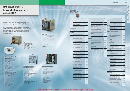
<strong>IZM</strong> <strong>circuit</strong>-<strong>breakers</strong><br />
<strong>IN</strong> <strong>switch</strong>-<strong>disconnec<strong>to</strong>rs</strong><br />
<strong>up</strong> <strong>to</strong> <strong>6300</strong> A<br />
Modern protection technology covering the<br />
rated current range from 630 A <strong>to</strong> <strong>6300</strong> A.<br />
This overview will assist you <strong>to</strong> efficiently use<br />
the Moeller concept for the open <strong>circuit</strong>-breaker<br />
<strong>IZM</strong>. It shows you a whole range of available<br />
options and the system involved for function<br />
enhancements.<br />
Measurement, signalling,<br />
communication<br />
- Communication module<br />
Part no. +<strong>IZM</strong>-COM-DP,<br />
Page 11/32<br />
- Measuring module<br />
Part no.: +<strong>IZM</strong>-XMH,<br />
Page 11/32<br />
- Display for universal <strong>circuit</strong>-breaker,<br />
Part no. +<strong>IZM</strong>-XAM,<br />
Page 11/26<br />
- Operations counter<br />
Page 11/38<br />
- Position signalling <strong>switch</strong>es<br />
For withdrawable unit<br />
Part no.: +<strong>IZM</strong>-XHIAV...<br />
Page 11/49<br />
- Auxiliary contacts<br />
(Trip-indicating, Availability signal,<br />
Spring charge state,<br />
Voltage release state)<br />
Part no.: +<strong>IZM</strong>-XHI...<br />
Page 11/36<br />
- Expansion modules<br />
Part no.: <strong>IZM</strong>-XEM-...<br />
Page 11/34<br />
High availability<br />
- Withdrawable units<br />
Part no.: +<strong>IZM</strong>...-XAV...<br />
Page 11/48<br />
- Arcing chamber covers<br />
Part no.: +<strong>IZM</strong>...-XKLA...-AV<br />
Page 11/49<br />
Comprehensive fixed<br />
mounted accessories<br />
- Main <strong>circuit</strong> terminals<br />
(V = vertical, F = front, A = flange)<br />
Part no.: +<strong>IZM</strong>...-XAT...V(F, A)...<br />
Page 11/50<br />
- Auxiliary springloaded terminals<br />
Part no.: +<strong>IZM</strong>-XKLZ...<br />
Page 11/38<br />
- Door sealing frames, external<br />
actuation, IP40<br />
Part no.: <strong>IZM</strong>-XRT<br />
Page 11/44<br />
- Protective cover, transparent, IP55<br />
Part no.: <strong>IZM</strong>-XDT<br />
Page 11/44<br />
Basic unit<br />
- Switching capacity 440 V AC,<br />
I cu = I cs from 50 <strong>to</strong> 100 kA<br />
- 3- or 4 pole<br />
- Electronic release for system<br />
protection, selective protection,<br />
universal protection and digital<br />
release with graphic display<br />
- Rated current In from 630 <strong>to</strong> <strong>6300</strong> A<br />
- Rated voltage U e 1000 V<br />
Part no.: +<strong>IZM</strong>...-...-X1000V<br />
Page 11/10<br />
Operate with comfort<br />
- Mo<strong>to</strong>r drives<br />
Part no.: +<strong>IZM</strong>-XM...<br />
Page 11/38<br />
- Parameter definition systems<br />
Part no.: <strong>IZM</strong>-XEM-...PG...<br />
Page 11/31<br />
- Shunt releases, Part no. +<strong>IZM</strong>-XA…<br />
Page 11/40<br />
- Closing releases<br />
Part no.: +<strong>IZM</strong>-XE...<br />
Page 11/40<br />
- Undervoltage releases<br />
Part no.: +<strong>IZM</strong>-XU...<br />
Page 11/42<br />
Circuit-<strong>breakers</strong>,<br />
<strong>switch</strong>-<strong>disconnec<strong>to</strong>rs</strong><br />
from 630 <strong>to</strong> <strong>6300</strong> A<br />
Technical overview<br />
Page<br />
<strong>IZM</strong> <strong>circuit</strong>-<strong>breakers</strong> 11/2<br />
<strong>IN</strong> <strong>switch</strong>-<strong>disconnec<strong>to</strong>rs</strong> 11/3<br />
Electronic releases for <strong>circuit</strong>-<strong>breakers</strong><br />
System overview<br />
Description<br />
Ordering<br />
11/4<br />
Circuit-<strong>breakers</strong> 11/6<br />
Circuit-breaker, <strong>switch</strong>-disconnec<strong>to</strong>r 11/8<br />
<strong>IZM</strong>1 <strong>circuit</strong>-<strong>breakers</strong>, 3 pole …<br />
… For system protection (A) 11/10<br />
… For selective protection (V) 11/10<br />
… For universal protection (U) 11/10<br />
… With digital release (D) 11/10<br />
<strong>IZM</strong>2 <strong>circuit</strong>-<strong>breakers</strong>, 3 pole …<br />
… For system protection (A) 11/12<br />
… For selective protection (V) 11/12<br />
… For universal protection (U) 11/12<br />
… With digital release (D) 11/12<br />
<strong>IZM</strong>3 <strong>circuit</strong>-<strong>breakers</strong>, 3 pole …<br />
… For selective protection (V) 11/14<br />
… For universal protection (U) 11/14<br />
… With digital release (D) 11/14<br />
<strong>IZM</strong>1 <strong>circuit</strong>-<strong>breakers</strong>, 4 pole …<br />
… For system protection (A) 11/16<br />
… For selective protection (V) 11/16<br />
… For universal protection (U) 11/16<br />
… With digital release (D) 11/16<br />
<strong>IZM</strong>2 <strong>circuit</strong>-<strong>breakers</strong>, 4 pole …<br />
… For system protection (A) 11/18<br />
… For selective protection (V) 11/18<br />
… For universal protection (U) 11/18<br />
… With digital release (D) 11/18<br />
<strong>IZM</strong>3 <strong>circuit</strong>-<strong>breakers</strong>, 4 pole …<br />
… For selective protection (V) 11/20<br />
… For universal protection (U) 11/20<br />
… With digital release (D) 11/20<br />
Ordering<br />
Page<br />
Switch-<strong>disconnec<strong>to</strong>rs</strong>, 3- and 4 pole 11/22<br />
Increasing the rated operational<br />
voltage <strong>to</strong> 1000 V AC<br />
11/24<br />
Electronic overcurrent releases 11/25<br />
Test units, rated current module 11/25<br />
Earth-fault protection 11/26<br />
Accessories for electronic overcurrent 11/26<br />
releases<br />
Description<br />
Ordering<br />
Components for communication 11/29<br />
Parameter definition systems 11/31<br />
Communication and measuring 11/32<br />
function<br />
Expansion modules 11/34<br />
Auxiliary contact 11/36<br />
Mo<strong>to</strong>r opera<strong>to</strong>r 11/38<br />
Closing release, trip block 11/40<br />
Electrically ON, Emergency-S<strong>to</strong>p,<br />
brackets, door seals<br />
11/44<br />
Engineering<br />
Ordering<br />
Control <strong>circuit</strong> plug terminal<br />
assignment plan<br />
Page<br />
11/45<br />
Locking devices 11/46<br />
Locking arrangements 11/47<br />
Withdrawable units 11/48<br />
Ordering, withdrawable units<br />
Ordering<br />
Engineering<br />
Withdrawable unit 11/48<br />
Fixed mounting conversion kit for<br />
withdrawable units<br />
11/49<br />
Position signalling <strong>switch</strong> 11/49<br />
Shutters 11/49<br />
Arcing chamber cover 11/49<br />
Coding system 11/49<br />
Connection systems for fixed<br />
mounting<br />
Connection system for withdrawable<br />
unit<br />
11/50<br />
11/52<br />
Selectivity tables 415 V AC 11/54<br />
Tripping characteristics 11/61<br />
Technical data<br />
Permissible continuous current 11/65<br />
Circuit-<strong>breakers</strong> 11/66<br />
Switch-disconnec<strong>to</strong>r 11/72<br />
Control unit 11/76<br />
Auxiliary contact 11/76<br />
Voltage release 11/77<br />
Mo<strong>to</strong>r opera<strong>to</strong>r 11/77<br />
Current consumption 11/78<br />
Safety clearances 11/78<br />
Dimensions<br />
External dimensions, door cut-out 11/80<br />
Fixed mounting and optional 11/81<br />
connection terminals, 3 and 4-pole<br />
Withdrawable units and optional<br />
connection terminals, 3 and 4-pole<br />
11/83<br />
Fixed mounted, 3 and 4 pole 11/85<br />
Optional connection terminals 11/86<br />
Measuring transformers, voltage 11/91<br />
releases<br />
Circuit-Breaker <strong>IZM</strong> from 630 A <strong>to</strong> <strong>6300</strong> A,<br />
Switch-Disconnec<strong>to</strong>r <strong>IN</strong> from 630 A <strong>to</strong> <strong>6300</strong> A<br />
For Moeller Electric Sales and S<strong>up</strong>port call KMparts.com (866) 595-9616
11/2<br />
Technical overview<br />
Circuit-breaker<br />
Circuit-<strong>breakers</strong>, <strong>switch</strong>-<strong>disconnec<strong>to</strong>rs</strong><br />
from 630 A <strong>to</strong> <strong>6300</strong> A<br />
Circuit-breaker<br />
with main <strong>switch</strong> and isolating characteristics<br />
(in combination with the “interlock in OFF” facility)<br />
from 630 … <strong>6300</strong> A<br />
<strong>IZM</strong><br />
<strong>IZM</strong><br />
Rated current n =<br />
rated uninterr<strong>up</strong>ted current I u<br />
A<br />
Basic<br />
<strong>switch</strong>ing capacity (B)<br />
Moeller HPL0211-2007/2008<br />
Normal <strong>switch</strong>ing capacity<br />
(N)<br />
Rated ultimate short-<strong>circuit</strong> breaking capacity I cu at rated operational voltage U e<br />
440 V<br />
cu = cs<br />
690 V<br />
cu = cs<br />
kA<br />
440 V<br />
cu = cs<br />
kA<br />
690 V<br />
cu = cs<br />
kA<br />
High <strong>switch</strong>ing capacity (H)<br />
440 V<br />
cu = cs<br />
kA<br />
690 V<br />
cu = cs<br />
kA<br />
http://catalog.moeller.net<br />
1000 V<br />
cu = cs<br />
kA<br />
<strong>IZM</strong>…1(-4)-…<br />
50 42 65 50<br />
a<br />
a<br />
<strong>IZM</strong>…2(-4)-…<br />
a<br />
a<br />
<strong>IZM</strong>…3(-4)-…<br />
<strong>IZM</strong> … … … … …<br />
Switching capacity<br />
see above B<br />
see above N<br />
see above H<br />
Frame size<br />
630 … 1600 A 1<br />
800 … 3200 A 2<br />
4000 … <strong>6300</strong> A 3<br />
Poles<br />
3 pole ()<br />
4 pole -4<br />
Electronic releases<br />
page 11/6<br />
Standard release<br />
Selective-operating release<br />
Universal release<br />
Digital release<br />
A<br />
V<br />
U<br />
D<br />
Rated current in A<br />
Frame size 1 630…1600<br />
Frame size 2 800…3200<br />
Frame size 3 4000…<strong>6300</strong><br />
For Moeller Electric Sales and S<strong>up</strong>port call KMparts.com (866) 595-9616
For Moeller Electric Sales and S<strong>up</strong>port call KMparts.com (866) 595-9616<br />
Switch-<strong>disconnec<strong>to</strong>rs</strong><br />
with main <strong>switch</strong> and isolating characteristics (in<br />
combination with the “interlock in OFF” facility)<br />
from 630 … <strong>6300</strong> A<br />
<strong>IN</strong><br />
Rated current n =<br />
rated uninterr<strong>up</strong>ted current u<br />
A<br />
Basic<br />
<strong>switch</strong>ing capacity (B)<br />
Normal<br />
<strong>switch</strong>ing capacity (N)<br />
Rated ultimate short-<strong>circuit</strong> making capacity cm<br />
rated short-time withstand current cw t = 1 s<br />
cm<br />
kA<br />
cw<br />
kA<br />
cm<br />
kA<br />
Technical overview<br />
Switch-<strong>disconnec<strong>to</strong>rs</strong> <strong>IN</strong><br />
cw<br />
kA<br />
High<br />
<strong>switch</strong>ing capacity (H)<br />
cm<br />
kA<br />
cw<br />
kA<br />
<strong>IN</strong><br />
11/3<br />
Circuit-<strong>breakers</strong>, <strong>switch</strong>-<strong>disconnec<strong>to</strong>rs</strong><br />
from 630 A <strong>to</strong> <strong>6300</strong> A<br />
<strong>IN</strong>…1(-4)-…<br />
630 … 1600 105 42 143 50<br />
page 11/22<br />
<strong>IN</strong>…2(-4)-…<br />
800 … 3200 121 55 176 65 220 80<br />
page 11/22<br />
<strong>IN</strong>H3(-4)-…<br />
4000 … 5000 220 80<br />
<strong>6300</strong> 220 100<br />
page 11/23
For Moeller Electric Sales and S<strong>up</strong>port call KMparts.com (866) 595-9616<br />
Circuit-<strong>breakers</strong>, <strong>switch</strong>-<strong>disconnec<strong>to</strong>rs</strong><br />
from 630 A <strong>to</strong> <strong>6300</strong> A<br />
11/4<br />
Feature overview<br />
Electronic releases for <strong>circuit</strong>-<strong>breakers</strong><br />
<strong>IZM</strong><br />
<strong>IZM</strong> …-A…<br />
System protection<br />
630 … 3200 A<br />
<strong>IZM</strong> …-V…<br />
Selectivelyopening<br />
<strong>circuit</strong><strong>breakers</strong><br />
630 … <strong>6300</strong> A<br />
Moeller HPL0211-2007/2008<br />
<strong>IZM</strong> …-U…<br />
Universal<br />
protection<br />
630 … <strong>6300</strong> A<br />
<strong>IZM</strong> …-D…<br />
Digital release<br />
630 … <strong>6300</strong> A<br />
http://catalog.moeller.net<br />
<strong>IZM</strong> …-D… +<br />
<strong>IZM</strong>-XZMR<br />
Digital release<br />
exclusively featuring<br />
external parameterization<br />
access<br />
630 … <strong>6300</strong> A<br />
Basic protective functions<br />
Overload protection I r L K K K K K<br />
Adjustable delay time t r … … K K K<br />
Short-time delayed short-<strong>circuit</strong> protection I sd S … K K K K<br />
Non-delayed short-<strong>circuit</strong> protection I i I K K 2) K K K<br />
Neutral conduc<strong>to</strong>r protection N … k K K K<br />
Earth-fault protection G … k k k k<br />
Additional functions<br />
N conduc<strong>to</strong>r protection can be … k K K K<br />
Short time delayed short-<strong>circuit</strong> protection can be<br />
… … K K K<br />
activated/deactivated<br />
Non-delayed short-<strong>circuit</strong> protection can be<br />
… … K K K<br />
activated/deactivated<br />
Thermal memory can be activated/deactivated … … K K K<br />
Load moni<strong>to</strong>ring … … K K K<br />
Leading “L” trip signal, 200 ms … … K K K<br />
Short-time delayed short-<strong>circuit</strong> protection I 2 t can be … … K K K<br />
selected<br />
Overload protection can be set <strong>to</strong> I 4 t … … K K K<br />
Overload protection can be activated/deactivated … … … K K<br />
N conduc<strong>to</strong>r protection adjustable … … K K K<br />
Earth-fault protection convertible <strong>to</strong> I 2 t … … K K K<br />
Earth fault alarm … … k k k<br />
Selectable parameter sets … … … K K<br />
Zone-selective interlocking … … k k k<br />
Parametric programming and visualization<br />
Parametric programming via rotary coding <strong>switch</strong> K K K … …<br />
Parametric programming via communication<br />
… … … K K<br />
(absolute values)<br />
Parametric programming via communication … … … K …<br />
Remote parameter definition of the basic functions … … … K K<br />
Remote parameter definition of additional functions … … K K K<br />
Setting using parameter assignment module Comm … … … K K<br />
<strong>IZM</strong>-XEM-PG or PROFIBUS-DP 1)<br />
Menu-assisted setting directly on release 1) Menu … … … K …<br />
Alphanumeric LCD (4-line display) … … k … …<br />
Graphic LCD … … … K …<br />
Other<br />
Connection feature for an external 24 V DC power<br />
s<strong>up</strong>ply<br />
… … K K K<br />
Notes<br />
1) Step size for setting Menu/Comm or Comm<br />
Setting range Step width<br />
0 … 1<br />
1 … 100<br />
100 … 500<br />
500 … 1000<br />
1000 … 1600<br />
1600 … 10 000<br />
10 000 … max.<br />
0.1<br />
1<br />
5<br />
10<br />
50<br />
100<br />
1000<br />
K<br />
k<br />
standard<br />
optional<br />
2) Fixed at I i f 20 x I n , max. 50 kA
For Moeller Electric Sales and S<strong>up</strong>port call KMparts.com (866) 595-9616<br />
http://catalog.moeller.net<br />
Moeller HPL0211-2007/2008<br />
<strong>IZM</strong> …-A…<br />
System protection<br />
630 … 3200 A<br />
Technical overview<br />
Electronic releases for <strong>circuit</strong>-<strong>breakers</strong><br />
<strong>IZM</strong> …-V…<br />
Selectivelyopening<br />
<strong>circuit</strong><strong>breakers</strong><br />
630 … <strong>6300</strong> A<br />
<strong>IZM</strong> …-U…<br />
Universal<br />
protection<br />
630 … <strong>6300</strong> A<br />
<strong>IZM</strong> …-D…<br />
<strong>IZM</strong>…<br />
Digital release<br />
630 … <strong>6300</strong> A<br />
11/5<br />
<strong>IZM</strong> …-D… +<br />
<strong>IZM</strong>-XZMR<br />
Digital release<br />
exclusively featuring<br />
external parameterization<br />
access<br />
630 … <strong>6300</strong> A<br />
Circuit-<strong>breakers</strong>, <strong>switch</strong>-<strong>disconnec<strong>to</strong>rs</strong><br />
from 630 A <strong>to</strong> <strong>6300</strong> A<br />
Measuring function<br />
“harmonic” measuring function … … k k k<br />
Communication<br />
Internal system bus … … K K K<br />
PROFIBUS-DP communication … … k k K<br />
Communication using Ethernet … … k k k<br />
LED display features<br />
Release active K K K K K<br />
Alarm 100 % I r K K K K K<br />
Control unit error message K K K K K<br />
Overload trip L … K K K K<br />
Short-time delayed short-<strong>circuit</strong> trip S … K K K K<br />
Non-delayed short-<strong>circuit</strong> trip I … K K K K<br />
Neutral conduc<strong>to</strong>r trip N … K 1) K K K<br />
Earth-fault protection trip G … K 1) K 2) K 2) K 2)<br />
Earth-fault protection alarm G … … K 3) K 3) K 2)<br />
Trip by extended protective function … … K K K<br />
Communication … … K K K<br />
Signals via signalling <strong>switch</strong> with external<br />
system bus modules (relay)<br />
Overload warning 100 % I r … … K K K<br />
Load shedding, load pick-<strong>up</strong> … … K K K<br />
Leading overload signal 100 ms … … K K K<br />
Temperature alarm … … K K K<br />
Phase imbalance … … K K K<br />
Overload trip L … … K K K<br />
Short-time delayed short-<strong>circuit</strong> trip S … … K K K<br />
Non-delayed short-<strong>circuit</strong> trip I … … K K K<br />
Neutral conduc<strong>to</strong>r trip N … … K K K<br />
Earth-fault protection trip G … … K 2) K 2) K<br />
Earth-fault protection alarm G … … K 3) K 3) K<br />
Auxiliary relay … … K K K<br />
Control unit error message … … K K K<br />
Notes<br />
1) (only possible with option +<strong>IZM</strong>-XT)<br />
2) (only possible with option (+)<strong>IZM</strong>U-XT)<br />
3) (only possible with option (+)<strong>IZM</strong>D-XT(A))<br />
K<br />
k<br />
standard<br />
optional
For Moeller Electric Sales and S<strong>up</strong>port call KMparts.com (866) 595-9616<br />
11/6<br />
System overview<br />
Circuit-<strong>breakers</strong><br />
Circuit-<strong>breakers</strong>, <strong>switch</strong>-<strong>disconnec<strong>to</strong>rs</strong><br />
from 630 A <strong>to</strong> <strong>6300</strong> A<br />
2<br />
<strong>IZM</strong><br />
5<br />
5<br />
3<br />
4<br />
5<br />
Moeller HPL0211-2007/2008<br />
5<br />
5<br />
6<br />
http://catalog.moeller.net<br />
7<br />
7<br />
2<br />
1<br />
8<br />
8<br />
17<br />
16<br />
15<br />
14<br />
0 1695<br />
10<br />
9<br />
11<br />
11<br />
11<br />
11<br />
13<br />
12
System overview<br />
Circiut-<strong>breakers</strong><br />
11/7<br />
http://catalog.moeller.net<br />
Base units<br />
Circuit-<strong>breakers</strong> <strong>IZM</strong> 1<br />
Rated current from 630 … <strong>6300</strong> A<br />
4-stage <strong>switch</strong>ing capacity<br />
4 release types for different protection<br />
and indication functions<br />
3 and 4-pole versions<br />
a page 11/10<br />
Communication<br />
Communication module 3<br />
for PROFIBUS-DP<br />
a page 11/32<br />
External expansion modules 2<br />
a page 11/35<br />
Electronic releases 11<br />
Standard protection functions<br />
Optional protection functions<br />
Additional functions<br />
Parametric programming and visualization<br />
Measuring functions<br />
Communication<br />
a page 11/24<br />
Parameter assignment module 12<br />
a page 11/31<br />
Moeller HPL0211-2007/2008<br />
Add-on functions<br />
Position signalling <strong>switch</strong> 4<br />
Module for withdrawable unit<br />
Module 1<br />
• Connected position: 1 changeover contact<br />
• Test position: 1 changeover contact<br />
• Disconnected position: 1 changeover<br />
contact<br />
Module 2<br />
• Connected position: 3 changeover contacts<br />
• Test position: 2 changeover contacts<br />
• Disconnected position: 1 changeover<br />
contact<br />
a page 11/49<br />
Control <strong>circuit</strong> plugs 7<br />
Screw terminals Spring-loaded terminals<br />
a page 11/38<br />
Auxiliary contacts 8<br />
Normal auxiliary contacts with 2 N/C and<br />
2 N/O contacts (standard)<br />
2 N/C contacts and 2 N/O contacts additionally<br />
possible<br />
Ready-<strong>to</strong>-close auxiliary contacts<br />
Trip indication<br />
Spring energy s<strong>to</strong>re status signal<br />
Voltage release status signal<br />
a page 11/37<br />
Mo<strong>to</strong>r opera<strong>to</strong>r 9<br />
Au<strong>to</strong>matic charging of the s<strong>to</strong>red energy<br />
mechanism for ON and OFF operations<br />
Mo<strong>to</strong>r cut-off <strong>switch</strong><br />
a page 11/38<br />
<strong>IZM</strong><br />
Mounting accessories<br />
Terminations 5<br />
Horizontal connection (standard)<br />
Vertical connection<br />
Front connection (single hole fitting,<br />
double hole fitting)<br />
Flanged connection (on withdrawable<br />
units)<br />
a page 11/50<br />
Replacing the <strong>switch</strong> by insertion and<br />
withdrawal<br />
3 positions, lockable<br />
• Connected position<br />
• Test position<br />
• Disconnected position<br />
Indication of the positions by position<br />
signalling <strong>switch</strong><br />
Arcing chamber cover for reduction of the<br />
safety clearance<br />
Shutter for au<strong>to</strong>matic locking of the input<br />
and output contacts within the withdrawable<br />
unit, lockable<br />
Replacing the <strong>switch</strong> by insertion and<br />
withdrawal<br />
a page 11/48<br />
Door seal 14<br />
For door mounting, degree of protection<br />
IP40<br />
Protective cover <strong>to</strong> IP55<br />
a page 11/44<br />
6<br />
Circuit-<strong>breakers</strong>, <strong>switch</strong>-<strong>disconnec<strong>to</strong>rs</strong><br />
from 630 A <strong>to</strong> <strong>6300</strong> A<br />
Earth-fault protection module 13<br />
Earth-fault alarm module<br />
a page 11/26<br />
Operations counter 10<br />
a page 11/38<br />
Rated current modules 15<br />
Rating plug<br />
a page 11/25<br />
Emergency-S<strong>to</strong>p mushroom actua<strong>to</strong>r 16<br />
a page 11/44<br />
Voltage release 17<br />
Closing release<br />
Shunt release<br />
Undervoltage release<br />
• Non-delayed<br />
• Off-delayed<br />
a page 11/40<br />
For Moeller Electric Sales and S<strong>up</strong>port call KMparts.com (866) 595-9616
For Moeller Electric Sales and S<strong>up</strong>port call KMparts.com (866) 595-9616<br />
11/8<br />
Description<br />
Circuit-<strong>breakers</strong>, <strong>switch</strong>-<strong>disconnec<strong>to</strong>rs</strong><br />
Circuit-<strong>breakers</strong>, <strong>switch</strong>-<strong>disconnec<strong>to</strong>rs</strong><br />
from 630 A <strong>to</strong> <strong>6300</strong> A<br />
<strong>IZM</strong>, <strong>IN</strong><br />
Moeller HPL0211-2007/2008<br />
http://catalog.moeller.net<br />
<strong>IZM</strong> <strong>circuit</strong>-<strong>breakers</strong><br />
The <strong>IZM</strong> from Moeller embodies a concept for open <strong>circuit</strong>-<strong>breakers</strong> that exceeds the<br />
standard throughout the world. Based on state-of-the-art system engineering, these<br />
<strong>switch</strong>es open <strong>up</strong> a new dimension in the rated current range from<br />
630 <strong>to</strong> <strong>6300</strong> A. They excel not only for their performance, but also for their functionality,<br />
especially in their communications capabilities and their ease of handling<br />
and installation.<br />
A comprehensive opera<strong>to</strong>r manual is s<strong>up</strong>plied with each device.<br />
Applications<br />
Co<strong>up</strong>ler <strong>switch</strong>es: Beside the <strong>IZM</strong> <strong>circuit</strong>-<strong>breakers</strong>, <strong>IN</strong> <strong>switch</strong>-<strong>disconnec<strong>to</strong>rs</strong> are available.<br />
These are used, for example, as co<strong>up</strong>ler <strong>switch</strong>es between different power<br />
s<strong>up</strong>plies.<br />
Main <strong>switch</strong>es: You can use both <strong>IN</strong> <strong>switch</strong>-<strong>disconnec<strong>to</strong>rs</strong> and <strong>IZM</strong> <strong>circuit</strong>-<strong>breakers</strong><br />
as mains isolating <strong>switch</strong>es. When fitted with a lockable handle, all <strong>IZM</strong> <strong>circuit</strong>-<strong>breakers</strong><br />
(and <strong>IN</strong> <strong>switch</strong>-<strong>disconnec<strong>to</strong>rs</strong>) fulfil the main <strong>switch</strong> and isolating characteristics<br />
according <strong>to</strong> IEC/EN 60204-1. Depending on the type of apparatus <strong>to</strong> be<br />
protected, the tasks of the <strong>circuit</strong>-<strong>breakers</strong> can be split in<strong>to</strong> four main applications:<br />
• System protection<br />
• Mo<strong>to</strong>r protection<br />
• Transformer protection<br />
• Genera<strong>to</strong>r protection.<br />
These key applications make different demands on the <strong>switch</strong>es, which are met with<br />
a range of control units.<br />
Switches with closing release are suitable for synchronization tasks.<br />
Safety and reliability<br />
Numerous locking features are provided or can be fitted by the user, on the one<br />
hand <strong>to</strong> protect the <strong>switch</strong> and system from unauthorised <strong>switch</strong>ing, and on the<br />
other for the protection of maintenance and operating personnel.<br />
Further safety features are:<br />
• Power feed from <strong>to</strong>p or bot<strong>to</strong>m as required<br />
• Standard locking facility for the withdrawable unit when the <strong>switch</strong> is removed<br />
• Standard locking facility for the <strong>switch</strong> in withdrawable unit <strong>to</strong> prevent removal<br />
• High degree of protection with IP 55 terminal cover<br />
• Standard with mechanical closing lockout after overload or short-<strong>circuit</strong> release<br />
• The operating panel cannot be removed when the <strong>switch</strong> is operational<br />
• Delivery including all auxiliary <strong>circuit</strong> connec<strong>to</strong>rs corresponding <strong>to</strong> built-in features<br />
including coding device <strong>to</strong> prevent mix-<strong>up</strong> of plug-connec<strong>to</strong>rs with fixed<br />
mounted <strong>breakers</strong><br />
• Devices with +<strong>IZM</strong>-XCOM-DP communication interfacing feature temperature<br />
sensors on the built-in micro<strong>switch</strong> detection units (XBSS) and on the communication<br />
module.<br />
Standard version<br />
<strong>IZM</strong> <strong>circuit</strong>-breaker has the following standard equipment:<br />
• Electronic overcurrent releases<br />
• Rated current module (with the exception of <strong>IZM</strong>…-A…)<br />
• Mechanical ON and mechanical OFF <strong>switch</strong><br />
• Manual drive for charging the spring-operated s<strong>to</strong>red energy mechanism<br />
• Switch position indication 0 / I<br />
• Ready indication OK<br />
• Charge state display<br />
• Auxiliary <strong>circuit</strong> <strong>switch</strong> 2 M + 2 B<br />
• Horizontal main terminals on rear with fixed mounted and with withdrawable<br />
units <strong>up</strong> <strong>to</strong> 5000 A and on rear with vertical main terminals at <strong>6300</strong> A<br />
• With 4-pole <strong>switch</strong>es the 4th pole (N) is fitted on the left and can be loaded <strong>to</strong><br />
100 %<br />
• Display of the contact erosion of the main contacts<br />
• Auxiliary current plug system with screw terminals. The <strong>switch</strong> is always equipped<br />
with the required number of auxiliary current plugs.<br />
• Mechanically tripped display of the overcurrent release system<br />
• Mechanical reclosing lockout after trip<br />
• Operation manual in English<br />
Additional with withdrawable units:<br />
• Main contacts: Laminated contacts on the back plate of the withdrawable unit,<br />
contact pin on basic unit<br />
• Position display with operating console of the plug-in <strong>switch</strong><br />
• Captive crank handle for <strong>switch</strong> movement with withdrawable system<br />
• Withdrawable unit with guide rails for simple handling<br />
• Locking facility for <strong>switch</strong> movement in the withdrawable unit<br />
• The <strong>switch</strong> cannot be moved in the withdrawable unit in the on state<br />
• Rated current coding between the withdrawable unit and the <strong>switch</strong>.<br />
Design<br />
The compact design of the <strong>circuit</strong>-<strong>breakers</strong> provides optimum utilization of the available<br />
space, allowing control panels <strong>to</strong> be equipped more efficiently. The <strong>IZM</strong> for a<br />
rated current <strong>up</strong> <strong>to</strong> <strong>6300</strong> A, for example, can be installed in am 800 mm wide control<br />
panel field. Switches with a rated current of 1600 A need only a 400 mm field.<br />
Operating panel<br />
The operating panel is designed <strong>to</strong> ensure that it can protrude through a cut-out in<br />
the door and that all operation elements and displays can be accessed when the<br />
control panel door is closed. The operating panels of all <strong>switch</strong>es (fixed mounted/<br />
withdrawable, 3/4-pole) are identical. The operating panel provides IP20 degree of<br />
protection.
For Moeller Electric Sales and S<strong>up</strong>port call KMparts.com (866) 595-9616<br />
http://catalog.moeller.net<br />
Current range<br />
Moeller HPL0211-2007/2008<br />
The new open <strong>circuit</strong>-breaker <strong>IZM</strong> covers the entire range from 800 A … <strong>6300</strong> A<br />
with just two frame sizes. The compact frame size <strong>IZM</strong>1 extends the rated current<br />
range downwards <strong>to</strong> 630 A. If required, the range can be extended <strong>to</strong> 250 A by exchanging<br />
the rating plug. And all this with a setting range of 0.4 … 1 x In.<br />
Dimensions<br />
The <strong>IZM</strong> devices have the same height and depth across their entire current range.<br />
Only their device varies depending on the number of poles and the frame size.<br />
Connection by<br />
As standard, <strong>IZM</strong> <strong>circuit</strong>-<strong>breakers</strong> are fitted with horizontal connections. Optionally,<br />
the following connections are possible: vertical connections, connections that are<br />
accessible from the front and flanged connections.<br />
Control units<br />
The <strong>IZM</strong> features microprocessor-controlled control units as standard. Five different<br />
control units are available for selection and thus offer optimum protection for your<br />
system: From simple system protection with overload and short-<strong>circuit</strong> release extending<br />
<strong>to</strong> a digital <strong>circuit</strong>-breaker with graphic display and the option of setting <strong>up</strong><br />
time-discriminating networks.<br />
Control <strong>circuit</strong> connections<br />
The built-in auxiliary <strong>switch</strong>es are connected <strong>to</strong> the male connec<strong>to</strong>r on the <strong>switch</strong>.<br />
Irrespective of the mounting type, the cus<strong>to</strong>mer connects the auxiliary power <strong>circuit</strong>s<br />
<strong>to</strong> the control <strong>circuit</strong> plugs at the <strong>to</strong>p of the <strong>circuit</strong>-breaker. The standard terminals<br />
are screw-type; spring-loaded terminals are optional.<br />
ON fixed mounting units, the control <strong>circuit</strong> plugs are fitted directly <strong>to</strong> the plug connec<strong>to</strong>rs<br />
on the <strong>switch</strong> and are coded against accidental reversal.<br />
To allow withdrawable units <strong>to</strong> be moved, a sliding contact module is fitted between<br />
<strong>switch</strong> and mounting. The sliding contact module allows a secure connection of the<br />
control <strong>circuit</strong> cable connec<strong>to</strong>rs in the “connected” and “test” positions of the<br />
<strong>switch</strong>.<br />
Modular design<br />
Because components are installed from the front, retrofitting accessories is especially<br />
quick and easy. This allows you <strong>to</strong> respond flexibly <strong>to</strong> changing requirements<br />
within your system.<br />
Communication-capability<br />
With their communication-capability, the <strong>IZM</strong> <strong>circuit</strong>-<strong>breakers</strong> open <strong>up</strong> new possibilities<br />
in power distribution. Providing and transmitting all important operational information,<br />
they increase system transparency and shorten the response times <strong>to</strong><br />
states such as overcurrent, phase asymmetry and overvoltage. A rapid intervention<br />
in a process can, for example, prevent downtimes and help <strong>to</strong> schedule maintenance<br />
activities and therefore boost plant availability.<br />
Internal system bus<br />
The <strong>IZM</strong> universal and digital <strong>circuit</strong>-<strong>breakers</strong> contain an internal system bus as<br />
standard, which connects all intelligent components of the <strong>circuit</strong>-breaker.<br />
Through the communications interface, the information from the intelligent components<br />
can then be transmitted through PROFIBUS-DP, for example with the <strong>IZM</strong>-<br />
XCOM communication module.<br />
Expansion modules for the internal system bus:<br />
External add-on modules can be connected <strong>to</strong> the <strong>IZM</strong> <strong>circuit</strong>-<strong>breakers</strong> through the<br />
internal system bus without extensive additional wiring. Digital input modules and<br />
digital and analog output modules are available for this purpose. A further module<br />
implements reduced-time selectivity control between <strong>IZM</strong> <strong>circuit</strong>-<strong>breakers</strong>.<br />
Description<br />
Circuit-<strong>breakers</strong>, <strong>switch</strong>-<strong>disconnec<strong>to</strong>rs</strong><br />
Selection criteria for <strong>IZM</strong> <strong>circuit</strong>-<strong>breakers</strong><br />
11/9<br />
Fundamental criteria for the selection of <strong>circuit</strong>-<strong>breakers</strong>:<br />
• Max. short-<strong>circuit</strong> at the point of installation of <strong>circuit</strong>-breaker I k max: this value<br />
determines the short-<strong>circuit</strong> breaking capacity or the short-<strong>circuit</strong> current carrying<br />
capacity of the <strong>circuit</strong>-breaker. It is compared with the value I cu , I cs , I cw of<br />
the <strong>switch</strong> and mainly determines the size of the <strong>switch</strong> a technical data.<br />
• Rated current I n which should flow through the respective branch <strong>circuit</strong>: this<br />
value may not be greater than the maximum <strong>switch</strong> rated current of the <strong>circuit</strong>breaker.<br />
The rated current is defined with the <strong>IZM</strong> with the rated current module<br />
(exception: overcurrent release for system protection XZMA).<br />
• Ambient temperature of the <strong>circuit</strong>-breaker: this is generally the internal control<br />
panel temperature. Observe the derating table with increased ambient temperature<br />
a Technical data.<br />
• Circuit-breaker type: fixed mounted or withdrawable, 3 or 4-pole.<br />
• Minimum short-<strong>circuit</strong> current, which flows through the <strong>switch</strong>gear: The release<br />
must recognize this value as a short-<strong>circuit</strong> and may react with a trip.<br />
• Protection functions of the <strong>circuit</strong>-breaker: This is determined by the selection<br />
of the respective overcurrent release.<br />
Documentation<br />
Operating manual AWB1230-1407D/GB, part no. 232792<br />
Approvals<br />
<strong>IZM</strong>, <strong>IN</strong><br />
Approved <strong>circuit</strong>-<strong>breakers</strong> <strong>IZM</strong> can be found under “Approvals for world markets”.<br />
Circuit-<strong>breakers</strong>, <strong>switch</strong>-<strong>disconnec<strong>to</strong>rs</strong><br />
from 630 A <strong>to</strong> <strong>6300</strong> A
For Moeller Electric Sales and S<strong>up</strong>port call KMparts.com (866) 595-9616<br />
Circuit-<strong>breakers</strong>, <strong>switch</strong>-<strong>disconnec<strong>to</strong>rs</strong><br />
from 630 A <strong>to</strong> <strong>6300</strong> A<br />
11/10<br />
Ordering<br />
Circuit-<strong>breakers</strong>, 3-pole<br />
<strong>IZM</strong>...1<br />
Moeller HPL0211-2007/2008<br />
http://catalog.moeller.net<br />
http://catalog.moeller.net<br />
Rating data Setting range Basic <strong>switch</strong>ing capacity (B) Normal <strong>switch</strong>ing capacity (N)<br />
Rated current = rated<br />
uninterr<strong>up</strong>ted current<br />
Overload<br />
releases<br />
Short-<strong>circuit</strong> releases I cu = I cs = 50kA at 415 V 50/60 Hz I cu = I cs = 65kA at 415 V 50/60 Hz<br />
Delayed Non-delayed Part no.<br />
I n = I u I r I sd I i<br />
Article no.<br />
A A A A<br />
I<br />
I<br />
<strong>IZM</strong>…1-…<br />
Circuit-<strong>breakers</strong> for distribution <strong>circuit</strong> protection (A)<br />
630 315 – 630 1260 … 5040 <strong>IZM</strong>B1-A630<br />
229889<br />
800 400 – 800 1600 … 6400 <strong>IZM</strong>B1-A800<br />
229890<br />
1000 500 – 1000 2000 … 8000 <strong>IZM</strong>B1-A1000<br />
229891<br />
1250 625 – 1250 2500 … 10000 <strong>IZM</strong>B1-A1250<br />
229892<br />
1600 800 – 1600 3200 … 12800 <strong>IZM</strong>B1-A1600<br />
229893<br />
Circuit-breaker for selective operation (V) and mo<strong>to</strong>r protection<br />
630 252 – 630 788 … 7560 12600 <strong>IZM</strong>B1-V630<br />
229900<br />
800 320 – 800 1000 … 9600 16000 <strong>IZM</strong>B1-V800<br />
229901<br />
1000 400 – 1000 1250 … 12000 20000 <strong>IZM</strong>B1-V1000<br />
229902<br />
1250 500 – 1250 1563 … 15000 25000 <strong>IZM</strong>B1-V1250<br />
229903<br />
1600 640 – 1600 2000 … 19200 32000 <strong>IZM</strong>B1-V1600<br />
229904<br />
Circuit-breaker for universal protection (U) and mo<strong>to</strong>r protection<br />
630 252 – 630 788 … 7560 945 … 7560, OFF <strong>IZM</strong>B1-U630<br />
229913<br />
800 320 – 800 1000 … 9600 1200 – 9600 , OFF <strong>IZM</strong>B1-U800<br />
229914<br />
1000 400 – 1000 1250 … 12000 1500 – 12000 , OFF <strong>IZM</strong>B1-U1000<br />
229915<br />
1250 500 – 1250 1563 … 15000 1875 … 15000, OFF <strong>IZM</strong>B1-U1250<br />
229916<br />
1600 640 – 1600 2000 … 19200 2400 – 19200 , OFF <strong>IZM</strong>B1-U1600<br />
229917<br />
Digital <strong>circuit</strong>-breaker (D) incl. graphic display<br />
630 252 – 630 1.25 x I n – 0.8 x I cw 1.5 x I n – 0.8 x I cs <strong>IZM</strong>B1-D630<br />
229923<br />
800 320 – 800 <strong>IZM</strong>B1-D800<br />
229927<br />
1000 400 – 1000 <strong>IZM</strong>B1-D1000<br />
229930<br />
1250 500 – 1250 <strong>IZM</strong>B1-D1250<br />
229931<br />
1600 640 – 1600 <strong>IZM</strong>B1-D1600<br />
229932<br />
Price<br />
see price list<br />
Std. pack<br />
Part no.<br />
Article no.<br />
1 off <strong>IZM</strong>N1-A630<br />
229894<br />
<strong>IZM</strong>N1-A800<br />
229895<br />
<strong>IZM</strong>N1-A1000<br />
229896<br />
<strong>IZM</strong>N1-A1250<br />
229898<br />
<strong>IZM</strong>N1-A1600<br />
229899<br />
1 off <strong>IZM</strong>N1-V630<br />
229905<br />
<strong>IZM</strong>N1-V800<br />
229906<br />
<strong>IZM</strong>N1-V1000<br />
229907<br />
<strong>IZM</strong>N1-V1250<br />
229908<br />
<strong>IZM</strong>N1-V1600<br />
229909<br />
1 off <strong>IZM</strong>N1-U630<br />
229918<br />
<strong>IZM</strong>N1-U800<br />
229919<br />
<strong>IZM</strong>N1-U1000<br />
229920<br />
<strong>IZM</strong>N1-U1250<br />
229921<br />
<strong>IZM</strong>N1-U1600<br />
229922<br />
1 off <strong>IZM</strong>N1-D630<br />
229933<br />
<strong>IZM</strong>N1-D800<br />
229934<br />
<strong>IZM</strong>N1-D1000<br />
229935<br />
<strong>IZM</strong>N1-D1250<br />
229936<br />
<strong>IZM</strong>N1-D1600<br />
229937<br />
Price<br />
see price list<br />
Moeller HPL0211-2007/2008<br />
Std. pack<br />
Notes<br />
1 off • Adjustable overload release I r = 0.5 – 1 x I n<br />
•Delay time t r = 10s at 6 x I r<br />
• Adjustable non-delayed short-<strong>circuit</strong> release I i = 2 – 8 x I n<br />
1 off • Adjustable overload release I r = 0.4 – 1 x I n<br />
•Delay time t r = 10s at 6 x I r<br />
• Adjustable delayed short-<strong>circuit</strong> release I sd = 1.25 – 12 x I n<br />
•Delay time t sd = 0, 20 (mo<strong>to</strong>r protection), 100, 200, 300, 400 ms<br />
• Non-delayed short-<strong>circuit</strong> release I i f 20 x I n<br />
Ordering<br />
Circuit-<strong>breakers</strong>, 3-pole<br />
<strong>IZM</strong>...1<br />
1 off • Adjustable overload release I r = 0.4 – 1 x I n<br />
•Delay time t r = 2 – 30 s when set <strong>to</strong> J at 6 x I r , t r = 1, 2, 3, 4, 5 s when set <strong>to</strong> I 4 t<br />
• Adjustable N conduc<strong>to</strong>r protection I n = 0.5 x I n , 1 x I n , OFF (external transducer required for N conduc<strong>to</strong>r)<br />
• Adjustable delayed short-<strong>circuit</strong> release I sd = 1.25 – 12 x I n<br />
•Delay time t sd = OFF, 20 (mo<strong>to</strong>r protection), 100, 200, 300, 400 ms<br />
• Adjustable non-delayed short-<strong>circuit</strong> release I i = 1.5 – 12 x I n ; further settings: max. 0.8 x I cs , OFF: I cs = I cw<br />
1 off • Adjustable overload release I r = 0.4 – 1 x I n<br />
•Delay time t r = 2 – 30 s when set <strong>to</strong> J, t r = 1, 2, 3, 4, 5 s with setting <strong>to</strong> I 4 t<br />
• Adjustable N conduc<strong>to</strong>r I n = 0.5 – 2 x I n , (external transducer required for N conduc<strong>to</strong>r).<br />
• Adjustable delayed short-<strong>circuit</strong> release I sd = 1.25 x I n – 0.8 x I cw , with max. setting of 0.8 x I cw the setting of the<br />
delay time t sd is only permissible <strong>to</strong> max. 400 ms, I cw , see Technical data<br />
•Delay time t sd = OFF, 80 – 4000 ms<br />
• Observe adjustable non-delayed short-<strong>circuit</strong> release I i = 1.5 x I n – 0.8 x I cs , OFF: I cs = I cw !<br />
•External 24 V DC power s<strong>up</strong>ply required (description a “Components for communication”).<br />
11/11<br />
Circuit-<strong>breakers</strong>, <strong>switch</strong>-<strong>disconnec<strong>to</strong>rs</strong><br />
from 630 A <strong>to</strong> <strong>6300</strong> A<br />
Notes<br />
rated current reduction: a Accessories “Rated current module”
Circuit-<strong>breakers</strong>, <strong>switch</strong>-<strong>disconnec<strong>to</strong>rs</strong><br />
from 630 A <strong>to</strong> <strong>6300</strong> A<br />
11/12<br />
Ordering<br />
Circuit-<strong>breakers</strong>, 3-pole<br />
<strong>IZM</strong>...2<br />
Moeller HPL0211-2007/2008<br />
http://catalog.moeller.net<br />
http://catalog.moeller.net<br />
Moeller HPL0211-2007/2008<br />
Rating data Basic <strong>switch</strong>ing capacity (B) Normal <strong>switch</strong>ing capacity (N) High <strong>switch</strong>ing capacity (H)<br />
Rated current = rated<br />
uninterr<strong>up</strong>ted current<br />
I n = I u<br />
A<br />
Setting range I cu = I cs = 55kA at 415 V 50/60 Hz I cu = I cs = 80kA at 415 V 50/60 Hz I cu = I cs = 100kA at 415 V 50/60 Hz<br />
Overload<br />
releases<br />
I r<br />
A<br />
Short-<strong>circuit</strong> releases<br />
Delayed Non-delayed Part no.<br />
Article no.<br />
<strong>IZM</strong>…2-…<br />
Circuit-<strong>breakers</strong> for distribution <strong>circuit</strong> protection (A)<br />
800 400 – 800 1600 … 6400 <strong>IZM</strong>B2-A800<br />
225530<br />
1000 500 – 1000 2000 … 8000 <strong>IZM</strong>B2-A1000<br />
225531<br />
1250 625 – 1250 2500 … 10000 <strong>IZM</strong>B2-A1250<br />
225532<br />
1600 800 – 1600 3200 … 12800 <strong>IZM</strong>B2-A1600<br />
225533<br />
2000 1000 – 2000 4000 … 16000 <strong>IZM</strong>B2-A2000<br />
229979<br />
2500 1250 – 2500 5000 … 20000 <strong>IZM</strong>B2-A2500<br />
229980<br />
3200 1600 – 3200 6400 … 25600 <strong>IZM</strong>B2-A3200<br />
229982<br />
Circuit-breaker for selective operation (V) and mo<strong>to</strong>r protection<br />
800 320 – 800 1000 … 9600 16000 <strong>IZM</strong>B2-V800<br />
229995<br />
1000 400 – 1000 1250 … 12000 20000 <strong>IZM</strong>B2-V1000<br />
229996<br />
1250 500 – 1250 1563 … 15000 25000 <strong>IZM</strong>B2-V1250<br />
229997<br />
1600 640 – 1600 2000 … 19200 32000 <strong>IZM</strong>B2-V1600<br />
229998<br />
2000 800 – 2000 2500 … 24000 40000 <strong>IZM</strong>B2-V2000<br />
229999<br />
2500 1000 – 2500 3125 … 30000 50000 <strong>IZM</strong>B2-V2500<br />
230001<br />
3200 1280 – 3200 4000 … 38400 50000 <strong>IZM</strong>B2-V3200<br />
230003<br />
Circuit-breaker for universal protection (U) and mo<strong>to</strong>r protection<br />
800 320 – 800 1000 … 9600 1.5 – 12 x I n , OFF <strong>IZM</strong>B2-U800<br />
225556<br />
1000 400 – 1000 1250 … 12000 1.5 – 12 x I n , OFF <strong>IZM</strong>B2-U1000<br />
225557<br />
1250 500 – 1250 1563 … 15000 1.5 – 12 x I n , OFF <strong>IZM</strong>B2-U1250<br />
225558<br />
1600 640 – 1600 2000 … 19200 1.5 – 12 x I n , OFF <strong>IZM</strong>B2-U1600<br />
225559<br />
2000 800 – 2000 2500 … 24000 1.5 – 12 x I n , OFF <strong>IZM</strong>B2-U2000<br />
230069<br />
2500 1000 – 2500 3125 … 30000 1.5 – 12 x I n , OFF <strong>IZM</strong>B2-U2500<br />
230070<br />
3200 1280 – 3200 4000 … 38400 1.5 – 12 x I n , OFF <strong>IZM</strong>B2-U3200<br />
230071<br />
Digital <strong>circuit</strong>-breaker (D) incl. graphic display<br />
800 320 – 800 1.25 x I n – 0.8 x I cw 1.5 x I n – 0.8 x I cs <strong>IZM</strong>B2-D800<br />
230083<br />
1000 400 – 1000 1.25 x I n – 0.8 x I cw 1.5 x I n – 0.8 x I cs <strong>IZM</strong>B2-D1000<br />
230084<br />
1250 500 – 1250 1.25 x I n – 0.8 x I cw 1.5 x I n – 0.8 x I cs <strong>IZM</strong>B2-D1250<br />
230085<br />
1600 640 – 1600 1.25 x I n – 0.8 x I cw 1.5 x I n – 0.8 x I cs <strong>IZM</strong>B2-D1600<br />
230086<br />
2000 800 – 2000 1.25 x I n – 0.8 x I cw 1.5 x I n – 0.8 x I cs <strong>IZM</strong>B2-D2000<br />
230087<br />
2500 1000 – 2500 1.25 x I n – 0.8 x I cw 1.5 x I n – 0.8 x I cs <strong>IZM</strong>B2-D2500<br />
230088<br />
3200 1280 – 3200 1.25 x I n – 0.8 x I cw 1.5 x I n – 0.8 x I cs <strong>IZM</strong>B2-D3200<br />
230089<br />
I sd<br />
I<br />
A<br />
I i<br />
I<br />
A<br />
Price<br />
see price list<br />
Std. pack<br />
Part no.<br />
Article no.<br />
1 off <strong>IZM</strong>N2-A800<br />
225534<br />
<strong>IZM</strong>N2-A1000<br />
225535<br />
<strong>IZM</strong>N2-A1250<br />
225536<br />
<strong>IZM</strong>N2-A1600<br />
225537<br />
<strong>IZM</strong>N2-A2000<br />
225538<br />
<strong>IZM</strong>N2-A2500<br />
225539<br />
<strong>IZM</strong>N2-A3200<br />
225540<br />
1 off <strong>IZM</strong>N2-V800<br />
230004<br />
<strong>IZM</strong>N2-V1000<br />
230007<br />
<strong>IZM</strong>N2-V1250<br />
230008<br />
<strong>IZM</strong>N2-V1600<br />
230009<br />
<strong>IZM</strong>N2-V2000<br />
230010<br />
<strong>IZM</strong>N2-V2500<br />
230011<br />
<strong>IZM</strong>N2-V3200<br />
230012<br />
1 off <strong>IZM</strong>N2-U800<br />
225560<br />
<strong>IZM</strong>N2-U1000<br />
225561<br />
<strong>IZM</strong>N2-U1250<br />
225562<br />
<strong>IZM</strong>N2-U1600<br />
225564<br />
<strong>IZM</strong>N2-U2000<br />
225565<br />
<strong>IZM</strong>N2-U2500<br />
225566<br />
<strong>IZM</strong>N2-U3200<br />
225567<br />
1 off <strong>IZM</strong>N2-D800<br />
230090<br />
<strong>IZM</strong>N2-D1000<br />
230091<br />
<strong>IZM</strong>N2-D1250<br />
230092<br />
<strong>IZM</strong>N2-D1600<br />
230093<br />
<strong>IZM</strong>N2-D2000<br />
230094<br />
<strong>IZM</strong>N2-D2500<br />
230095<br />
<strong>IZM</strong>N2-D3200<br />
230096<br />
Price<br />
see price list<br />
Std. pack<br />
Part no.<br />
Article no.<br />
1 off <strong>IZM</strong>H2-A800<br />
225545<br />
<strong>IZM</strong>H2-A1000<br />
225546<br />
<strong>IZM</strong>H2-A1250<br />
225547<br />
<strong>IZM</strong>H2-A1600<br />
225548<br />
<strong>IZM</strong>H2-A2000<br />
225549<br />
<strong>IZM</strong>H2-A2500<br />
225550<br />
<strong>IZM</strong>H2-A3200<br />
225551<br />
1 off <strong>IZM</strong>H2-V800<br />
230014<br />
<strong>IZM</strong>H2-V1000<br />
230016<br />
<strong>IZM</strong>H2-V1250<br />
230017<br />
<strong>IZM</strong>H2-V1600<br />
230018<br />
<strong>IZM</strong>H2-V2000<br />
230027<br />
<strong>IZM</strong>H2-V2500<br />
230028<br />
<strong>IZM</strong>H2-V3200<br />
230029<br />
1 off <strong>IZM</strong>H2-U800<br />
225572<br />
<strong>IZM</strong>H2-U1000<br />
225573<br />
<strong>IZM</strong>H2-U1250<br />
225574<br />
<strong>IZM</strong>H2-U1600<br />
225575<br />
<strong>IZM</strong>H2-U2000<br />
225576<br />
<strong>IZM</strong>H2-U2500<br />
225577<br />
<strong>IZM</strong>H2-U3200<br />
225578<br />
1 off <strong>IZM</strong>H2-D800<br />
230097<br />
<strong>IZM</strong>H2-D1000<br />
230098<br />
<strong>IZM</strong>H2-D1250<br />
230099<br />
<strong>IZM</strong>H2-D1600<br />
230100<br />
<strong>IZM</strong>H2-D2000<br />
230101<br />
<strong>IZM</strong>H2-D2500<br />
230102<br />
<strong>IZM</strong>H2-D3200<br />
230103<br />
Price<br />
see price list<br />
Std. pack<br />
Ordering<br />
Circuit-<strong>breakers</strong>, 3-pole<br />
Notes<br />
<strong>IZM</strong>...2<br />
1 off • Adjustable overload release I r = 0.5 – 1 x I n<br />
•Delay time t r = 10s at 6 x I r<br />
• Adjustable non-delayed short-<strong>circuit</strong> release I i = 2 – 8 x I n<br />
11/13<br />
1 off • Adjustable overload release I r = 0.4 – 1 x I n<br />
•Delay time t r = 10 s at 6 x I r<br />
• Adjustable delayed short-<strong>circuit</strong> release I sd = 1.25 – 12 x I n<br />
•Delay time t sd = 0, 20 (mo<strong>to</strong>r protection), 100, 200, 300, 400 ms<br />
• Non-delayed short-<strong>circuit</strong> release I i f 20 x I n , max. 50 kA<br />
1 off • Adjustable overload release I r = 0.4 – 1 x I n<br />
•Delay time t r = 2 – 30 s when set <strong>to</strong> J with 6 x I r , t r = 1, 2, 3,<br />
4, 5 s with setting <strong>to</strong> I 4 t<br />
• Adjustable N conduc<strong>to</strong>r I N = 0.5 x I n , 1 x I n , (external<br />
transducer required for N conduc<strong>to</strong>r)<br />
• Adjustable delayed short-<strong>circuit</strong> release I sd = 1.25 – 12 x I n<br />
•Delay time t sd = OFF, 20 (mo<strong>to</strong>r protection), 100, 200, 300, 400<br />
ms<br />
• Adjustable non-delayed short-<strong>circuit</strong> release I i = 1.5 – 12 x I n ,<br />
note further setting values: max. = 0.8 x I cs , OFF: I cs = I cw<br />
1 off • Adjustable overload release I r = 0.4 – 1 x I n<br />
•Delay time t r = 2 – 30 s when set <strong>to</strong> J, t r = 1, 2, 3, 4, 5 s with<br />
setting <strong>to</strong> I 4 t<br />
• Adjustable N conduc<strong>to</strong>r I N = 0.5 – 2 x I n , (external transducer<br />
required for N conduc<strong>to</strong>r)<br />
• Adjustable delayed short-<strong>circuit</strong> release<br />
I sd = 1.25 x I n – 0.8 x I cw , with max. setting of 0.8 x I cw the<br />
setting of the delay time t sd is only permissible <strong>to</strong> max. 400 ms,<br />
I cw a Technical data<br />
•Delay time t sd = OFF, 80 – 4000 ms<br />
• Observe adjustable non-delayed short-<strong>circuit</strong> release<br />
I i = 1.5 x I n – 0.8 x I cs , OFF: I cs = I cw !<br />
• External 24 V DC power s<strong>up</strong>ply required (description a<br />
“Components for communication”).<br />
Circuit-<strong>breakers</strong>, <strong>switch</strong>-<strong>disconnec<strong>to</strong>rs</strong><br />
from 630 A <strong>to</strong> <strong>6300</strong> A<br />
Notes<br />
rated current reduction: a Accessories “Rated current module”<br />
For Moeller Electric Sales and S<strong>up</strong>port call KMparts.com (866) 595-9616
For Moeller Electric Sales and S<strong>up</strong>port call KMparts.com (866) 595-9616<br />
Circuit-<strong>breakers</strong>, <strong>switch</strong>-<strong>disconnec<strong>to</strong>rs</strong><br />
from 630 A <strong>to</strong> <strong>6300</strong> A<br />
11/14<br />
Ordering<br />
Circuit-<strong>breakers</strong>, 3-pole<br />
<strong>IZM</strong>...2, <strong>IZM</strong>...3<br />
Rating data<br />
Rated current = rated<br />
uninterr<strong>up</strong>ted current<br />
Setting range<br />
Moeller HPL0211-2007/2008<br />
http://catalog.moeller.net<br />
http://catalog.moeller.net<br />
High <strong>switch</strong>ing capacity (H)<br />
Overload releases Short-<strong>circuit</strong> releases I cu = I cs = 100 kA at 415 V 50/60 Hz<br />
I n = I u I r I sd I i<br />
A A A A<br />
I<br />
I<br />
Delayed Non-delayed Part no.<br />
Article no.<br />
<strong>IZM</strong>…3-…<br />
Circuit-breaker for selective operation (V) and mo<strong>to</strong>r protection<br />
4000 1600 – 4000 5000 … 48000 50000 <strong>IZM</strong>H3-V4000<br />
230051<br />
5000 2000 – 5000 6250 – 60000 <strong>IZM</strong>H3-V5000<br />
230053<br />
<strong>6300</strong> 2520 – <strong>6300</strong> 7875 – 75600 <strong>IZM</strong>H3-V<strong>6300</strong> 1)<br />
232158<br />
Price<br />
see price list<br />
Moeller HPL0211-2007/2008<br />
Std. pack<br />
Notes<br />
1 off • Adjustable overload release I r = 0.4 – 1 x I n<br />
•Delay time t r = 10 s at 6 x I r<br />
• Adjustable delayed short-<strong>circuit</strong> release I sd = 1.25 – 12 x I n<br />
•Delay time t sd = 0, 20 (mo<strong>to</strong>r protection), 100, 200, 300, 400 ms<br />
• Non-delayed short-<strong>circuit</strong> release I i f 20 x I n , max. 50 kA<br />
Ordering<br />
Circuit-<strong>breakers</strong>, 3-pole<br />
<strong>IZM</strong>...2, <strong>IZM</strong>...3<br />
11/15<br />
Circuit-<strong>breakers</strong>, <strong>switch</strong>-<strong>disconnec<strong>to</strong>rs</strong><br />
from 630 A <strong>to</strong> <strong>6300</strong> A<br />
Circuit-breaker for universal protection (U) and mo<strong>to</strong>r protection<br />
4000 1600 – 4000 5000 … 48000 1.5 – 12 x I n , OFF <strong>IZM</strong>H3-U4000<br />
225580<br />
5000 2000 – 5000 6250 … 60000 <strong>IZM</strong>H3-U5000<br />
225581<br />
<strong>6300</strong> 2520 – <strong>6300</strong> 7875 … 75600 <strong>IZM</strong>H3-U<strong>6300</strong> 1)<br />
232159<br />
1 off • Adjustable overload release I r = 0.4 – 1 x I n<br />
•Delay time t r = 2 – 30 s when set <strong>to</strong> J with 6 x I r , t r = 1, 2, 3, 4, 5 s with setting <strong>to</strong> I 4 t<br />
• Adjustable N conduc<strong>to</strong>r I N = 0.5 x I n , 1 x I n , (external transducer required for N conduc<strong>to</strong>r)<br />
• Adjustable delayed short-<strong>circuit</strong> release I sd = 1.25 – 12 x I n<br />
•Delay time t sd = OFF, 20 (mo<strong>to</strong>r protection), 100, 200, 300, 400 ms<br />
• Adjustable non-delayed short-<strong>circuit</strong> release I i = 1.5 – 12 x I n , note further setting values: max. = 0.8 x I cs ,<br />
OFF: I cs = I cw<br />
Digital <strong>circuit</strong>-breaker (D) incl. graphic display<br />
4000 1600 – 4000 1.25 x I n – 0.8 x I cw 1.5 x I n – 0.8 x I cs <strong>IZM</strong>H3-D4000<br />
230104<br />
5000 2000 – 5000 <strong>IZM</strong>H3-D5000<br />
230105<br />
<strong>6300</strong> 2520 – <strong>6300</strong> <strong>IZM</strong>H3-D<strong>6300</strong> 1)<br />
232160<br />
1 off • Adjustable overload release I r = 0.4 – 1 x I n<br />
•Delay time t r = 2 – 30 s when set <strong>to</strong> J, t r = 1, 2, 3, 4, 5 s with setting <strong>to</strong> I 4 t<br />
• Adjustable N conduc<strong>to</strong>r I N = 0.5 – 2 x I n , (external transducer required for N conduc<strong>to</strong>r)<br />
• Adjustable delayed short-<strong>circuit</strong> release I sd = 1.25 x I n – 0.8 x I cw , with max. setting of 0.8 x I cw the setting of<br />
the delay time t sd is only permissible <strong>to</strong> max. 400 ms, I cw a Technical data<br />
•Delay time t sd = OFF, 80 – 4000 ms<br />
• Observe adjustable non-delayed short-<strong>circuit</strong> release I i = 1.5 x I n – 0.8 x I cs , OFF: I cs = I cw !<br />
•External 24 V DC power s<strong>up</strong>ply required (description a “Components for communication”).<br />
Notes<br />
rated current reduction: a Accessories “Rated current module”<br />
Only vertical version of main terminals possible
For Moeller Electric Sales and S<strong>up</strong>port call KMparts.com (866) 595-9616<br />
Circuit-<strong>breakers</strong>, <strong>switch</strong>-<strong>disconnec<strong>to</strong>rs</strong><br />
from 630 A <strong>to</strong> <strong>6300</strong> A<br />
11/16<br />
Ordering<br />
Circuit-<strong>breakers</strong>, 4-pole<br />
<strong>IZM</strong>...1<br />
Moeller HPL0211-2007/2008<br />
http://catalog.moeller.net<br />
http://catalog.moeller.net<br />
Rating data<br />
Rated current = rated Setting range Basic <strong>switch</strong>ing capacity (B) Normal <strong>switch</strong>ing capacity (N)<br />
uninterr<strong>up</strong>ted current Overload Short-<strong>circuit</strong> releases I cu = I cs = 50kA at 415 V 50/60 Hz I cu = I cs = 65 kA at 415 V 50/60 Hz<br />
releases<br />
Delayed Non-delayed Part no. Price Std. pack<br />
Part no.<br />
Price<br />
I n = I u I r I sd I i<br />
Article no. see price list<br />
Article no.<br />
see price list<br />
A A A A<br />
I<br />
I<br />
<strong>IZM</strong>...1-4...<br />
Circuit-<strong>breakers</strong> for distribution <strong>circuit</strong> protection (A)<br />
630 315 – 630 1260 … 5040 <strong>IZM</strong>B1-4-A630<br />
229938<br />
800 400 – 800 1600 … 6400 <strong>IZM</strong>B1-4-A800<br />
229939<br />
1000 500 – 1000 2000 … 8000 <strong>IZM</strong>B1-4-A1000<br />
229940<br />
1250 625 – 1250 2500 … 10000 <strong>IZM</strong>B1-4-A1250<br />
229941<br />
1600 800 – 1600 3200 … 12800 <strong>IZM</strong>B1-4-A1600<br />
229942<br />
Circuit-breaker for selective operation (V) and mo<strong>to</strong>r protection<br />
630 252 – 630 788 … 7560 12600 <strong>IZM</strong>B1-4-V630<br />
229948<br />
800 320 – 800 1000 … 9600 16000 <strong>IZM</strong>B1-4-V800<br />
229949<br />
1000 400 – 1000 1250 … 12000 20000 <strong>IZM</strong>B1-4-V1000<br />
229950<br />
1250 500 – 1250 1563 … 15000 25000 <strong>IZM</strong>B1-4-V1250<br />
229951<br />
1600 640 – 1600 2000 … 19200 32000 <strong>IZM</strong>B1-4-V1600<br />
229952<br />
Circuit-breaker for universal protection (U) and mo<strong>to</strong>r protection<br />
630 252 – 630 788 … 7560 945 7560, OFF <strong>IZM</strong>B1-4-U630<br />
229958<br />
800 320 – 800 1000 … 9600 1200 9600, OFF <strong>IZM</strong>B1-4-U800<br />
229959<br />
1000 400 – 1000 1250 … 12000 1500 12000, OFF <strong>IZM</strong>B1-4-U1000<br />
229960<br />
1250 500 – 1250 1563 … 15000 1875 15000, OFF <strong>IZM</strong>B1-4-U1250<br />
229961<br />
1600 640 – 1600 2000 … 19200 2400 19200, OFF <strong>IZM</strong>B1-4-U1600<br />
229962<br />
Digital <strong>circuit</strong>-breaker (D) incl. graphic display<br />
630 252 – 630 1.25 x I n – 0.8 x I cw 1.5 x I n – 0.8 x I cs <strong>IZM</strong>B1-4-D630<br />
229968<br />
800 320 – 800 <strong>IZM</strong>B1-4-D800<br />
229969<br />
1000 400 – 1000 <strong>IZM</strong>B1-4-D1000<br />
229970<br />
1250 500 – 1250 <strong>IZM</strong>B1-4-D1250<br />
229971<br />
1600 640 – 1600 <strong>IZM</strong>B1-4-D1600<br />
229972<br />
1 off <strong>IZM</strong>N1-4-A630<br />
229943<br />
<strong>IZM</strong>N1-4-A800<br />
229944<br />
<strong>IZM</strong>N1-4-A1000<br />
229945<br />
<strong>IZM</strong>N1-4-A1250<br />
229946<br />
<strong>IZM</strong>N1-4-A1600<br />
229947<br />
1 off <strong>IZM</strong>N1-4-V630<br />
229953<br />
<strong>IZM</strong>N1-4-V800<br />
229954<br />
<strong>IZM</strong>N1-4-V1000<br />
229955<br />
<strong>IZM</strong>N1-4-V1250<br />
229956<br />
<strong>IZM</strong>N1-4-V1600<br />
229957<br />
1 off <strong>IZM</strong>N1-4-U630<br />
229963<br />
<strong>IZM</strong>N1-4-U800<br />
229964<br />
<strong>IZM</strong>N1-4-U1000<br />
229965<br />
<strong>IZM</strong>N1-4-U1250<br />
229966<br />
<strong>IZM</strong>N1-4-U1600<br />
229967<br />
1 off <strong>IZM</strong>N1-4-D630<br />
229973<br />
<strong>IZM</strong>N1-4-D800<br />
229975<br />
<strong>IZM</strong>N1-4-D1000<br />
229976<br />
<strong>IZM</strong>N1-4-D1250<br />
229977<br />
<strong>IZM</strong>N1-4-D1600<br />
229978<br />
Moeller HPL0211-2007/2008<br />
Std. pack<br />
Notes<br />
Ordering<br />
Circuit-<strong>breakers</strong>, 4-pole<br />
1 off • Adjustable overload release I r = 0.5 – 1 x I n<br />
•Delay time t r = 10 s at 6 x I r<br />
• Adjustable non-delayed short-<strong>circuit</strong> release I i = 2 – 8 x I n<br />
• without overload protection in the 4th pole, therefore not suitable for IT networks<br />
<strong>IZM</strong>...1<br />
1 off • Adjustable overload release I r = 0.4 – 1 x I n<br />
•Delay time t r = 10 s at 6 x I r<br />
• Adjustable delayed short-<strong>circuit</strong> release I sd = 1.25 – 12 x I n<br />
•Delay time t sd = 0, 20 (mo<strong>to</strong>r protection), 100, 200, 300, 400 ms<br />
• Non-delayed short-<strong>circuit</strong> release I i f 20 x I n<br />
• without overload protection in the 4th pole, therefore not suitable for IT networks<br />
• (optional with overload protection in the 4th pole: +<strong>IZM</strong>-XT additionally necessary)<br />
1 off • Adjustable overload release I r = 0.4 – 1 x I n<br />
•Delay time t r = 2 – 30 s when set <strong>to</strong> J with 6 It = 1, 2, 3, 4, 5 I4ts with setting <strong>to</strong><br />
• Adjustable delayed short-<strong>circuit</strong> release I sd = 1.25 – 12 x I n<br />
•Delay time t sd = OFF, 20 (mo<strong>to</strong>r protection), 100, 200, 300, 400 ms<br />
• Adjustable non-delayed short-<strong>circuit</strong> release I i = 1.5 – 12 x I n, note further setting values: max. = 0.8 x I cs ,<br />
OFF: I cs = I cw !<br />
• With overload protection on the 4th pole, can be set <strong>to</strong> OFF, 100 or 50 % I r<br />
11/17<br />
1 off • Adjustable overload release I r = 0.4 … 1 x I n<br />
•Delay time t r = 2 … 30 s when set <strong>to</strong> J, t r = 1, 2, 3, 4, 5 s with setting <strong>to</strong> I 4 t<br />
• Adjustable delayed short-<strong>circuit</strong> release I sd = 1.25 x I n … 0.8 x I cw , with max setting of 0.8 x I cw the setting<br />
of the delay time t sd is only permissible <strong>to</strong> 400 ms, I cw a Technical data<br />
•Delay time t sd = OFF, 80 … 4000 ms<br />
• Observe adjustable non-delayed short-<strong>circuit</strong> release I i = 1.5 x I n … 0.8 x I cs , OFF: I cs = I cw !<br />
• With overload protection on the 4th pole, can be set <strong>to</strong> OFF, 100 % or 50 % I r<br />
• External 24 V DC power s<strong>up</strong>ply required (description a “components for communication”)<br />
Circuit-<strong>breakers</strong>, <strong>switch</strong>-<strong>disconnec<strong>to</strong>rs</strong><br />
from 630 A <strong>to</strong> <strong>6300</strong> A<br />
Notes<br />
1) rated current reduction: a Accessories “Rated current module”
For Moeller Electric Sales and S<strong>up</strong>port call KMparts.com (866) 595-9616<br />
Circuit-<strong>breakers</strong>, <strong>switch</strong>-<strong>disconnec<strong>to</strong>rs</strong><br />
from 630 A <strong>to</strong> <strong>6300</strong> A<br />
11/18<br />
Ordering<br />
Circuit-<strong>breakers</strong>, 4-pole<br />
<strong>IZM</strong>...2<br />
Moeller HPL0211-2007/2008<br />
http://catalog.moeller.net<br />
http://catalog.moeller.net<br />
Moeller HPL0211-2007/2008<br />
Rating data Setting range Basic <strong>switch</strong>ing capacity (B) Normal <strong>switch</strong>ing capacity (N) High <strong>switch</strong>ing capacity (H)<br />
Rated current = rated<br />
uninterr<strong>up</strong>ted current<br />
Overload releases Short-<strong>circuit</strong> releases I cu = I cs = 55kA at 415 V 50/60 Hz I cu = I cs = 80kA at 415 V 50/60 Hz I cu = I cs = 100kA at 415 V 50/60<br />
Hz<br />
I n = I u I r<br />
Delayed<br />
I sd<br />
Non-delayed<br />
I i<br />
Part no.<br />
Article no.<br />
A A A<br />
I<br />
A<br />
I<br />
<strong>IZM</strong>...2-4...<br />
Circuit-<strong>breakers</strong> for distribution <strong>circuit</strong> protection (A)<br />
800 400 – 800 1600 … 6400 <strong>IZM</strong>B2-4-A800<br />
225583<br />
1000 500 – 1000 2000 … 8000 <strong>IZM</strong>B2-4-A1000<br />
225584<br />
1250 625 – 1250 2500 … 10000 <strong>IZM</strong>B2-4-A1250<br />
225585<br />
1600 800 – 1600 3200 … 12800 <strong>IZM</strong>B2-4-A1600<br />
225586<br />
2000 1000 – 2000 4000 … 16000 <strong>IZM</strong>B2-4-A2000<br />
230118<br />
2500 1250 – 2500 5000 … 20000 <strong>IZM</strong>B2-4-A2500<br />
230119<br />
3200 1600 – 3200 6400 … 25600 <strong>IZM</strong>B2-4-A3200<br />
230120<br />
Circuit-breaker for selective operation (V) and mo<strong>to</strong>r protection<br />
800 320 – 800 1000 … 9600 16000 <strong>IZM</strong>B2-4-V800<br />
230147<br />
1000 400 – 1000 1250 … 12000 20000 <strong>IZM</strong>B2-4-V1000<br />
230148<br />
1250 500 – 1250 1563 … 15000 25000 <strong>IZM</strong>B2-4-V1250<br />
230149<br />
1600 640 – 1600 2000 … 19200 32000 <strong>IZM</strong>B2-4-V1600<br />
230150<br />
2000 800 – 2000 2500 … 24000 40000 <strong>IZM</strong>B2-4-V2000<br />
230151<br />
2500 1000 – 2500 3125 … 30000 50000 <strong>IZM</strong>B2-4-V2500<br />
230152<br />
3200 1280 – 3200 4000 … 38400 50000 <strong>IZM</strong>B2-4-V3200<br />
230153<br />
Circuit-breaker for universal protection (U) and mo<strong>to</strong>r protection<br />
800 320 – 800 1000 … 9600 1.5 – 12 x I n , OFF <strong>IZM</strong>B2-4-U800<br />
225609<br />
1000 400 – 1000 1250 … 12000 <strong>IZM</strong>B2-4-U1000<br />
225610<br />
1250 500 – 1250 1563 … 15000 <strong>IZM</strong>B2-4-U1250<br />
225611<br />
1600 640 – 1600 2000 … 19200 <strong>IZM</strong>B2-4-U1600<br />
225612<br />
2000 800 – 2000 2500 … 24000 <strong>IZM</strong>B2-4-U2000<br />
230198<br />
2500 1000 – 2500 3125 … 30000 <strong>IZM</strong>B2-4-U2500<br />
230199<br />
3200 1280 – 3200 4000 … 38400 <strong>IZM</strong>B2-4-U3200<br />
230200<br />
Digital <strong>circuit</strong>-breaker (D) incl. graphic display<br />
800 320 – 800 1.25 x I n – 0.8 x I cw 1.5 x I n – 0.8 x I cs <strong>IZM</strong>B2-4-D800<br />
230212<br />
1000 400 – 1000 <strong>IZM</strong>B2-4-D1000<br />
230213<br />
1250 500 – 1250 <strong>IZM</strong>B2-4-D1250<br />
230214<br />
1600 640 – 1600 <strong>IZM</strong>B2-4-D1600<br />
230215<br />
2000 800 – 2000 <strong>IZM</strong>B2-4-D2000<br />
230216<br />
2500 1000 – 2500 <strong>IZM</strong>B2-4-D2500<br />
230217<br />
3200 1280 – 3200 <strong>IZM</strong>B2-4-D3200<br />
230218<br />
Price<br />
see price list<br />
Part no.<br />
Article no.<br />
<strong>IZM</strong>N2-4-A800<br />
225587<br />
<strong>IZM</strong>N2-4-A1000<br />
225588<br />
<strong>IZM</strong>N2-4-A1250<br />
225589<br />
<strong>IZM</strong>N2-4-A1600<br />
225590<br />
<strong>IZM</strong>N2-4-A2000<br />
225591<br />
<strong>IZM</strong>N2-4-A2500<br />
225592<br />
<strong>IZM</strong>N2-4-A3200<br />
225593<br />
<strong>IZM</strong>N2-4-V800<br />
230154<br />
<strong>IZM</strong>N2-4-V1000<br />
230156<br />
<strong>IZM</strong>N2-4-V1250<br />
230157<br />
<strong>IZM</strong>N2-4-V1600<br />
230158<br />
<strong>IZM</strong>N2-4-V2000<br />
230159<br />
<strong>IZM</strong>N2-4-V2500<br />
230160<br />
<strong>IZM</strong>N2-4-V3200<br />
230161<br />
<strong>IZM</strong>N2-4-U800<br />
225613<br />
<strong>IZM</strong>N2-4-U1000<br />
225614<br />
<strong>IZM</strong>N2-4-U1250<br />
225615<br />
<strong>IZM</strong>N2-4-U1600<br />
225616<br />
<strong>IZM</strong>N2-4-U2000<br />
225617<br />
<strong>IZM</strong>N2-4-U2500<br />
225618<br />
<strong>IZM</strong>N2-4-U3200<br />
225619<br />
<strong>IZM</strong>N2-4-D800<br />
230219<br />
<strong>IZM</strong>N2-4-D1000<br />
230220<br />
<strong>IZM</strong>N2-4-D1250<br />
230221<br />
<strong>IZM</strong>N2-4-D1600<br />
230222<br />
<strong>IZM</strong>N2-4-D2000<br />
230223<br />
<strong>IZM</strong>N2-4-D2500<br />
230224<br />
<strong>IZM</strong>N2-4-D3200<br />
230225<br />
Price<br />
see price list<br />
Part no.<br />
Article no.<br />
<strong>IZM</strong>H2-4-A800<br />
225598<br />
<strong>IZM</strong>H2-4-A1000<br />
225599<br />
<strong>IZM</strong>H2-4-A1250<br />
225600<br />
<strong>IZM</strong>H2-4-A1600<br />
225601<br />
<strong>IZM</strong>H2-4-A2000<br />
225602<br />
<strong>IZM</strong>H2-4-A2500<br />
225603<br />
<strong>IZM</strong>H2-4-A3200<br />
225604<br />
<strong>IZM</strong>H2-4-V800<br />
230162<br />
<strong>IZM</strong>H2-4-V1000<br />
230163<br />
<strong>IZM</strong>H2-4-V1250<br />
230180<br />
<strong>IZM</strong>H2-4-V1600<br />
230181<br />
<strong>IZM</strong>H2-4-V2000<br />
230182<br />
<strong>IZM</strong>H2-4-V2500<br />
230183<br />
<strong>IZM</strong>H2-4-V3200<br />
230184<br />
<strong>IZM</strong>H2-4-U800<br />
225624<br />
<strong>IZM</strong>H2-4-U1000<br />
225625<br />
<strong>IZM</strong>H2-4-U1250<br />
225626<br />
<strong>IZM</strong>H2-4-U1600<br />
225627<br />
<strong>IZM</strong>H2-4-U2000<br />
225628<br />
<strong>IZM</strong>H2-4-U2500<br />
225629<br />
<strong>IZM</strong>H2-4-U3200<br />
225630<br />
<strong>IZM</strong>H2-4-D800<br />
230226<br />
<strong>IZM</strong>H2-4-D1000<br />
230227<br />
<strong>IZM</strong>H2-4-D1250<br />
230228<br />
<strong>IZM</strong>H2-4-D1600<br />
230229<br />
<strong>IZM</strong>H2-4-D2000<br />
230230<br />
<strong>IZM</strong>H2-4-D2500<br />
230231<br />
<strong>IZM</strong>H2-4-D3200<br />
230232<br />
Price<br />
see price list<br />
Std. pack<br />
Notes<br />
Ordering<br />
Circuit-<strong>breakers</strong>, 4-pole<br />
<strong>IZM</strong>...2<br />
11/19<br />
1 off • Adjustable overload release I r = 0.5 – 1 x I n<br />
•Delay time t r = 10 s at 6 x I r<br />
• Adjustable non-delayed short-<strong>circuit</strong> release I i = 2 – 8 x I n<br />
• without overload release in the 4th pole, therefore not suitable for IT networks<br />
1 off • Adjustable overload release I r = 0.4 – 1 x I n<br />
•Delay time t r = 10 s at 6 x I r<br />
• Adjustable delayed short-<strong>circuit</strong> release I sd = 1.25 – 12 x I n<br />
•Delay time t sd = 0, 20 (mo<strong>to</strong>r protection), 100, 200, 300, 400 ms<br />
• Non-delayed short-<strong>circuit</strong> release I i f 20 x I n , max. 50 kA<br />
• without overload release in the 4th pole, therefore not suitable for IT networks<br />
• (optional with overload protection in the 4th pole: +<strong>IZM</strong>-XT additionally<br />
necessary)<br />
1 off • Adjustable overload release I r = 0.4 – 1 x I n<br />
•Delay time t r = 2 – 30 s when set <strong>to</strong> J at 6 x I r , t r = 1, 2, 3, 4, 5 s when set <strong>to</strong> I 4 t<br />
• Adjustable delayed short-<strong>circuit</strong> release I sd = 1.25 – 12 x I n<br />
•Delay time t sd = OFF, 20 (mo<strong>to</strong>r protection), 100, 200, 300, 400 ms<br />
• Adjustable non-delayed short-<strong>circuit</strong> release I i = 1.5 – 12 x I n ; further settings:<br />
max. 0.8 x I cs , OFF: I cs = I cw<br />
• with overload protection in 4th pole, can be set <strong>to</strong> OFF, 100 % or 50 % I r<br />
1 off • Adjustable overload release I r = 0.4 – 1 x I n<br />
•Delay time t r = 2 – 30 s when set <strong>to</strong> J, t r = 1, 2, 3, 4, 5 s with setting <strong>to</strong> I 4 t<br />
• Adjustable delayed short-<strong>circuit</strong> release I sd = 1.25 x I n – 0.8 x I cw , with max.<br />
setting of 0.8 x I cw the setting of the delay time t sd is only permissible <strong>to</strong> max.<br />
400 ms, I cw a Technical data<br />
•Delay time t sd = OFF, 80 – 4000 ms<br />
• Observe adjustable non-delayed short-<strong>circuit</strong> release I i = 1.5 x I n – 0.8 x I cs ,<br />
OFF: I cs = I cw !<br />
• With overload protection on the 4th pole, can be set <strong>to</strong> OFF, 100 or 50 % I r<br />
• External 24 V DC power s<strong>up</strong>ply required (description a “Components for<br />
communication”).<br />
Circuit-<strong>breakers</strong>, <strong>switch</strong>-<strong>disconnec<strong>to</strong>rs</strong><br />
from 630 A <strong>to</strong> <strong>6300</strong> A<br />
Notes<br />
1) rated current reduction: a Accessories “Rated current module”
For Moeller Electric Sales and S<strong>up</strong>port call KMparts.com (866) 595-9616<br />
Circuit-<strong>breakers</strong>, <strong>switch</strong>-<strong>disconnec<strong>to</strong>rs</strong><br />
from 630 A <strong>to</strong> <strong>6300</strong> A<br />
11/20<br />
Ordering<br />
Circuit-<strong>breakers</strong>, 4-pole<br />
<strong>IZM</strong>...2, <strong>IZM</strong>...3<br />
Rating data<br />
Rated current = rated<br />
uninterr<strong>up</strong>ted current<br />
Moeller HPL0211-2007/2008<br />
http://catalog.moeller.net<br />
http://catalog.moeller.net<br />
Moeller HPL0211-2007/2008<br />
Setting range High <strong>switch</strong>ing capacity (H) Std. pack Notes<br />
Overload releases Short-<strong>circuit</strong> releases I cu = I cs = 100 kA at 415 V 50/60 Hz<br />
I n = I u I r<br />
Delayed<br />
I sd<br />
Non-delayed<br />
I i<br />
Part no.<br />
Article no.<br />
A A A A<br />
I<br />
I<br />
<strong>IZM</strong>...3-4...<br />
Circuit-breaker for selective operation (V) and mo<strong>to</strong>r protection<br />
4000 1600 – 4000 5000 … 48000 50000 <strong>IZM</strong>H3-4-V4000<br />
230185<br />
5000 2000 – 5000 6250 – 50000 <strong>IZM</strong>H3-4-V5000<br />
230186<br />
<strong>6300</strong> 2520 – <strong>6300</strong> 7875 – 50000 <strong>IZM</strong>H3-4-V<strong>6300</strong> 1)<br />
232161<br />
Price<br />
see price list<br />
Ordering<br />
Circuit-<strong>breakers</strong>, 4-pole<br />
<strong>IZM</strong>...2, <strong>IZM</strong>...3<br />
1 off • Adjustable overload release I r = 0.4 – 1 x I n<br />
•Delay time t r = 10 s at 6 x I r<br />
• Adjustable delayed short-<strong>circuit</strong> release I sd = 1.25 – 12 x I n<br />
•Delay time t sd = 0, 20 (mo<strong>to</strong>r protection), 100, 200, 300, 400 ms<br />
• Non-delayed short-<strong>circuit</strong> release I i f 20 x I n , max. 50 kA<br />
• without overload release in the 4th pole, therefore not suitable for IT networks<br />
• (optional with overload protection in the 4th pole: +<strong>IZM</strong>-XT additionally necessary)<br />
11/21<br />
Circuit-<strong>breakers</strong>, <strong>switch</strong>-<strong>disconnec<strong>to</strong>rs</strong><br />
from 630 A <strong>to</strong> <strong>6300</strong> A<br />
Circuit-breaker for universal protection (U) and mo<strong>to</strong>r protection<br />
4000 1600 – 4000 5000 … 48000 1.5 – 12 x I n , OFF <strong>IZM</strong>H3-4-U4000<br />
225632<br />
5000 2000 – 5000 6250 … 60000 <strong>IZM</strong>H3-4-U5000<br />
225633<br />
<strong>6300</strong> 2520 – <strong>6300</strong> 7875 … 75600 <strong>IZM</strong>H3-4-U<strong>6300</strong> 1)<br />
232162<br />
1 off • Adjustable overload release I r = 0.4 – 1 x I n<br />
•Delay time t r = 2 – 30 s when set <strong>to</strong> J at 6 x I r , t r = 1, 2, 3, 4, 5 s when set <strong>to</strong> I 4 t<br />
• Adjustable delayed short-<strong>circuit</strong> release I sd = 1.25 – 12 x I n<br />
•Delay time t sd = OFF, 20 (mo<strong>to</strong>r protection), 100, 200, 300, 400 ms<br />
• Adjustable non-delayed short-<strong>circuit</strong> release I i = 1.5 – 12 x I n ; further settings:<br />
max. 0.8 x I cs , OFF: I cs = I cw<br />
• with overload protection in 4th pole, can be set <strong>to</strong> OFF, 100 % or 50 % I r<br />
Digital <strong>circuit</strong>-breaker (D) incl. graphic display<br />
4000 1600 – 4000 1.25 x I n – 0.8 x I cw 1.5 x I n – 0.8 x I cs <strong>IZM</strong>H3-4-D4000<br />
230233<br />
5000 2000 – 5000 <strong>IZM</strong>H3-4-D5000<br />
230234<br />
<strong>6300</strong> 2520 – <strong>6300</strong> <strong>IZM</strong>H3-4-D<strong>6300</strong> 1)<br />
232163<br />
1 off • Adjustable overload release I r = 0.4 – 1 x I n<br />
•Delay time t r = 2 – 30 s when set <strong>to</strong> J, t r = 1, 2, 3, 4, 5 s with setting <strong>to</strong> I 4 t<br />
• Adjustable delayed short-<strong>circuit</strong> release I sd = 1.25 x I n – 0.8 x I cw , with max. setting of 0.8<br />
x I cw the setting of the delay time t sd is only permissible <strong>to</strong> max. 400 ms, I cw a Technical<br />
data<br />
•Delay time t sd = OFF, 80 – 4000 ms<br />
• Observe adjustable non-delayed short-<strong>circuit</strong> release I i = 1.5 x I n – 0.8 x I cs , OFF: I cs = I cw !<br />
• With overload protection on the 4th pole, can be set <strong>to</strong> OFF, 100 or 50 % I r<br />
• External 24 V DC power s<strong>up</strong>ply required (description a “Components for<br />
communication”).<br />
Notes<br />
rated current reduction: a Accessories “Rated current module”<br />
Only vertical version of main terminals possible
For Moeller Electric Sales and S<strong>up</strong>port call KMparts.com (866) 595-9616<br />
Circuit-<strong>breakers</strong>, <strong>switch</strong>-<strong>disconnec<strong>to</strong>rs</strong><br />
from 630 A <strong>to</strong> <strong>6300</strong> A<br />
11/22<br />
Ordering<br />
Switch-<strong>disconnec<strong>to</strong>rs</strong>, 3 and 4 pole<br />
<strong>IN</strong>...1, <strong>IN</strong>...2, <strong>IN</strong>...3<br />
Rated current = rated<br />
uninterr<strong>up</strong>ted current<br />
Rated short-<strong>circuit</strong><br />
making capacity<br />
I n = I u I cm I cw<br />
A kA kA<br />
Moeller HPL0211-2007/2008<br />
Rated short-time<br />
withstand current<br />
t = 1 s<br />
http://catalog.moeller.net<br />
http://catalog.moeller.net<br />
Moeller HPL0211-2007/2008<br />
Basic <strong>switch</strong>ing capacity (B) Normal <strong>switch</strong>ing capacity (N) High <strong>switch</strong>ing capacity (H)<br />
Part no.<br />
Article no.<br />
<strong>IN</strong> <strong>switch</strong>-<strong>disconnec<strong>to</strong>rs</strong><br />
<strong>IN</strong>...1-... 3 pole 630 105 42 <strong>IN</strong>B1-630<br />
230261<br />
800 <strong>IN</strong>B1-800<br />
230269<br />
1000 <strong>IN</strong>B1-1000<br />
230270<br />
1250 <strong>IN</strong>B1-1250<br />
230272<br />
1600 <strong>IN</strong>B1-1600<br />
230273<br />
4 pole 630 143 50 <strong>IN</strong>B1-4-630<br />
230281<br />
800 <strong>IN</strong>B1-4-800<br />
230283<br />
1000 <strong>IN</strong>B1-4-1000<br />
230285<br />
1250 <strong>IN</strong>B1-4-1250<br />
230287<br />
1600 <strong>IN</strong>B1-4-1600<br />
230288<br />
<strong>IN</strong>...2-... 3 pole 800 121 55 <strong>IN</strong>B2-800<br />
230300<br />
1000 <strong>IN</strong>B2-1000<br />
230302<br />
1250 <strong>IN</strong>B2-1250<br />
230303<br />
1600 <strong>IN</strong>B2-1600<br />
230304<br />
2000 <strong>IN</strong>B2-2000<br />
230305<br />
2500 <strong>IN</strong>B2-2500<br />
230306<br />
3200 <strong>IN</strong>B2-3200<br />
230307<br />
4 pole 800 176 65 <strong>IN</strong>B2-4-800<br />
230325<br />
1000 <strong>IN</strong>B2-4-1000<br />
230326<br />
1250 <strong>IN</strong>B2-4-1250<br />
230327<br />
1600 <strong>IN</strong>B2-4-1600<br />
230328<br />
2000 <strong>IN</strong>B2-4-2000<br />
230329<br />
2500 <strong>IN</strong>B2-4-2500<br />
230330<br />
3200 <strong>IN</strong>B2-4-3200<br />
230331<br />
Price<br />
see price list<br />
Part no.<br />
Article no.<br />
<strong>IN</strong>N1-630<br />
230274<br />
<strong>IN</strong>N1-800<br />
230276<br />
<strong>IN</strong>N1-1000<br />
230277<br />
<strong>IN</strong>N1-1250<br />
230278<br />
<strong>IN</strong>N1-1600<br />
230279<br />
<strong>IN</strong>N1-4-630<br />
230291<br />
<strong>IN</strong>N1-4-800<br />
230293<br />
<strong>IN</strong>N1-4-1000<br />
230294<br />
<strong>IN</strong>N1-4-1250<br />
230296<br />
<strong>IN</strong>N1-4-1600<br />
230297<br />
<strong>IN</strong>N2-800<br />
230308<br />
<strong>IN</strong>N2-1000<br />
230309<br />
<strong>IN</strong>N2-1250<br />
230310<br />
<strong>IN</strong>N2-1600<br />
230311<br />
<strong>IN</strong>N2-2000<br />
230312<br />
<strong>IN</strong>N2-2500<br />
230313<br />
<strong>IN</strong>N2-3200<br />
230314<br />
<strong>IN</strong>N2-4-800<br />
230332<br />
<strong>IN</strong>N2-4-1000<br />
230333<br />
<strong>IN</strong>N2-4-1250<br />
230334<br />
<strong>IN</strong>N2-4-1600<br />
230335<br />
<strong>IN</strong>N2-4-2000<br />
230336<br />
<strong>IN</strong>N2-4-2500<br />
230337<br />
<strong>IN</strong>N2-4-3200<br />
230338<br />
Price<br />
see price list<br />
Part no.<br />
Article no.<br />
<strong>IN</strong>H2-800<br />
230315<br />
<strong>IN</strong>H2-1000<br />
230316<br />
<strong>IN</strong>H2-1250<br />
230317<br />
<strong>IN</strong>H2-1600<br />
230318<br />
<strong>IN</strong>H2-2000<br />
230319<br />
<strong>IN</strong>H2-2500<br />
230320<br />
<strong>IN</strong>H2-3200<br />
230321<br />
<strong>IN</strong>H2-4-800<br />
230339<br />
<strong>IN</strong>H2-4-1000<br />
230340<br />
<strong>IN</strong>H2-4-1250<br />
230341<br />
<strong>IN</strong>H2-4-1600<br />
230342<br />
<strong>IN</strong>H2-4-2000<br />
230343<br />
<strong>IN</strong>H2-4-2500<br />
230344<br />
<strong>IN</strong>H2-4-3200<br />
230345<br />
<strong>IN</strong>...3-... 3 pole 4000 220 80 <strong>IN</strong>H3-4000<br />
230322<br />
5000 80 <strong>IN</strong>H3-5000<br />
230323<br />
<strong>6300</strong> 100 <strong>IN</strong>H3-<strong>6300</strong> 1)<br />
232164<br />
4 pole 4000 80 <strong>IN</strong>H3-4-4000<br />
230346<br />
5000 80 <strong>IN</strong>H3-4-5000<br />
230347<br />
<strong>6300</strong> 100 <strong>IN</strong>H3-4-<strong>6300</strong> 1)<br />
232165<br />
Price<br />
see price list<br />
Ordering<br />
Switch-<strong>disconnec<strong>to</strong>rs</strong>, 3 and 4 pole<br />
Std. pack<br />
Notes<br />
1 off The <strong>IN</strong>B1(-4)-... <strong>switch</strong>-disconnec<strong>to</strong>r has the same construction as<br />
the <strong>IZM</strong>B1(-4)-... <strong>circuit</strong>-breaker, however, without electronic trip<br />
control. In this manner, it is possible <strong>to</strong> equip the <strong>IN</strong> series <strong>switch</strong><br />
with the same accessory equipment as a comparable <strong>IZM</strong> <strong>circuit</strong>breaker.<br />
The <strong>IN</strong>N1(-4)-... <strong>switch</strong>-disconnec<strong>to</strong>r has the same construction as<br />
the <strong>IZM</strong>N1(-4)-... <strong>circuit</strong>-breaker, however, without electronic trip<br />
control. In this manner, it is possible <strong>to</strong> equip the <strong>IN</strong> series <strong>switch</strong><br />
with the same accessory equipment as a comparable <strong>IZM</strong> <strong>circuit</strong>breaker.<br />
1 off The <strong>IN</strong>B2(-4)-... <strong>switch</strong>-disconnec<strong>to</strong>r has the same construction as<br />
the <strong>IZM</strong>B2(-4)-... <strong>circuit</strong>-breaker, however, without electronic trip<br />
control. In this manner, it is possible <strong>to</strong> equip the <strong>IN</strong> series <strong>switch</strong><br />
with the same accessory equipment as a comparable <strong>IZM</strong> <strong>circuit</strong>breaker.<br />
The <strong>IN</strong>N2(-4)-... <strong>switch</strong>-disconnec<strong>to</strong>r has the same construction as<br />
the <strong>IZM</strong>N2(-4)-... <strong>circuit</strong>-breaker, however, without electronic trip<br />
control. In this manner, it is possible <strong>to</strong> equip the <strong>IN</strong> series <strong>switch</strong><br />
with the same accessory equipment as a comparable <strong>IZM</strong> <strong>circuit</strong>breaker.<br />
The <strong>IN</strong>H2(-4)-... <strong>switch</strong>-disconnec<strong>to</strong>r has the same construction as<br />
the <strong>IZM</strong>H2(-4)-... <strong>circuit</strong>-breaker, however, without electronic trip<br />
control. In this manner, it is possible <strong>to</strong> equip the <strong>IN</strong> series <strong>switch</strong><br />
with the same accessory equipment as a comparable <strong>IZM</strong> <strong>circuit</strong>breaker.<br />
1 off<br />
<strong>IN</strong>...1, <strong>IN</strong>...2, <strong>IN</strong>...3<br />
11/23<br />
Circuit-<strong>breakers</strong>, <strong>switch</strong>-<strong>disconnec<strong>to</strong>rs</strong><br />
from 630 A <strong>to</strong> <strong>6300</strong> A<br />
Notes<br />
rated current reduction: a Accessories “Rated current module”<br />
1) Only vertical version of main terminals possible
11/24<br />
Ordering<br />
Increasing the rated operational voltage <strong>to</strong> 1000 V AC<br />
<strong>IZM</strong>2, <strong>IZM</strong>3, <strong>IZM</strong>-XZM...<br />
Moeller HPL0211-2007/2008<br />
http://catalog.moeller.net<br />
Circuit-<strong>breakers</strong>, <strong>switch</strong>-<strong>disconnec<strong>to</strong>rs</strong><br />
from 630 A <strong>to</strong> <strong>6300</strong> A<br />
Pole<br />
For use with<br />
basic unit<br />
Rated<br />
operational<br />
current<br />
I e<br />
A<br />
Increasing the rated operational voltage<br />
<strong>to</strong> 1000 V AC<br />
3-pole <strong>IZM</strong>H2-...<br />
<strong>IN</strong>H2-...<br />
Up <strong>to</strong> 2000 A<br />
Up <strong>to</strong> 2500 A<br />
Type suffix<br />
Order number for<br />
orders with basic unit<br />
+<strong>IZM</strong>2-20-X1000V<br />
257038<br />
+<strong>IZM</strong>2-25-X1000V<br />
257039<br />
Price<br />
see price list<br />
Std. pack<br />
Notes<br />
1 off A rated operational voltage of 1000 V AC is possible only for<br />
<strong>IN</strong>H2-... and <strong>IN</strong>H3-... <strong>switch</strong>-<strong>disconnec<strong>to</strong>rs</strong> and for <strong>IZM</strong>H2-... and<br />
<strong>IZM</strong>H3-... <strong>circuit</strong>-<strong>breakers</strong> with high <strong>switch</strong>ing capacity.<br />
Observe reduced values in the technical specifications.<br />
Up <strong>to</strong> 3200 A<br />
+<strong>IZM</strong>2-32-X1000V<br />
257040<br />
<strong>IZM</strong>H3-...<br />
<strong>IN</strong>H3-...<br />
Up <strong>to</strong> 4000 A<br />
+<strong>IZM</strong>3-40-X1000V<br />
257041<br />
Up <strong>to</strong> 5000 A<br />
+<strong>IZM</strong>3-50-X1000V<br />
257042<br />
Up <strong>to</strong> <strong>6300</strong> A<br />
+<strong>IZM</strong>3-63-X1000V<br />
257043<br />
4-pole<br />
<strong>IZM</strong>H2-4-...<br />
<strong>IN</strong>H2-4-...<br />
Up <strong>to</strong> 2000 A<br />
+<strong>IZM</strong>2-204-X1000V<br />
257044<br />
Up <strong>to</strong> 2500 A<br />
+<strong>IZM</strong>2-254-X1000V<br />
257045<br />
Up <strong>to</strong> 3200 A<br />
+<strong>IZM</strong>2-324-X1000V<br />
257046<br />
<strong>IZM</strong>H3-4-...<br />
<strong>IN</strong>H3-4-...<br />
Up <strong>to</strong> 4000 A<br />
+<strong>IZM</strong>3-404-X1000V<br />
257047<br />
Up <strong>to</strong> 5000 A<br />
+<strong>IZM</strong>3-504-X1000V<br />
257048<br />
Up <strong>to</strong> <strong>6300</strong> A<br />
+<strong>IZM</strong>3-634-X1000V<br />
257049<br />
Part no.<br />
Article no.<br />
Price<br />
see price list<br />
Std. pack<br />
Notes<br />
Electronic overcurrent releases<br />
System protection<br />
Selectively-opening <strong>circuit</strong>-<strong>breakers</strong><br />
Selectively-opening <strong>circuit</strong>-<strong>breakers</strong> with<br />
earth-fault protection and neutral<br />
conduc<strong>to</strong>r protection<br />
Universal<br />
Universal with “harmonic” measuring<br />
function<br />
<strong>IZM</strong>-XZMA<br />
259210<br />
<strong>IZM</strong>-XZMV<br />
259211<br />
<strong>IZM</strong>-XZMV-XT<br />
281344<br />
<strong>IZM</strong>-XZMU<br />
259213<br />
<strong>IZM</strong>-XZMU-MH<br />
281346<br />
Remote <strong>IZM</strong>-XZMR 1)<br />
259214<br />
Remote with “harmonic” measuring<br />
function<br />
<strong>IZM</strong>-XZMR-MH 1)<br />
281348<br />
1 off Order separately for spare part requirement. State the part no. of<br />
the <strong>circuit</strong>-breaker with the order! Order internal wiring<br />
separately is required: <strong>IZM</strong>-XZM-VLIS(-VLEW). Trip release (incl.<br />
rated current module <strong>IZM</strong>-XRP…) must be ordered separately.<br />
Control <strong>circuit</strong> plug X8 is required for the release <strong>IZM</strong>-XZMU(…),<br />
<strong>IZM</strong>-XZMR(…) and <strong>IZM</strong>-XZMD(…). If not already available order<br />
control <strong>circuit</strong> plug <strong>IZM</strong>-XKL-…<br />
a Terminal assignment, page 11/5<br />
Trip accessories (incl. rating plug <strong>IZM</strong>-XRP…), please order<br />
separately.<br />
A rating plug is not included in the equipment s<strong>up</strong>plied and must<br />
be ordered separately with an <strong>up</strong>grade of the <strong>IZM</strong>-XZMA <strong>to</strong><br />
<strong>IZM</strong>U(R, D).<br />
Upgrading of a <strong>switch</strong>-disconnec<strong>to</strong>r by Moeller Field<br />
Service is possible.<br />
Notes<br />
Digital<br />
Digital with “harmonic” measuring<br />
function<br />
<strong>IZM</strong>-XZMD<br />
259215<br />
<strong>IZM</strong>-XZMD-MH<br />
281410<br />
1) The difference <strong>to</strong> part no. suffix +<strong>IZM</strong>-XZMR a page 11/27 is that these part numbers do not include the<br />
communication interface <strong>IZM</strong>-XCOM-DP.<br />
For Moeller Electric Sales and S<strong>up</strong>port call KMparts.com (866) 595-9616
Ordering<br />
Electronic overcurrent release and additional functions<br />
11/25<br />
http://catalog.moeller.net<br />
Internal wiring for retrofitting purposes<br />
Required with <strong>up</strong>grade from release XZMA(V) <strong>to</strong><br />
release XZMU(R)(D)<br />
Moeller HPL0211-2007/2008<br />
Part no.<br />
Article no.<br />
<strong>IZM</strong>-XZM-VLIS<br />
281411<br />
Price<br />
see price list<br />
Std. pack Notes Notes<br />
1 off With release <strong>up</strong>grade, the<br />
necessary “internal system bus”<br />
wiring between the release and<br />
X8, if communication functions or<br />
an external 24 V DC s<strong>up</strong>ply are <strong>to</strong><br />
be used.<br />
X8: 1 – 4<br />
<strong>IZM</strong>...-X…<br />
With release <strong>up</strong>grade from 4-<br />
pole <strong>IZM</strong> with XZMA(V) <strong>to</strong><br />
XZMV(U)(R)(D) with neutral<br />
conduc<strong>to</strong>r or. earth-fault<br />
protection, an additional<br />
external measurement<br />
transducer <strong>IZM</strong>…-WX… is<br />
used a page 11/27<br />
Circuit-<strong>breakers</strong>, <strong>switch</strong>-<strong>disconnec<strong>to</strong>rs</strong><br />
from 630 A <strong>to</strong> <strong>6300</strong> A<br />
Hand-held test unit<br />
For checking that the overcurrent release,<br />
energy transformer, current transformer and<br />
F5 tripping magnet are functioning correctly;<br />
suitable for all overcurrent releases from 07/<br />
02<br />
<strong>IZM</strong>-XZM-VLEW<br />
281412<br />
<strong>IZM</strong>-XPH<br />
226018<br />
1 off Additional wiring required<br />
between release and X8: 9-12 with<br />
a release <strong>up</strong>grade<br />
1 off With mains cable<br />
Mains voltages: 220 – 240 V<br />
or 110 – 125 V, 50/60 Hz<br />
possible.<br />
Hand held test unit<br />
<strong>IZM</strong>-XTEST<br />
107328<br />
1 off<br />
can be<br />
exchanged<br />
Rated current = rated<br />
uninterr<strong>up</strong>ted current<br />
I n = I u<br />
Part no. suffix<br />
Order number for<br />
orders with basic<br />
unit<br />
Price<br />
see<br />
price list<br />
Part no.<br />
Order number<br />
for separate<br />
orders<br />
Price<br />
see price<br />
list<br />
Std. pack<br />
Notes<br />
A<br />
Rated current module/rating plug<br />
for modification of the release rated current I n<br />
<strong>IZM</strong>...-1(-4)-...<br />
<strong>IZM</strong>...-2(-4)-...<br />
<strong>IZM</strong>...-1(-4)-...<br />
<strong>IZM</strong>...-2(-4)-...<br />
<strong>IZM</strong>...-1(-4)-...<br />
<strong>IZM</strong>...-2(-4)-...<br />
<strong>IZM</strong>...-1(-4)-...<br />
<strong>IZM</strong>...-2(-4)-...<br />
<strong>IZM</strong>...-1(-4)-...<br />
<strong>IZM</strong>...-2(-4)-...<br />
<strong>IZM</strong>...-1(-4)-...<br />
<strong>IZM</strong>...-2(-4)-...<br />
<strong>IZM</strong>...-1(-4)-...<br />
<strong>IZM</strong>...-2(-4)-...<br />
<strong>IZM</strong>...-1(-4)-...<br />
<strong>IZM</strong>...-2(-4)-...<br />
<strong>IZM</strong>...-3(-4)-...<br />
<strong>IZM</strong>...-1(-4)-...<br />
<strong>IZM</strong>...-2(-4)-...<br />
<strong>IZM</strong>...-3(-4)-...<br />
<strong>IZM</strong>...-2(-4)-...<br />
<strong>IZM</strong>...-3(-4)-...<br />
<strong>IZM</strong>...-2(-4)-...<br />
<strong>IZM</strong>...-3(-4)-...<br />
<strong>IZM</strong>...-2(-4)-...<br />
<strong>IZM</strong>...-3(-4)-...<br />
250 +<strong>IZM</strong>-XRP250<br />
230675<br />
315 +<strong>IZM</strong>-XRP315<br />
230676<br />
400 +<strong>IZM</strong>-XRP400<br />
230677<br />
500 +<strong>IZM</strong>-XRP500<br />
230678<br />
630 +<strong>IZM</strong>-XRP630<br />
230679<br />
800 +<strong>IZM</strong>-XRP800<br />
230681<br />
1000 +<strong>IZM</strong>-XRP1000<br />
230682<br />
1250 +<strong>IZM</strong>-XRP1250<br />
230683<br />
1600 +<strong>IZM</strong>-XRP1600<br />
230684<br />
2000 +<strong>IZM</strong>-XRP2000<br />
230685<br />
2500 +<strong>IZM</strong>-XRP2500<br />
230686<br />
3200 +<strong>IZM</strong>-XRP3200<br />
230687<br />
<strong>IZM</strong>...-3(-4)-... 4000 +<strong>IZM</strong>-XRP4000<br />
230688<br />
<strong>IZM</strong>...-3(-4)-... 5000 +<strong>IZM</strong>-XRP5000<br />
230689<br />
<strong>IZM</strong>...-3(-4)-... <strong>6300</strong> +<strong>IZM</strong>-XRP<strong>6300</strong><br />
230690<br />
<strong>IZM</strong>-XRP250<br />
230622<br />
<strong>IZM</strong>-XRP315<br />
230623<br />
<strong>IZM</strong>-XRP400<br />
230624<br />
<strong>IZM</strong>-XRP500<br />
230625<br />
<strong>IZM</strong>-XRP630<br />
230626<br />
<strong>IZM</strong>-XRP800<br />
230628<br />
<strong>IZM</strong>-XRP1000<br />
230629<br />
<strong>IZM</strong>-XRP1250<br />
230630<br />
<strong>IZM</strong>-XRP1600<br />
230631<br />
<strong>IZM</strong>-XRP2000<br />
230632<br />
<strong>IZM</strong>-XRP2500<br />
230633<br />
<strong>IZM</strong>-XRP3200<br />
230634<br />
<strong>IZM</strong>-XRP4000<br />
230635<br />
<strong>IZM</strong>-XRP5000<br />
230636<br />
<strong>IZM</strong>-XRP<strong>6300</strong><br />
230637<br />
1 off Not for use with <strong>IZM</strong>...-A...<br />
<strong>circuit</strong>-<strong>breakers</strong> for system<br />
protection<br />
The <strong>up</strong>per limit of the rated<br />
uninterr<strong>up</strong>ted current I u of<br />
the <strong>circuit</strong>-breaker cannot be<br />
exceeded.<br />
<strong>IZM</strong> <strong>circuit</strong>-breaker s<strong>up</strong>plied<br />
as standard with rating plug<br />
(corresponding <strong>to</strong> the I n of<br />
the <strong>circuit</strong>-breaker).<br />
The rating plg is exchanged if<br />
the <strong>circuit</strong>-breaker is ordered<br />
with +<strong>IZM</strong>-XRP….<br />
For Moeller Electric Sales and S<strong>up</strong>port call KMparts.com (866) 595-9616
For Moeller Electric Sales and S<strong>up</strong>port call KMparts.com (866) 595-9616<br />
Circuit-<strong>breakers</strong>, <strong>switch</strong>-<strong>disconnec<strong>to</strong>rs</strong><br />
from 630 A <strong>to</strong> <strong>6300</strong> A<br />
11/26<br />
Earth-fault<br />
protection with<br />
selectivelyoperating<br />
<strong>IZM</strong>...-V...<br />
<strong>circuit</strong>-<strong>breakers</strong><br />
Earth-fault<br />
protection (and<br />
N-conduc<strong>to</strong>r<br />
protection with<br />
4-pole <strong>circuit</strong><strong>breakers</strong>)<br />
Ordering<br />
Electronic overcurrent release and additional functions<br />
<strong>IZM</strong>...-X…<br />
Part no.<br />
suffix<br />
Order number<br />
for orders with<br />
basic unit<br />
+<strong>IZM</strong>-XT<br />
230830<br />
Price<br />
see price<br />
list<br />
Std. pack<br />
Part no.<br />
Order<br />
number for<br />
separate<br />
orders<br />
Price<br />
see price<br />
list<br />
Moeller HPL0211-2007/2008<br />
Std. pack<br />
1 off Settings:<br />
• t g : 0.1 – 0.5 s<br />
• I g : (<strong>IZM</strong>...1-... and <strong>IZM</strong>...2-<br />
...): 100, 300, 600, 900,<br />
1200 A<br />
• I g : (<strong>IZM</strong>...3-...): 400, 600,<br />
800, 1000, 1200 A<br />
http://catalog.moeller.net<br />
Notes<br />
With 3-pole <strong>circuit</strong><strong>breakers</strong>,<br />
an external<br />
transducer for the N<br />
conduc<strong>to</strong>r is required for<br />
summation current<br />
formation.<br />
<strong>IZM</strong>…-U… earthfault<br />
protection for<br />
<strong>IZM</strong> universal<br />
<strong>circuit</strong>-breaker<br />
Earth-fault<br />
protection<br />
(alarm and trip<br />
release)<br />
+<strong>IZM</strong>U-XT<br />
225661<br />
1 off <strong>IZM</strong>U-XT<br />
230426<br />
1 off Settings:<br />
• t g : 0.1 – 0.5 s<br />
• I g : (<strong>IZM</strong>...1-... and <strong>IZM</strong>...2-<br />
...): 100, 300, 600, 900,<br />
1200 A<br />
• I g : (<strong>IZM</strong>...3-...): 400, 600,<br />
800, 1000, 1200 A<br />
Through an external<br />
transducer, the earth-fault<br />
current in the transformer’s<br />
star point can alternatively be<br />
measured. Commercially<br />
available current transformers<br />
1200 A/1 A with an apparent<br />
power of P n = 15 VA can be<br />
used. Measuring principle<br />
changeover on earth-fault<br />
protection module.<br />
With 3-pole <strong>circuit</strong><strong>breakers</strong>,<br />
an external<br />
transducer for the N<br />
conduc<strong>to</strong>r is required for<br />
summation current<br />
formation.<br />
Display for universal<br />
<strong>circuit</strong>-breaker<br />
4-line<br />
+<strong>IZM</strong>-XAM<br />
230430<br />
1 off <strong>IZM</strong>-XAM<br />
232188<br />
1 off Display of:<br />
•Currents I L1 , I L2 , I L3 , I N , I g , maintenance information, trip<br />
cause and phase.<br />
In conjunction with measuring function <strong>IZM</strong>-XZM…-MH<br />
display of:<br />
• U, P, c, W, f (<strong>to</strong>tal harmonic dis<strong>to</strong>rtion and peak<br />
fac<strong>to</strong>r).<br />
If ordered separately a control <strong>circuit</strong> plug <strong>IZM</strong>-XKL-… is<br />
necessary for connection. Order if required, a Terminal<br />
assignment, page 11/5.<br />
For full functionality an external 24 V DC s<strong>up</strong>ply is<br />
required (description a „Components for<br />
communication“).<br />
Without an external power s<strong>up</strong>ply the data of the trip are<br />
not saved. The phase currents and the set parameters can<br />
however be read under the following conditions:<br />
• The load on the main conduc<strong>to</strong>rs is > 80 A (applies for<br />
frame size 1 and 2).<br />
• The load on the main conduc<strong>to</strong>rs is > 200 A (applies for<br />
frame size 3).
Ordering<br />
Electronic overcurrent release and additional functions<br />
11/27<br />
http://catalog.moeller.net<br />
Earth-fault protection for <strong>IZM</strong><br />
with digital release <strong>IZM</strong>...-<br />
R(D)...(+<strong>IZM</strong>-XZMR)<br />
With 3-pole <strong>circuit</strong>-<strong>breakers</strong>, an<br />
external transducer for the N<br />
conduc<strong>to</strong>r is required for<br />
summation current formation.<br />
Moeller HPL0211-2007/2008<br />
Part no. suffix<br />
Order number<br />
for orders with<br />
basic unit<br />
Price<br />
see price<br />
list<br />
Std. pack<br />
Part no.<br />
Order number<br />
for separate<br />
orders<br />
Price<br />
see price<br />
list<br />
Std. pack<br />
Notes<br />
<strong>IZM</strong>...-X…<br />
Circuit-<strong>breakers</strong>, <strong>switch</strong>-<strong>disconnec<strong>to</strong>rs</strong><br />
from 630 A <strong>to</strong> <strong>6300</strong> A<br />
Earth-fault protection<br />
(alarm and trip release)<br />
+<strong>IZM</strong>D-XT<br />
230431<br />
1 off <strong>IZM</strong>D-XT<br />
230432<br />
1 off Settings:<br />
• t g : 0.1 – 0.5 s<br />
• <strong>IZM</strong>...1(2)-...: 1000 – 1200 A<br />
• <strong>IZM</strong>...3-...: 400 – 1200 A<br />
Through an external transducer, the<br />
earth-fault current in the transformer’s<br />
star point can alternatively be measured.<br />
Commercially available current<br />
transformers 1200 A/1 A with an<br />
apparent power of P n = 15 VA can be<br />
used.<br />
Menu-driven measuring principle<br />
changeover with cursor keys.<br />
Release variants exclusively<br />
with external<br />
parameterisation access<br />
for <strong>IZM</strong> with <strong>IZM</strong>...-D...<br />
digital release<br />
contained in scope of<br />
delivery: communications<br />
interface +<strong>IZM</strong>-XCOM-DP<br />
+<strong>IZM</strong>-XZMR<br />
263471<br />
External 24 V DC power s<strong>up</strong>ply required.<br />
This option is not available with the<br />
digital <strong>circuit</strong>-breaker’s graphic display<br />
and has no possibility for local operation.<br />
For applications with special safety<br />
requirements, which can be<br />
parameterized only through external<br />
access.<br />
This ordering position contains the<br />
communication interface required for<br />
remote parameterization (+<strong>IZM</strong>-XCOM-<br />
DP).<br />
For use with<br />
Part no.<br />
Article no.<br />
Price<br />
see price<br />
list<br />
Std. pack<br />
Notes<br />
N conduc<strong>to</strong>r protection with solely single pole load in IT networks<br />
– +<strong>IZM</strong>-XIT<br />
101529<br />
EMV filter<br />
S<strong>up</strong>pressor for dampening common-mode interference (e.g. in IT grids, caused<br />
by frequency inverters)<br />
– +<strong>IZM</strong>-XEMV<br />
101531<br />
<strong>IZM</strong>-XEMV – <strong>IZM</strong>-XEMV<br />
101530<br />
CT for N conduc<strong>to</strong>r and earth-fault protection<br />
1 off Only possible with 4 pole <strong>circuit</strong>-breaker<br />
with <strong>IZM</strong>-XZMV-XT or <strong>IZM</strong>-XZMU(R,<br />
D)…<br />
1 off Dampening (asymmetric) in the range<br />
from 40 kHz <strong>to</strong> 10 MHz > 40dB<br />
1<br />
Ring-type transformer (Rogowski conver<strong>to</strong>r)<br />
<strong>IZM</strong>…1-…<br />
<strong>IZM</strong>…2-…<br />
<strong>IZM</strong>…3-…<br />
<strong>IZM</strong>...-V...<br />
<strong>IZM</strong>...-U...<br />
<strong>IZM</strong>...-D...<br />
<strong>IZM</strong>1-XW<br />
230439<br />
<strong>IZM</strong>2-XW<br />
230440<br />
<strong>IZM</strong>3-XW<br />
230441<br />
1 off With 3-pole <strong>circuit</strong>-<strong>breakers</strong>, an external<br />
transducer for the N conduc<strong>to</strong>r is<br />
required for the earth-fault protection<br />
(for vec<strong>to</strong>rial summation).<br />
An auxiliary plug <strong>IZM</strong>-XKL... is required<br />
for connection, order if necessary.<br />
a Terminal assignment, page 11/5<br />
Transformers with copper connection<br />
<strong>IZM</strong>…1-…<br />
<strong>IZM</strong>…2-…<br />
<strong>IZM</strong>...-V...<br />
<strong>IZM</strong>...-U...<br />
<strong>IZM</strong>...-D...<br />
<strong>IZM</strong>1-XWC<br />
230442<br />
<strong>IZM</strong>2-XWC<br />
230443<br />
1 off<br />
<strong>IZM</strong>…3-…<br />
<strong>IZM</strong>3-XWC<br />
230444<br />
For Moeller Electric Sales and S<strong>up</strong>port call KMparts.com (866) 595-9616
11/28<br />
Ordering<br />
Electronic overcurrent release and additional functions<br />
<strong>IZM</strong>-X…<br />
Moeller HPL0211-2007/2008<br />
http://catalog.moeller.net<br />
Circuit-<strong>breakers</strong>, <strong>switch</strong>-<strong>disconnec<strong>to</strong>rs</strong><br />
from 630 A <strong>to</strong> <strong>6300</strong> A<br />
Rated control voltage<br />
U s<br />
V<br />
Accessories for electronic<br />
overcurrent releases<br />
Cover for setting but<strong>to</strong>ns<br />
Suitable for <strong>IZM</strong>...A(V)(U)<br />
control units and for <strong>IZM</strong>...D-<br />
...+<strong>IZM</strong>-XZMR (without<br />
graphic display)<br />
Part no. suffix<br />
Order number for orders<br />
with basic unit<br />
+<strong>IZM</strong>-XHB<br />
230638<br />
Price<br />
see price<br />
list<br />
Std. pack<br />
Part no.<br />
Order number<br />
for separate<br />
orders<br />
1 off <strong>IZM</strong>-XHB<br />
230639<br />
Price<br />
see price<br />
list<br />
Std. pack<br />
Notes<br />
1 off Sealable cover for setting<br />
but<strong>to</strong>ns,<br />
with lockable cover for reset<br />
but<strong>to</strong>n (with key)<br />
Suitable for <strong>IZM</strong>...D control<br />
unit with graphic display<br />
(without <strong>IZM</strong>-XZMR option)<br />
+<strong>IZM</strong>-XHBG<br />
232190<br />
1 off <strong>IZM</strong>-XHBG<br />
232191<br />
1 off<br />
Au<strong>to</strong>matic reset of the<br />
mechanical reclosing lockout<br />
+<strong>IZM</strong>-XOW<br />
230783<br />
1 off • No Reset required after<br />
overcurrent trip<br />
• Tripped indica<strong>to</strong>r (red pin)<br />
and <strong>IZM</strong>-XHIA remain as<br />
continuous signal<br />
• Switch can be immediately<br />
<strong>switch</strong>ed on again<br />
• Permissible only if a<br />
mechanical manual reset is<br />
not essential<br />
Remote reset<br />
24 DV +<strong>IZM</strong>-XFR24DC<br />
230725<br />
DC 125<br />
AC 120<br />
250 DC<br />
220 – 240 AC, 50/60 Hz<br />
+<strong>IZM</strong>-XFR120AC/125DC<br />
230727<br />
+<strong>IZM</strong>-XFR230AC/250DC<br />
230728<br />
1 off Switch is immediately ready for<br />
operation again after the<br />
Remote Reset command (on<br />
condition that the springoperated<br />
s<strong>to</strong>red-energy<br />
mechanism is charged<br />
au<strong>to</strong>matically by a mo<strong>to</strong>r<br />
opera<strong>to</strong>r).<br />
<strong>IZM</strong>-XFR... includes the <strong>IZM</strong>-<br />
XOW-function:<br />
• Au<strong>to</strong>matic reset of the<br />
mechanical reclosing<br />
lockout<br />
• Resetting the trip indication<br />
(red pin and <strong>IZM</strong>-XHIA are<br />
reset)<br />
X8 control <strong>circuit</strong> plug<br />
required. If not available, order<br />
the <strong>IZM</strong>-XKL-… control <strong>circuit</strong><br />
plug with the order.<br />
a Terminal assignment,<br />
page 11/5<br />
For Moeller Electric Sales and S<strong>up</strong>port call KMparts.com (866) 595-9616
Description<br />
Components for communications<br />
11/29<br />
http://catalog.moeller.net<br />
a<br />
g<br />
f<br />
Moeller HPL0211-2007/2008<br />
b<br />
e<br />
d<br />
c<br />
that case, a standard commercial 24 V DC mains adapter with 5.5 mm jack (plus on<br />
the insider) and a load carrying capacity of 500 mA can be used. The mains adapter<br />
must meet the SELV regulations.<br />
Communication module<br />
<strong>IZM</strong><br />
The <strong>IZM</strong>-XCOM-DP communication module enables connection of the <strong>IZM</strong> <strong>circuit</strong>breaker<br />
<strong>to</strong> the PROFIBUS-DP. A PROFIBUS master can communicate with the <strong>IZM</strong><br />
via the DP and DPV1 pro<strong>to</strong>cols for moni<strong>to</strong>ring purposes.<br />
Maintenance information received on time (e.g. via the operating time/hours or via<br />
the wear and usage of the main contacts) enables the user <strong>to</strong> prevent system standstills.<br />
With threshold violation signals, users can take preventative measures before<br />
it comes <strong>to</strong> a trip. For later analysis with the <strong>IZM</strong>-XEM-PG parameter assignment<br />
module, the relevant data generated when a trip takes place is saved in the device<br />
(for example tripping current with date and time).<br />
Because the communication module is attached <strong>to</strong> the frame of the <strong>circuit</strong>-breaker,<br />
the built-in temperature sensor measures the temperature inside the control panel.<br />
The <strong>switch</strong> position is transmitted <strong>to</strong> PROFIBUS through three micro<strong>switch</strong>es in the<br />
underside of the communication module (operating, test or isolated position).<br />
All micro<strong>switch</strong>es that record information about the state of the <strong>circuit</strong>-breaker are<br />
installed on or connected <strong>to</strong> the breaker status sensor (BSS module) for signalling<br />
internal <strong>switch</strong>ing states. The module provides this digital information (ON, OFF,<br />
status of the spring energy s<strong>to</strong>re, availability, voltage release) on the built-in system<br />
bus. A further temperature sensor determines the temperature in the <strong>circuit</strong>-breaker.<br />
This reading is also made available through a bus line.<br />
Circuit-<strong>breakers</strong>, <strong>switch</strong>-<strong>disconnec<strong>to</strong>rs</strong><br />
from 630 A <strong>to</strong> <strong>6300</strong> A<br />
Internal system bus<br />
a PROFIBUS-DP<br />
b Internal system bus<br />
c External expansion modules (max. 8 modules)<br />
d Parameter definition of the <strong>IZM</strong> without additional software<br />
e Parameter assignment module <strong>IZM</strong>-XEM-PG(E)<br />
f <strong>IZM</strong>-XMH measuring module<br />
g Communication module <strong>IZM</strong>-XCOM-DP<br />
Moeller <strong>IZM</strong>...-U... and <strong>IZM</strong>...-D... <strong>circuit</strong>-<strong>breakers</strong> are open <strong>circuit</strong>-<strong>breakers</strong> with<br />
communication features. Extremely space-efficient, they provide all important<br />
<strong>switch</strong> information.<br />
• The <strong>circuit</strong>-<strong>breakers</strong> can be parameterized via the local interface of the XZMD(R)<br />
overcurrent release. All device-specific data can be shown.<br />
• Built-in <strong>circuit</strong>-breaker bus for communication between <strong>IZM</strong> and release, measuring<br />
function, <strong>switch</strong>gear signals, remote moni<strong>to</strong>ring, tripping and parameterization<br />
• Connection of external module <strong>to</strong> the internal system bus, for example for moni<strong>to</strong>ring<br />
(also when subsequently <strong>up</strong>grading without additional wiring).<br />
• Simple connection <strong>to</strong> PROFIBUS-DP with communication module for <strong>IZM</strong> with<br />
universal and digital <strong>circuit</strong>-<strong>breakers</strong><br />
• The <strong>IZM</strong> <strong>circuit</strong>-<strong>breakers</strong> can be incorporated in wide-area communication solutions<br />
based on PROFIBUS-DP. Within the system, the <strong>circuit</strong>-<strong>breakers</strong> can be parameterized<br />
with a programmable logic controller (PLC). All available data can be<br />
read.<br />
• Switching, controlling and data transfer through central PC<br />
• Data acquisition and power management through measuring function<br />
The internal system bus used in the <strong>circuit</strong>-<strong>breakers</strong> with communication features allows<br />
various external expansion modules <strong>to</strong> be connected <strong>to</strong> the data exchange process.<br />
The available modules include digital output modules, an analog output module, a<br />
digital input module and the ZSI module for reduced-time selectivity control. The digital<br />
output modules with relay outputs are available in a user-programmable version<br />
and a version programmable with a rotary coding <strong>switch</strong>.<br />
The power for the external expansion module is provided by the internal system bus.<br />
“harmonic” measuring function<br />
[x263A]With the data and functions provided by the measuring function, the power<br />
distribution can be analysed in detail. With the setpoint functions of the measuring<br />
functions, users can signal or record specific events in the network. In addition, extended<br />
protective functions can be implemented, providing additional tripping conditions<br />
that are not covered by the overcurrent release.<br />
The "harmonic" measuring function determines currents, voltages, ratings, power<br />
fac<strong>to</strong>rs, energy values , frequencies, harmonic dis<strong>to</strong>rtion, form fac<strong>to</strong>rs and peak fac<strong>to</strong>rs.<br />
The measuring function provides two additional, independent curve form memories<br />
and a frequency analysis <strong>up</strong> <strong>to</strong> the 29th harmonic (fast Fourier transformation, or<br />
FFT), which can be used for a harmonic compensation.<br />
Control voltage s<strong>up</strong>ply<br />
The basic functions of the electronic overcurrent release do not require auxiliary power.<br />
With the “Universal” and “Digital” release it is possible <strong>to</strong> use additional functions<br />
which necessitate a data exchange via the internal system bus. These devices<br />
are fitted with the internal system bus as standard. For data communications, an external<br />
24 V DC power s<strong>up</strong>ply is required, which must fulfil the following conditions:<br />
• Primary <strong>switch</strong>ed-mode power s<strong>up</strong>ply unit<br />
• 24 V DC, G 3 %<br />
• Rated output current: 5 A per <strong>circuit</strong>-breaker with the greatest possible number<br />
of external expansion modules.<br />
For example, you can use the Moeller <strong>switch</strong>ed-mode power s<strong>up</strong>ply unit SN4-050-<br />
BI7, Article no. 200034.<br />
Connection <strong>to</strong> control <strong>circuit</strong> connections X8:3 and X8:4 or <strong>to</strong> one of the expansion<br />
modules. The various components are then s<strong>up</strong>plied with power through the internal<br />
system bus connection.<br />
Additional functions through the use of:<br />
• Communication module<br />
•Expansion modules<br />
•Measuring module<br />
• 4-line display or graphic display<br />
• Parameter assignment module<br />
With the 4-line display, the phase currents and the set parameters can be viewed<br />
without an external power s<strong>up</strong>ply, as soon as the load exceeds 80 A (at <strong>IZM</strong>...1(2)...)<br />
or 200 A (with <strong>IZM</strong>...3...) on the main <strong>circuit</strong>.<br />
If the parameter assignment module is used in Offline mode (i.e. without connection<br />
<strong>to</strong> an electronic release), it can not be s<strong>up</strong>plied through the internal system bus. In<br />
For Moeller Electric Sales and S<strong>up</strong>port call KMparts.com (866) 595-9616
For Moeller Electric Sales and S<strong>up</strong>port call KMparts.com (866) 595-9616<br />
Circuit-<strong>breakers</strong>, <strong>switch</strong>-<strong>disconnec<strong>to</strong>rs</strong><br />
from 630 A <strong>to</strong> <strong>6300</strong> A<br />
11/30<br />
Description<br />
Components for communications<br />
<strong>IZM</strong><br />
ZSI module<br />
Moeller HPL0211-2007/2008<br />
http://catalog.moeller.net<br />
Where full selectivity at low delay times is an issue even if the <strong>circuit</strong>-<strong>breakers</strong> are<br />
arranged in hierarchical gro<strong>up</strong>s, the ZSI modules have the solution. They are used <strong>to</strong><br />
connect the <strong>circuit</strong>-<strong>breakers</strong> with each other.<br />
If a short-<strong>circuit</strong> occurs, each <strong>circuit</strong>-breaker through which short-<strong>circuit</strong> current<br />
flows determines whether the adjacent <strong>circuit</strong>-breaker on the next lower level is also<br />
affected. This allows the exact location of the short-<strong>circuit</strong> <strong>to</strong> be identified and only<br />
the <strong>circuit</strong>-breaker immediately <strong>up</strong>stream of the fault location is tripped.<br />
With the microprocessor-controlled “delayed selectivity control”, the tripping delay<br />
of these <strong>up</strong>stream <strong>circuit</strong>-<strong>breakers</strong> can be reduced <strong>to</strong> <strong>up</strong> <strong>to</strong> 50 ms.<br />
Digital output module with rotary coding <strong>switch</strong><br />
This module can output 6 binary data units concerning the <strong>switch</strong>ing state (trip causes<br />
and warnings) of external <strong>switch</strong>ing devices (e.g. lamps, horns, klaxons) or for<br />
<strong>switch</strong>ing off further system components (e.g. frequency inverters).<br />
Various versions of digital output modules are available, both with and without a<br />
rotary coding <strong>switch</strong>. Modules with a rotary coding <strong>switch</strong> allow selection between<br />
two signal blocks, each with six defined assignments, and an additional response<br />
delay.<br />
The digital output modules are available as versions with op<strong>to</strong>-co<strong>up</strong>ler outputs (N/<br />
O contact, 150 mA) or with relay outputs (changeover contacts <strong>up</strong> <strong>to</strong> 10 A). Up <strong>to</strong><br />
two modules of this type can be connected <strong>to</strong> an <strong>IZM</strong>.<br />
Digital output module, configurable<br />
For high-performance solutions, the configurable output module is available. With<br />
this unit, any event on the internal system bus can be <strong>switch</strong>ed directly on one of six<br />
available outputs or three of these outputs can be assigned with <strong>up</strong> <strong>to</strong> six events<br />
(“OR” operation). The module can be configured with the <strong>IZM</strong>-XEM-PG or <strong>IZM</strong>-<br />
XEM-PGE parameter assignment module (with Ethernet interface).<br />
As for the output modules with rotary coding <strong>switch</strong>, a relay version are available.<br />
Only one module of this type can be used per <strong>IZM</strong>.<br />
Analog output module<br />
The analog output module can be used in conjunction with the measuring function<br />
<strong>to</strong> output the following measured values of the <strong>circuit</strong>-breaker <strong>to</strong> analog indication<br />
devices in the control panel door:<br />
• I L1 , I L2 , I L3 , I N or<br />
• U L12 , U L23, U L31 , U L1N or<br />
• P L1 , P L2, P L3 , S ges or<br />
• c 1 , c 2 , c 3 , DI % or<br />
• f avg , U LLavg , P ges , c avg<br />
Four interfaces (4 … 20 mA/0 … 10 V) are available for this purpose. The measured<br />
values for output are selected with a rotary coding <strong>switch</strong>. The use of the analog<br />
output module removes the need for additional transducers and their conventional<br />
installation and wiring in the main <strong>circuit</strong>. Up <strong>to</strong> two modules of this type can be<br />
connected <strong>to</strong> an <strong>IZM</strong>.<br />
Digital input module<br />
With the digital input module, six additional binary signals (24 V DC) can be connected<br />
<strong>to</strong> the system. Alternatively, a changeover between two parameter sets (e.g. for<br />
mo<strong>to</strong>ric and regenerative operation) can be implemented quickly and easily.<br />
Parameter assignment module<br />
The <strong>IZM</strong>-XEM-PG parameter assignment module with integrated webserver allows<br />
access <strong>to</strong> all device information for analysis or parameterization purposes. The parameter<br />
assignment module is connected <strong>to</strong> the local interface of the overcurrent release<br />
and, acting as a Web server, makes the data available through the Hypertext<br />
Transfer Pro<strong>to</strong>col (HTTP). With this interface, any PC – desk<strong>to</strong>p, notebook or palm<strong>to</strong>p<br />
– with a Web browser with Java 2 Virtual Machine can become a user interface.<br />
The required HTTP files are included as standard.<br />
No additional software needs <strong>to</strong> be installed. The data is displayed in a clear tree<br />
structure for quick access. With the parameter assignment module, the <strong>switch</strong> parameters<br />
can not only be changed, but also saved for later transmission <strong>to</strong> identical<br />
<strong>circuit</strong>-<strong>breakers</strong>.<br />
Depending on the equipment level of the <strong>IZM</strong> <strong>circuit</strong>-breaker, the following values<br />
can be displayed: current, voltage, power, energy, c, frequency and harmonics<br />
as well as temperature.<br />
All status information for the <strong>circuit</strong>-breaker, warning and trip indications, threshold<br />
violations – each with date and time of occurrence, maintenance and statistical information<br />
(<strong>to</strong> reduce or prevent system downtimes).<br />
The parameter assignment module is fitted with a magnet on its back, which makes<br />
it ideally suited as a portable “online” parameterization and diagnostics <strong>to</strong>ol. Alternatively,<br />
the parameter assignment module can be used <strong>to</strong> create and modify parameter<br />
sets offline on a notebook. A printing function allows all processes and<br />
settings <strong>to</strong> be documented on paper.
For Moeller Electric Sales and S<strong>up</strong>port call KMparts.com (866) 595-9616<br />
http://catalog.moeller.net<br />
Description<br />
Parameter definition systems<br />
Suitable for <strong>IZM</strong>...-U... and <strong>IZM</strong>...-D...<br />
Parameter<br />
assignment<br />
module<br />
Parameter<br />
assignment<br />
module with<br />
Ethernet interface<br />
Connection cable<br />
<strong>to</strong> the X8 terminal<br />
Moeller HPL0211-2007/2008<br />
• Parameterization, operation, moni<strong>to</strong>ring and<br />
diagnostics of the <strong>IZM</strong> <strong>circuit</strong>-breaker via the local<br />
interface.<br />
• Includes the connection cable <strong>to</strong> the <strong>IZM</strong> <strong>circuit</strong>-breaker<br />
and null modem cable <strong>to</strong> the PC/Lap<strong>to</strong>p, runs under<br />
Internet Explorer with JAVA2 VM 1.4.0-01.<br />
• With integrated Ethernet interface for connection <strong>to</strong><br />
Ethernet/Internet/Intranet.<br />
For <strong>IZM</strong>-XEM-PGE parameter assignment and operating<br />
device<br />
Ordering<br />
Communication and measurement<br />
Part no.<br />
Order number for<br />
separate orders<br />
<strong>IZM</strong>-XEM-PG<br />
230759<br />
<strong>IZM</strong>-XEM-PGE<br />
230782<br />
<strong>IZM</strong>-XEM-VLPGE-X8<br />
281413<br />
Price<br />
see price<br />
list<br />
Std. pack<br />
<strong>IZM</strong>-XEM-…<br />
Notes<br />
11/31<br />
1 off System requirement of the input/<br />
output module is a standard<br />
browser with Java 2 Virtual<br />
Machine (e.g. Internet Explorer,<br />
V5.5 or higher or Netscape<br />
Naviga<strong>to</strong>r, V6.2 or higher).<br />
1 off Once the parameter assignment<br />
module has been connected <strong>to</strong> the<br />
<strong>circuit</strong>-breaker, the browser can<br />
access the web pages of the<br />
parameter assignment module<br />
and the data from the <strong>circuit</strong><strong>breakers</strong>.<br />
1 off Connection cable for connecting<br />
the <strong>IZM</strong>-XEM-PGE <strong>to</strong> the X8<br />
terminal strip.<br />
For permanent use on a <strong>circuit</strong>breaker,<br />
which does not feature<br />
the <strong>IZM</strong>-XCOM-DP<br />
communication modules or<br />
expansion modules.<br />
Circuit-<strong>breakers</strong>, <strong>switch</strong>-<strong>disconnec<strong>to</strong>rs</strong><br />
from 630 A <strong>to</strong> <strong>6300</strong> A<br />
Notes<br />
a<br />
b<br />
g<br />
c<br />
f<br />
e<br />
d<br />
a PROFIBUS-DP<br />
b Internal system bus<br />
c External expansion modules<br />
d Parameter definition of the <strong>IZM</strong> without additional software<br />
e Parameter assignment module <strong>IZM</strong>-XEM-PG(E)<br />
f Metering module <strong>IZM</strong>-XMH<br />
g Communication module <strong>IZM</strong>-XCOM-DP<br />
To use the communications interface, an external 24 V DC power s<strong>up</strong>ply must be connected <strong>to</strong> terminals X8.3 and X8.4.<br />
The various components are then s<strong>up</strong>plied with power through the internal system bus connection (included as standard).
For Moeller Electric Sales and S<strong>up</strong>port call KMparts.com (866) 595-9616<br />
Circuit-<strong>breakers</strong>, <strong>switch</strong>-<strong>disconnec<strong>to</strong>rs</strong><br />
from 630 A <strong>to</strong> <strong>6300</strong> A<br />
11/32<br />
Ordering<br />
Communication and measurement<br />
<strong>IZM</strong>-X...<br />
Communication modules<br />
Suitable for <strong>IZM</strong>...-U... and <strong>IZM</strong>...-D...<br />
PROFIBUS-DP communication<br />
interface<br />
Separate communication module<br />
without BSS module<br />
Separate Breaker-Status-Sensor<br />
(BSS module)<br />
Description<br />
PROFIBUS-DP communication connection including<br />
connection cable and BSS module (Breaker Status Sensor) for<br />
bus side signalling of internal <strong>switch</strong>ing states.<br />
With integrated temperature sensor and micro <strong>switch</strong>es for<br />
position signalling (for <strong>switch</strong>es in withdrawable units).<br />
Required with spare part requirement or if the communication<br />
interfacing without Breaker-Status-Sensor is <strong>to</strong> be<br />
implemented.<br />
Required with spare part requirement or if the Breaker-Status-<br />
Sensor without communication interfacing is <strong>to</strong> be<br />
implemented.<br />
Serves for signalling internal <strong>switch</strong>ing states on the internal<br />
system bus:<br />
Main contact ON/OFF, trip indication, spring-charge state<br />
signals, ready-<strong>to</strong>-close indication, voltage trip state<br />
With integrated temperature sensor.<br />
Moeller HPL0211-2007/2008<br />
Part no. suffix<br />
Order number for<br />
orders with basic unit<br />
+<strong>IZM</strong>-XCOM-DP<br />
230751<br />
+<strong>IZM</strong>-XBSS<br />
259201<br />
http://catalog.moeller.net<br />
Price<br />
see price list<br />
Std. pack<br />
http://catalog.moeller.net<br />
Part no.<br />
Order number for<br />
separate orders<br />
1 off <strong>IZM</strong>-XCOM-DP<br />
230833<br />
<strong>IZM</strong>-XCO-DP<br />
257028<br />
1 off <strong>IZM</strong>-XBSS<br />
259202<br />
Price<br />
see price list<br />
Moeller HPL0211-2007/2008<br />
Std. pack Notes Notes<br />
1 off With use of the communication modules, the<br />
installation feature for the <strong>IZM</strong>-XHIA, -XHIF, -XHIS<br />
and -XHIS1 auxiliary contacts is not applicable.<br />
The respective signals are detected internally via<br />
the Breaker-Status-Sensor and can be accessed<br />
with the parameter assignment module, via<br />
expansion modules or via the PROFIBUS.<br />
1 off With use of the communication modules, the<br />
installation feature for the <strong>IZM</strong>-XHIA, -XHIF, -XHIS<br />
and -XHIS1 auxiliary contacts is not applicable.<br />
The respective signals are only available in<br />
conjunction with a BSS module via<br />
communication.<br />
1 off With use of the BSS modules, the installation<br />
feature for the <strong>IZM</strong>-XHIA, -XHIF, -XHIS and -XHIS1<br />
auxiliary contacts is not applicable.<br />
The respective signals are detected internally via<br />
the Breaker-Status-Sensor and can be accessed<br />
with the parameter assignment module or with<br />
external expansion modules.<br />
Ordering<br />
Communication and measurement<br />
<strong>IZM</strong>-X...<br />
11/33<br />
External 24 V DC power s<strong>up</strong>ply is required.<br />
Description a „Components for communication“<br />
The part no. (+)<strong>IZM</strong>-XCOM-DP already includes the Breaker-<br />
Status-Sensor <strong>IZM</strong>-XBSS.<br />
The communication interface (+)<strong>IZM</strong>-XCOM-DP already<br />
includes the Breaker-Status-Sensor and an actuation module<br />
which are attached <strong>to</strong> the base unit. When separately<br />
ordering the base unit and the withdrawable unit, the<br />
required order options are <strong>to</strong> be assigned <strong>to</strong> the basic unit.<br />
The +<strong>IZM</strong>-XBSS plus type is only required however if the<br />
internal signals are required, without any further<br />
communication interfacing.<br />
The <strong>IZM</strong>-XBSS single type is only intended for spare part<br />
requirement.<br />
The <strong>IZM</strong>-XBSS Breaker-Status-Sensor <strong>IZM</strong>-XBSS is installed in<br />
the base unit.<br />
Circuit-<strong>breakers</strong>, <strong>switch</strong>-<strong>disconnec<strong>to</strong>rs</strong><br />
from 630 A <strong>to</strong> <strong>6300</strong> A<br />
Measurement modules<br />
Suitable for <strong>IZM</strong>...-U... and <strong>IZM</strong>...-D...<br />
“harmonic” measurement<br />
function<br />
The "harmonic" measuring function allow the I, U, P, c,<br />
W, fand also dis<strong>to</strong>rtion fac<strong>to</strong>r, peak fac<strong>to</strong>r and form fac<strong>to</strong>r.<br />
Also two independant waveform memories (for current and<br />
voltage) and a frequency analysis <strong>up</strong> <strong>to</strong> 29th harmonic.<br />
An external 3-phase voltage transformer is required for the<br />
measuring function.<br />
+<strong>IZM</strong>-XMH<br />
230437<br />
1 off <strong>IZM</strong>-XMH<br />
230835<br />
1 off Configuration of the measuring function (setting of<br />
the energy flow direction, transformer primary and<br />
secondary voltage and connection type):<br />
• For <strong>IZM</strong> with digital <strong>circuit</strong>-breaker (<strong>IZM</strong>...-D...):<br />
menu assisted via graphic display<br />
• For <strong>IZM</strong> with universal <strong>circuit</strong>-breaker (<strong>IZM</strong>...-<br />
U...): <strong>IZM</strong>-XEM-PG(E) parameter assignment<br />
module required<br />
External 24 V DC power s<strong>up</strong>ply required (description<br />
a “Components for communications”).<br />
Part no. <strong>IZM</strong>-XMH can only be order on request.<br />
Voltage transformer (3-phase)<br />
380 … 690 V/100 V Required for measuring function <strong>IZM</strong>-XW380-690AC<br />
101526<br />
1 off 1 voltage transformer can s<strong>up</strong>ply <strong>up</strong> <strong>to</strong> 6 <strong>circuit</strong>-<strong>breakers</strong> with<br />
the measurement function “harmonic.
For Moeller Electric Sales and S<strong>up</strong>port call KMparts.com (866) 595-9616<br />
Circuit-<strong>breakers</strong>, <strong>switch</strong>-<strong>disconnec<strong>to</strong>rs</strong><br />
from 630 A <strong>to</strong> <strong>6300</strong> A<br />
11/34<br />
Ordering<br />
Communication and measurement<br />
Expansion module<br />
Suitable for <strong>IZM</strong>...-U... and <strong>IZM</strong>...-D...<br />
Description<br />
Digital output module relay Six digital outputs, time delay adjustable from 0 <strong>to</strong> 2 s.<br />
Outputs optionally assigned with<br />
• Signal from overload release, delayed/non-delayed short-<strong>circuit</strong> release,<br />
earth fault alarm/trip and neutral conduc<strong>to</strong>r trip or<br />
• early make (100 ms) signal from instantaneous overload warning, release<br />
electronics fault, load shedding, load pick-<strong>up</strong>, temperature alarm, current<br />
phase asymmetry<br />
Digital output module relay,<br />
freely programmable<br />
Analog output module<br />
<strong>IZM</strong>-XEM-...<br />
Six digital outputs, programmable with the parameter assignment module<br />
or via PROFIBUS-DP with additional software (on request)<br />
Four analog outputs, 4 – 20 mA or 0 – 10 V<br />
Outputs optionally assigned with phase currents, phase voltages, effective<br />
and apparent power, frequency, power fac<strong>to</strong>r<br />
Moeller HPL0211-2007/2008<br />
Part no. suffix<br />
Order number for<br />
orders with basic unit<br />
http://catalog.moeller.net<br />
Price<br />
see price list<br />
Std. pack<br />
http://catalog.moeller.net<br />
Part no.<br />
Order number for<br />
separate orders<br />
<strong>IZM</strong>-XEM-6DO-R<br />
230753<br />
<strong>IZM</strong>-XEM-6PDO-R<br />
230755<br />
<strong>IZM</strong>-XEM-4AO<br />
230757<br />
Price<br />
see price list<br />
Moeller HPL0211-2007/2008<br />
Std. pack Notes Notes<br />
1 off Max. summation current, 6 channels:<br />
AC-12, 250 V: 10 A<br />
DC-12, 24 V: 10 A<br />
DC-12, 250 V: 250 mA<br />
1 off Max. summation current, 6 channels:<br />
AC-12, 250 V: 10 A<br />
DC-12, 24 V: 10 A<br />
DC-12, 250 V: 250 mA<br />
1 off<br />
Ordering<br />
Communication and measurement<br />
<strong>IZM</strong>-XEM-...<br />
11/35<br />
For connection with further modules a prefabricated connection cable<br />
is included with each expansion module. The length of the connection<br />
cable is 0.2 m.<br />
For connection <strong>to</strong> the <strong>switch</strong> the longer, prefabricated connection<br />
cable <strong>IZM</strong>-XEM-VL1(VL2)(VLM-X8) is required (not s<strong>up</strong>plied).<br />
When the internal <strong>switch</strong> condition is <strong>to</strong> be read, a Breaker-Status-<br />
Sensor <strong>IZM</strong>-XBSS is necessary.<br />
External 24 V DC power s<strong>up</strong>ply required (description a<br />
“Components for communication”).<br />
For use without a communication module, an <strong>IZM</strong>-XKL(Z)(-AV)<br />
control <strong>circuit</strong> plug at position X8 is required. Order separately if<br />
required.<br />
Dimensions W x H x D: 70 x 86 x 95 mm<br />
Installation on 35 mm mounting rail<br />
Circuit-<strong>breakers</strong>, <strong>switch</strong>-<strong>disconnec<strong>to</strong>rs</strong><br />
from 630 A <strong>to</strong> <strong>6300</strong> A<br />
Digital input module<br />
Six digital inputs (24 V DC)<br />
Transmission of additional information <strong>to</strong> PROFIBUS-DP<br />
<strong>IZM</strong>-XEM-6DI<br />
230758<br />
Zone-selective interlocking Optimization of time selectivity <strong>IZM</strong>-XEM-ZSI<br />
230752<br />
Connecting cables<br />
For connecting the expansion modules <strong>to</strong> the built-in system bus<br />
M 0.2 <strong>IZM</strong> with communication module <strong>IZM</strong>-XCOM-DP <strong>IZM</strong>-XEM-VL05<br />
230848<br />
1 m <strong>IZM</strong>-XEM-VL1<br />
230850<br />
2 m <strong>IZM</strong>-XEM-VL2<br />
230852<br />
M 2<br />
Documentation<br />
“<strong>IZM</strong> – communication solutions” manual<br />
Operating instructions <strong>IZM</strong>/<strong>IN</strong><br />
German<br />
English<br />
<strong>IZM</strong> without communication module <strong>IZM</strong>-XCOM-DP<br />
Connection <strong>to</strong> X8<br />
+AWB1230-1407D<br />
101540<br />
<strong>IZM</strong>-XEM-VLM-X8<br />
281414<br />
AWB1230-1465<br />
263470<br />
1 off AWB1230-1407D<br />
101533<br />
AWB1230-1407GB<br />
101532<br />
1 off<br />
1 off Between the setting marks I sd and I i of the<br />
short-<strong>circuit</strong> protection, the time<br />
selectivity can be optimized:<br />
• The delay is reduced on all <strong>IZM</strong><br />
hierarchical levels <strong>to</strong> a <strong>to</strong>tal of 50 ms.<br />
• One module is required per <strong>circuit</strong>breaker.<br />
1 off<br />
1 off<br />
1 off<br />
1 off<br />
1 off<br />
1 off Each <strong>circuit</strong>-breaker is delivered with an operating instruction in<br />
English.<br />
1 off<br />
When necessary a german operating manual must be seperately<br />
ordered (GB-Version will be exchanged for the D-Version).<br />
The operating manual is also available as download via Internet.
For Moeller Electric Sales and S<strong>up</strong>port call KMparts.com (866) 595-9616<br />
Circuit-<strong>breakers</strong>, <strong>switch</strong>-<strong>disconnec<strong>to</strong>rs</strong><br />
from 630 A <strong>to</strong> <strong>6300</strong> A<br />
11/36<br />
Auxiliary contacts<br />
Standard auxiliary contacts<br />
Ordering<br />
Auxiliary contacts<br />
<strong>IZM</strong>-XHI…<br />
Additional 2 make contacts and 2 break contacts<br />
Rated control voltage<br />
U s<br />
V<br />
Moeller HPL0211-2007/2008<br />
Part no. suffix<br />
Order number for<br />
orders with basic unit<br />
+<strong>IZM</strong>-XHI22<br />
230605<br />
http://catalog.moeller.net<br />
Price<br />
see price list<br />
Std. pack<br />
http://catalog.moeller.net<br />
Part no.<br />
Order number for<br />
separate orders<br />
1 off <strong>IZM</strong>-XHI22<br />
230606<br />
Additional 3 make contacts and 1 break contact<br />
+<strong>IZM</strong>-XHI31<br />
1 off<br />
256920<br />
Four additional make contacts<br />
+<strong>IZM</strong>-XHI40<br />
1 off<br />
256921<br />
2 make contacts <strong>IZM</strong>-XHI20<br />
256922<br />
1 make contact and 1 break contact <strong>IZM</strong>-XHI11<br />
256923<br />
Trip-indicating auxiliary<br />
contacts 1 C/O +<strong>IZM</strong>-XHIA<br />
263476<br />
1 changeover contact<br />
Necessary for <strong>IZM</strong> <strong>circuit</strong>-<strong>breakers</strong> with metal<br />
system carrier (07/2005)<br />
1 off <strong>IZM</strong>-XHIA<br />
263475<br />
<strong>IZM</strong>-XHIA-M<br />
101527<br />
Price<br />
see price list<br />
Moeller HPL0211-2007/2008<br />
Std. pack Notes Notes<br />
Ordering<br />
Auxiliary contacts<br />
1 off XHI indicates the position of the main contacts.<br />
Depending on the selected combination the same terminal assignment applies for N/O contact<br />
and N/C contact, see terminal assignment<br />
Up <strong>to</strong> 8 <strong>switch</strong>ing contacts or standard auxiliary contacts can be used simultaneously<br />
Standard on <strong>IZM</strong>, do not order separately<br />
• <strong>IZM</strong>-XHI standard auxiliary contact with 2 N/O contacts and 2 N/C contacts.<br />
The standard terminals are screw-type; spring-loaded terminals are optional.<br />
When ordered separately and additional control <strong>circuit</strong> cable connection may need <strong>to</strong> be fitted.<br />
1 off<br />
a Terminal assignment, page 11/5<br />
1 off<br />
1off<br />
1 off<br />
<strong>IZM</strong>-XHI…<br />
11/37<br />
Optionally, signals trip caused by the overcurrent release: overload, short-<strong>circuit</strong> and earthfault<br />
tripping.<br />
ON remote <strong>switch</strong>ing through shunt release or undervoltage release, the <strong>IZM</strong> (unlike the NZM<br />
<strong>switch</strong>-<strong>disconnec<strong>to</strong>rs</strong>) does not go in<strong>to</strong> its tripped position.<br />
When the <strong>circuit</strong>-breaker is fitted with the communication interfacing <strong>IZM</strong>-XCOM-DP or <strong>IZM</strong>-<br />
XBSS, the connection XHIA <strong>to</strong> X7 is not required. The signal can be accessed via the<br />
communication interface.<br />
The standard terminals are screw-type; spring-loaded terminals are optional.<br />
Circuit-<strong>breakers</strong>, <strong>switch</strong>-<strong>disconnec<strong>to</strong>rs</strong><br />
from 630 A <strong>to</strong> <strong>6300</strong> A<br />
Availability signal<br />
1 make contact +<strong>IZM</strong>-XHIB<br />
225680<br />
1 off <strong>IZM</strong>-XHIB<br />
225876<br />
1 off Availability is also signalled locally by the OK indication and means:<br />
• Mechanical reclosing lockout reset (red reset pin)<br />
• Spring energy s<strong>to</strong>re tensioned<br />
• Undervoltage release excited<br />
• Shunt release not excited<br />
• Electrical interlock in the plant control cancelled<br />
• Mechanical interlock ineffective<br />
• Locking devices not activated<br />
The standard terminals are screw-type; spring-loaded terminals are optional.<br />
Spring energy s<strong>to</strong>re status<br />
signal 1 make contact +<strong>IZM</strong>-XHIF<br />
256925<br />
1 off <strong>IZM</strong>-XHIF<br />
256924<br />
1 off “Spring-operated s<strong>to</strong>red energy mechanism charged” is one of several preconditions for<br />
availability.<br />
The standard terminals are screw-type; spring-loaded terminals are optional.<br />
On <strong>circuit</strong>-breaker featuring communication connection <strong>IZM</strong>-XCOM-DP or <strong>IZM</strong>-XBSS the<br />
terminal slot for XHIF on X7 is not required. The signal of the XHIS can be read via the<br />
communication.<br />
If ordered separately a control <strong>circuit</strong> plug <strong>IZM</strong>-XKL-… is necessary for connection. Order if<br />
required.<br />
a Terminal assignment, page 11/5<br />
Voltage release status<br />
signal<br />
1 N/O for the 1 st shunt release or for the 2 nd<br />
voltage release (+<strong>IZM</strong>-XA1..., <strong>IZM</strong>-XE/A...,<br />
(+)<strong>IZM</strong>-XU(V)...)<br />
1 N/O contact for the 2nd voltage release (+<strong>IZM</strong>-<br />
XA1…, <strong>IZM</strong>-XE/A…, (+)<strong>IZM</strong>-XU(V)…)<br />
+<strong>IZM</strong>-XHIS<br />
230713<br />
+<strong>IZM</strong>-XHIS1<br />
256926<br />
1 off <strong>IZM</strong>-XHIS<br />
230714<br />
1 off XHIS and XHIS1 are<br />
of identical design<br />
1 off XHIS and XHIS1 are<br />
of identical design<br />
Signals whether the shunt release/undervoltage release is excited/de-energised. XHIS and<br />
XHIS1 are of identical design. When ordering separately, always choose XHIS. Up <strong>to</strong> two<br />
XHIS(1) auxiliary <strong>switch</strong>es can be used.<br />
On <strong>circuit</strong>-breaker featuring communication connection <strong>IZM</strong>-XCOM-DP or <strong>IZM</strong>-XBSS the<br />
terminal slots for XHIS and XHIS1 on X7 are not required. The signal of the XHIS can be read<br />
via the communication.<br />
The standard terminals are screw-type; spring-loaded terminals are optional.<br />
If ordered separately a control <strong>circuit</strong> plug <strong>IZM</strong>-XKL-… is necessary for connection. Order if<br />
required.<br />
a Terminal assignment, page 11/5
For Moeller Electric Sales and S<strong>up</strong>port call KMparts.com (866) 595-9616<br />
11/38<br />
Ordering<br />
Mo<strong>to</strong>r opera<strong>to</strong>r<br />
Ordering<br />
Mo<strong>to</strong>r opera<strong>to</strong>r<br />
11/39<br />
Circuit-<strong>breakers</strong>, <strong>switch</strong>-<strong>disconnec<strong>to</strong>rs</strong><br />
from 630 A <strong>to</strong> <strong>6300</strong> A<br />
Mo<strong>to</strong>r opera<strong>to</strong>r<br />
<strong>IZM</strong>-XM…, <strong>IZM</strong>-XKL-...<br />
Rated control<br />
voltage<br />
U s<br />
V<br />
Moeller HPL0211-2007/2008<br />
Part no. suffix<br />
Order number for orders<br />
with basic unit<br />
24 – 30 DC +<strong>IZM</strong>-XM24-DC<br />
230538<br />
48 – 60 DC +<strong>IZM</strong>-XM48-60DC<br />
230540<br />
110 – 125 DC<br />
110 – 127 AC<br />
220 – 250 DC<br />
208 – 240 AC<br />
+<strong>IZM</strong>-XM110AC/DC<br />
230542<br />
+<strong>IZM</strong>-XM230AC/220DC<br />
230544<br />
http://catalog.moeller.net<br />
Price<br />
see price<br />
list<br />
Std. pack<br />
http://catalog.moeller.net<br />
Part no.<br />
Order number for<br />
separate orders<br />
1 off <strong>IZM</strong>-XM24-DC<br />
230539<br />
1 off <strong>IZM</strong>-XM48-60DC<br />
230541<br />
1 off <strong>IZM</strong>-XM110AC/DC<br />
230543<br />
1 off <strong>IZM</strong>-XM230AC/220DC<br />
230545<br />
Price<br />
see price list<br />
Moeller HPL0211-2007/2008<br />
Std. pack Notes Notes<br />
<strong>IZM</strong>-XM…, <strong>IZM</strong>-XKL-…<br />
1 off Au<strong>to</strong>matic charging of the spring-operated s<strong>to</strong>red energy mechanism<br />
Standard: cus<strong>to</strong>mer connection as screw terminals<br />
1 off<br />
If ordered separately a control <strong>circuit</strong> plug <strong>IZM</strong>-XKL-… is necessary for connection.<br />
Order if required.<br />
a Terminal assignment, page 11/5<br />
1 off<br />
For remote opera<strong>to</strong>r and additional closing release and shunt release or undervoltage<br />
release is required.<br />
1 off<br />
Circuit-<strong>breakers</strong>, <strong>switch</strong>-<strong>disconnec<strong>to</strong>rs</strong><br />
from 630 A <strong>to</strong> <strong>6300</strong> A<br />
Mo<strong>to</strong>r cut-off <strong>switch</strong><br />
Thumb-grip handle<br />
+<strong>IZM</strong>-XMS<br />
230717<br />
1 off <strong>IZM</strong>-XMS<br />
230718<br />
1 off Can not be combined<br />
with electrical ON,<br />
Only for <strong>switch</strong>es<br />
with mo<strong>to</strong>r-opera<strong>to</strong>r<br />
Operations counter<br />
Mechanical, 5-position<br />
+<strong>IZM</strong>-XSZ<br />
230729<br />
1 off <strong>IZM</strong>-XSZ<br />
259216<br />
1 off Only possible with<br />
mo<strong>to</strong>r-opera<strong>to</strong>r<br />
The operations counter can be used only in combination with the mo<strong>to</strong>r opera<strong>to</strong>r.<br />
01695<br />
Control <strong>circuit</strong> connections<br />
Spring-loaded fixed mounting<br />
Spring-loaded terminals, withdrawable modules<br />
Individual parts for replacement or retrofitting<br />
Screw-type manual connec<strong>to</strong>r<br />
Spring-loaded manual connec<strong>to</strong>r<br />
Plug connec<strong>to</strong>r<br />
Sliding contact module (optional)<br />
for combination with <strong>IZM</strong>-XKL-H…<br />
Blanking block<br />
Coding set for 4 hand connec<strong>to</strong>rs, fixed mounting<br />
+<strong>IZM</strong>-XKLZ<br />
256914<br />
+<strong>IZM</strong>-XKLZ-AV<br />
256915<br />
1 off Standard: cus<strong>to</strong>mer connection as screw terminals<br />
Each <strong>switch</strong> is equipped with the required number of auxiliary connections <strong>to</strong> match the<br />
1 off<br />
installed accessories. On fixed mounted <strong>breakers</strong> these are protected against incorrect<br />
insertion with a coding pin.<br />
When accessories are being fitted, the auxiliary connections may need <strong>to</strong> be<br />
s<strong>up</strong>plemented.<br />
a Terminal assignment, page 11/5<br />
<strong>IZM</strong>-XKL-HS<br />
256919<br />
<strong>IZM</strong>-XKL-HZ<br />
256918<br />
<strong>IZM</strong>-XKL-ML<br />
259207<br />
<strong>IZM</strong>-XKL-SK<br />
259208<br />
<strong>IZM</strong>-XKL-B<br />
256917<br />
<strong>IZM</strong>-XKL-C<br />
256916<br />
1 off See also AWB1230-1407 (06/05)<br />
Wiper contact, withdrawable<br />
1 off<br />
1 off<br />
1 off Wiper contact,<br />
withdrawable<br />
1 off<br />
1off<br />
Prevents reversal of<br />
control <strong>circuit</strong> plugs,<br />
for example during<br />
maintenance.<br />
a<br />
<strong>IZM</strong>-XKL-SS<br />
b<br />
<strong>IZM</strong>-XKL-HS<br />
d<br />
<strong>IZM</strong>-XKL-SK<br />
c<br />
<strong>IZM</strong>-XKL-HZ<br />
Wiping contact module with screw terminals<br />
<strong>IZM</strong>-XKL-SS<br />
101523<br />
1 off<br />
e<br />
<strong>IZM</strong>-XKL-ML<br />
a Standard: with screw terminals<br />
b Optional: screw-type terminal connection<br />
c Optional: Spring-loaded terminals<br />
d Option: please order positions b or c separately.<br />
e Plug on basic device<br />
Adapter - plug connec<strong>to</strong>r<br />
For 1000 V <strong>switch</strong><br />
<strong>IZM</strong>-XKL-AML-1000V<br />
263472<br />
1 off One off required per<br />
control <strong>circuit</strong><br />
connec<strong>to</strong>r (only for<br />
subsequent ordering<br />
of accessories).
For Moeller Electric Sales and S<strong>up</strong>port call KMparts.com (866) 595-9616<br />
11/40<br />
Ordering<br />
Closing release, trip block<br />
Ordering<br />
Closing release, trip block<br />
11/41<br />
Circuit-<strong>breakers</strong>, <strong>switch</strong>-<strong>disconnec<strong>to</strong>rs</strong><br />
from 630 A <strong>to</strong> <strong>6300</strong> A<br />
Rated control voltage<br />
U s<br />
V<br />
Closing releases<br />
Part no. suffix<br />
Order number for orders with<br />
basic unit<br />
Closing release<br />
100 % duty fac<strong>to</strong>r<br />
24 DC – +<strong>IZM</strong>-XE24DC<br />
230564<br />
DC – 30<br />
+<strong>IZM</strong>-XEDC<br />
230566<br />
DC – 48<br />
+<strong>IZM</strong>-XE48DC<br />
230568<br />
DC – 60<br />
+<strong>IZM</strong>-XE60DC<br />
230570<br />
110 DC<br />
110 AC, 50/60 Hz<br />
220 DC<br />
230 AC, 50/60 Hz<br />
<strong>IZM</strong>-XE… , <strong>IZM</strong>-XA…<br />
+<strong>IZM</strong>-XE110AC/DC<br />
230572<br />
+<strong>IZM</strong>-XE230AC/220DC<br />
230574<br />
Price<br />
see price list<br />
Moeller HPL0211-2007/2008<br />
Std. pack<br />
Part no.<br />
Order number for separate<br />
orders<br />
1 off <strong>IZM</strong>-XE/A24DC<br />
230565<br />
<strong>IZM</strong>-XE/A30DC<br />
230567<br />
<strong>IZM</strong>-XE/A48DC<br />
230569<br />
<strong>IZM</strong>-XE/A60DC<br />
230571<br />
<strong>IZM</strong>-XE/A110AC/DC<br />
230573<br />
<strong>IZM</strong>-XE/A230AC/220DC<br />
230575<br />
http://catalog.moeller.net<br />
Price<br />
see price list<br />
http://catalog.moeller.net<br />
Moeller HPL0211-2007/2008<br />
Std. pack Notes Notes<br />
1 off Closing releases and shunt releases have the same construction.<br />
The function is determined by the position where they are<br />
installed.<br />
<strong>IZM</strong>-XE… , <strong>IZM</strong>-XA…<br />
A closing release is necessary for remote-ON.<br />
Remote-OFF must be implemented by the shunt release or the undervoltage release.<br />
In addition <strong>to</strong> the closing release it is possible <strong>to</strong> install:<br />
• <strong>up</strong> <strong>to</strong> two shunt releases or<br />
• a shunt release and an undervoltage release<br />
Circuit-<strong>breakers</strong>, <strong>switch</strong>-<strong>disconnec<strong>to</strong>rs</strong><br />
from 630 A <strong>to</strong> <strong>6300</strong> A<br />
Over-excited closing release<br />
Retrieval time: 25 ms<br />
5 % duty fac<strong>to</strong>r<br />
24 DC – +<strong>IZM</strong>-XE24DC05<br />
230576<br />
DC – 48<br />
+<strong>IZM</strong>-XE48DC05<br />
230578<br />
110 – 125 DC<br />
110 – 127 AC, 50/60 Hz<br />
220 – 250 DC<br />
208 – 240 AC, 50/60 Hz<br />
+<strong>IZM</strong>-XE110AC/DC05<br />
230580<br />
+<strong>IZM</strong>-XE230AC/DC05<br />
230582<br />
1 off <strong>IZM</strong>-XE/A24DC05<br />
230577<br />
<strong>IZM</strong>-XE/A48DC05<br />
230579<br />
<strong>IZM</strong>-XE/A110AC/DC05<br />
230581<br />
<strong>IZM</strong>-XE/A230AC/DC05<br />
230583<br />
1 off Not suitable for uninterr<strong>up</strong>ted operation.<br />
With cut-off <strong>switch</strong> (internal auxiliary <strong>switch</strong>).<br />
Shunt releases<br />
First shunt release<br />
100 % duty fac<strong>to</strong>r<br />
24 DC – +<strong>IZM</strong>-XA24DC<br />
230546<br />
DC – 30<br />
+<strong>IZM</strong>-XA30DC<br />
230548<br />
48 DC – +<strong>IZM</strong>-XA48DC<br />
230550<br />
DC – 60<br />
+<strong>IZM</strong>-XA60DC<br />
230552<br />
110 DC<br />
110 AC, 50/60 Hz<br />
220 DC<br />
230 AC, 50/60 Hz<br />
+<strong>IZM</strong>-XA110AC/DC<br />
230554<br />
+<strong>IZM</strong>-XA230AC/220DC<br />
230556<br />
1 off For separate order, select part no. <strong>IZM</strong>-XE/A...<br />
Closing releases and shunt releases have the same construction.<br />
The function is determined by the position where it is installed.<br />
For Remote ON, a closing release is required.<br />
Remote OFF must be implemented with shunt releases or undervoltage releases.<br />
The following can be fitted in addition <strong>to</strong> the closing release:<br />
• Up <strong>to</strong> two shunt releases or<br />
• one shunt release and one undervoltage release<br />
Capaci<strong>to</strong>r s<strong>to</strong>re on request.
For Moeller Electric Sales and S<strong>up</strong>port call KMparts.com (866) 595-9616<br />
11/42<br />
Ordering<br />
Closing release, trip block<br />
Ordering<br />
Closing release, trip block<br />
11/43<br />
Circuit-<strong>breakers</strong>, <strong>switch</strong>-<strong>disconnec<strong>to</strong>rs</strong><br />
from 630 A <strong>to</strong> <strong>6300</strong> A<br />
Rated control voltage<br />
U s<br />
V<br />
Shunt releases<br />
Part no. suffix<br />
Order number for orders with<br />
basic unit<br />
Second shunt releases<br />
100 % duty fac<strong>to</strong>r<br />
24 DC – +<strong>IZM</strong>-XA1(24DC)<br />
230760<br />
DC – 30<br />
+<strong>IZM</strong>-XA1(30DC)<br />
230762<br />
DC – 48<br />
+<strong>IZM</strong>-XA1(48DC)<br />
230764<br />
DC – 60<br />
+<strong>IZM</strong>-XA1(60DC)<br />
230766<br />
110 DC<br />
110 AC, 50/60 Hz<br />
220 DC<br />
230 AC, 50/60 Hz<br />
<strong>IZM</strong>-XA… , <strong>IZM</strong>-XE… , <strong>IZM</strong>-XU…<br />
+<strong>IZM</strong>-XA1(110AC/DC)<br />
230768<br />
+<strong>IZM</strong>-XA1(230AC/220DC)<br />
230770<br />
Price<br />
see price list<br />
Moeller HPL0211-2007/2008<br />
Std. pack<br />
Part no.<br />
Order number for separate<br />
orders<br />
1 off <strong>IZM</strong>-XE/A24DC<br />
230565<br />
<strong>IZM</strong>-XE/A30DC<br />
230567<br />
<strong>IZM</strong>-XE/A48DC<br />
230569<br />
<strong>IZM</strong>-XE/A60DC<br />
230571<br />
<strong>IZM</strong>-XE/A110AC/DC<br />
230573<br />
<strong>IZM</strong>-XE/A230AC/220DC<br />
230575<br />
http://catalog.moeller.net<br />
Price<br />
see price list<br />
http://catalog.moeller.net<br />
Moeller HPL0211-2007/2008<br />
Std. pack Notes Notes<br />
1 off For separate order, select part no. <strong>IZM</strong>-XE/A...<br />
Closing releases and shunt releases have the same construction.<br />
The function is determined by the position where it is installed.<br />
A control <strong>circuit</strong> plug <strong>IZM</strong>-XKL-... is required for the connection<br />
when ordered separately. Order separately if required.<br />
a Terminal assignment, page 11/5<br />
<strong>IZM</strong>-XA… , <strong>IZM</strong>-XE… , <strong>IZM</strong>-XU…<br />
For Remote ON, a closing release is required.<br />
Remote OFF must be implemented with shunt releases or undervoltage releases.<br />
The following can be fitted in addition <strong>to</strong> the closing release:<br />
• Up <strong>to</strong> two shunt releases or<br />
• one shunt release and one undervoltage release<br />
Capaci<strong>to</strong>r s<strong>to</strong>re on request.<br />
Circuit-<strong>breakers</strong>, <strong>switch</strong>-<strong>disconnec<strong>to</strong>rs</strong><br />
from 630 A <strong>to</strong> <strong>6300</strong> A<br />
Undervoltage releases<br />
Short-time delay (200 ms) possible with<br />
jumper<br />
24 DC – +<strong>IZM</strong>-XU24DC<br />
230584<br />
DC – 30<br />
+<strong>IZM</strong>-XU30DC<br />
230586<br />
48 DC – +<strong>IZM</strong>-XU48DC<br />
230588<br />
60 DC +<strong>IZM</strong>-XU60DC<br />
101525<br />
110 – 125 DC<br />
110 – 127 AC, 50/60 Hz<br />
220 – 250 DC<br />
208 – 240 AC, 50/60 Hz<br />
+<strong>IZM</strong>-XU127AC/125DC<br />
230591<br />
+<strong>IZM</strong>-XU240AC/250DC<br />
230593<br />
380 – 415 AC, 50/60 Hz +<strong>IZM</strong>-XU415AC<br />
230595<br />
1 off <strong>IZM</strong>-XU24DC<br />
230585<br />
<strong>IZM</strong>-XU30DC<br />
230587<br />
<strong>IZM</strong>-XU48DC<br />
230589<br />
<strong>IZM</strong>-XU60DC<br />
101524<br />
<strong>IZM</strong>-XU127AC/125DC<br />
230592<br />
<strong>IZM</strong>-XU240AC/250DC<br />
230594<br />
<strong>IZM</strong>-XU415AC<br />
230596<br />
1 off A control <strong>circuit</strong> plug <strong>IZM</strong>-XKL-… is required for the connection<br />
when ordered separately. Order separately if required.<br />
a Terminal assignment, page 11/5<br />
A closing release is necessary for remote-ON.<br />
Remote-OFF must be implemented by the shunt release or the undervoltage release.<br />
In addition <strong>to</strong> the closing release it is possible <strong>to</strong> install:<br />
• <strong>up</strong> <strong>to</strong> two shunt releases or<br />
• a shunt release and an undervoltage release<br />
Delayed<br />
delay time 0.2 – 3.2 s<br />
DC – 48<br />
110 – 125 DC<br />
110 – 127 AC, 50/60 Hz<br />
220 – 250 DC<br />
208 – 240 AC, 50/60 Hz<br />
+<strong>IZM</strong>-XUV48DC<br />
230597<br />
+<strong>IZM</strong>-XUV127AC/125DC<br />
230599<br />
+<strong>IZM</strong>-XUV240AC/250DC<br />
230601<br />
380 – 415 AC, 50/60 Hz +<strong>IZM</strong>-XUV415AC<br />
230603<br />
1 off <strong>IZM</strong>-XUV48DC<br />
230598<br />
<strong>IZM</strong>-XUV127AC/125DC<br />
230600<br />
<strong>IZM</strong>-XUV240AC/250DC<br />
230602<br />
<strong>IZM</strong>-XUV415AC<br />
230604<br />
1 off With second input for non-delayed release.<br />
A control <strong>circuit</strong> plug <strong>IZM</strong>-XKL-… is required for the connection<br />
when ordered separately. Order separately if required.<br />
a Terminal assignment, page 11/5
For Moeller Electric Sales and S<strong>up</strong>port call KMparts.com (866) 595-9616<br />
Circuit-<strong>breakers</strong>, <strong>switch</strong>-<strong>disconnec<strong>to</strong>rs</strong><br />
from 630 A <strong>to</strong> <strong>6300</strong> A<br />
11/44<br />
Ordering<br />
Electrically ON, emergency-s<strong>to</strong>p, brackets, door seals<br />
<strong>IZM</strong>…-X...<br />
Electrical ON<br />
Can not be combined with mo<strong>to</strong>r cut-off <strong>switch</strong>,<br />
Can not be combined with communication module,<br />
Can be used only in combination with closing release,<br />
If required, order cover for mechanical ON (<strong>IZM</strong>-<br />
XVD...) separately<br />
Push-but<strong>to</strong>n with sealable<br />
shroud<br />
Safety lock, Make: CES<br />
Part no. suffix<br />
Order number for<br />
orders with basic<br />
unit<br />
+<strong>IZM</strong>-XEE-TP<br />
230721<br />
+<strong>IZM</strong>-XEE-C<br />
230723<br />
Price<br />
see price list<br />
Part no.<br />
Order<br />
number for<br />
separate<br />
orders<br />
<strong>IZM</strong>-XEE-TP<br />
230722<br />
<strong>IZM</strong>-XEE-C<br />
230724<br />
Moeller HPL0211-2007/2008<br />
Price<br />
see price list<br />
Std. pack<br />
Notes<br />
http://catalog.moeller.net<br />
1 off If ordered separately a control<br />
<strong>circuit</strong> plug is necessary for<br />
1 off connection. Order if required<br />
a Terminal assignment,<br />
page 11/5<br />
Order cover for mechanical<br />
ON (<strong>IZM</strong>-XVD…) separately,<br />
if required.<br />
Emergency-S<strong>to</strong>p actua<strong>to</strong>r<br />
+<strong>IZM</strong>-XPV<br />
230646<br />
<strong>IZM</strong>-XPV<br />
230647<br />
1 off mushroom actua<strong>to</strong>r instead of<br />
the mechanical OFF-actua<strong>to</strong>r<br />
Part no.<br />
Article no.<br />
Price<br />
see price list<br />
Std. pack<br />
Notes<br />
Mounting brackets for fixed mounted <strong>circuit</strong><strong>breakers</strong><br />
<strong>IZM</strong>1/2-XTW<br />
230731<br />
1 off 1 pair, wall mounting for:<br />
• <strong>IZM</strong>...1-...<br />
• <strong>IZM</strong>...2-...<br />
• <strong>IN</strong>...1-...<br />
• <strong>IN</strong>...2-...<br />
Door seal<br />
<strong>IZM</strong>-XRT<br />
230730<br />
1 off For door cut-out with degree of protection IP40, cover of the<br />
door cut-out<br />
Protective cover<br />
<strong>IZM</strong>-XDT<br />
230750<br />
1 off Degree of protection IP55, transparent,<br />
Can not be combined with door sealing frame.<br />
Shroud removable or can be opened <strong>to</strong> left or right.
For Moeller Electric Sales and S<strong>up</strong>port call KMparts.com (866) 595-9616<br />
http://catalog.moeller.net<br />
Moeller HPL0211-2007/2008<br />
Control <strong>circuit</strong> plug <strong>IZM</strong>-XKL(-AV) for cus<strong>to</strong>mer connection (a page 11/38)<br />
Control <strong>circuit</strong> plugs X8, X7, X6, X5 are identical<br />
X8: optional control <strong>circuit</strong> plug<br />
(Connections X8:1 <strong>to</strong> X8:8 only with <strong>IZM</strong>…-<br />
U… and <strong>IZM</strong>…-D…)<br />
aelectronic<br />
overload release<br />
X7: optional control <strong>circuit</strong> plug<br />
Not available with <strong>IZM</strong>-XCOM-<br />
DP communication function.<br />
The communications<br />
module is at position<br />
X7.<br />
Engineering<br />
Control <strong>circuit</strong> plug terminal assignment plan<br />
XFR remote reset<br />
G-converter S2<br />
G-converter S1<br />
<strong>IZM</strong>-XW(C) N-converter S2<br />
<strong>IZM</strong>-XW(C) N-converter S1<br />
External voltage transformer star<br />
External voltage transformer L3<br />
External voltage transformer L2<br />
External voltage transformer L1<br />
0 V DC<br />
24 V DC<br />
Internal system bus +<br />
Internal system bus …<br />
XHIA tripped signalling <strong>switch</strong><br />
XHIF spring-operated s<strong>to</strong>red energy<br />
mechanism state signal<br />
XEE electrically “ON”<br />
XHIS signalling <strong>switch</strong> on first voltage release<br />
XHIS signalling <strong>switch</strong> on second voltage release<br />
Internal Terminals External<br />
a<br />
X8<br />
14<br />
13<br />
12<br />
11<br />
10<br />
9<br />
8<br />
7<br />
6<br />
5<br />
4<br />
3<br />
2<br />
1<br />
X7<br />
14<br />
13<br />
12<br />
11<br />
10<br />
9<br />
8<br />
7<br />
6<br />
5<br />
4<br />
3<br />
2<br />
1<br />
External<br />
Internal<br />
1 2 3 4 5 6 7 8 9<br />
XE<br />
XA,<br />
XU<br />
<strong>IN</strong><br />
DPWrite Free Free Close Open<br />
Enable – + – + – + OUT<br />
L1<br />
L2<br />
L3<br />
N<br />
24 V DC external power<br />
s<strong>up</strong>ply<br />
L/L+<br />
U s<br />
11/45<br />
L/L+ U s<br />
N/Le.g.<br />
converter transformer star<br />
point or summation current<br />
transformer 1200 A/1 A<br />
Jumper if no N-converter<br />
Terminating resis<strong>to</strong>r,<br />
(120 O) no external system<br />
bus module<br />
<strong>IZM</strong>-XCOM-DP<br />
Circuit-<strong>breakers</strong>, <strong>switch</strong>-<strong>disconnec<strong>to</strong>rs</strong><br />
from 630 A <strong>to</strong> <strong>6300</strong> A<br />
X6: standard control <strong>circuit</strong> plug<br />
XE/A first shunt release<br />
XHI standard auxiliary <strong>switch</strong>: S1 "N/O"<br />
XHI standard auxiliary <strong>switch</strong>: S1 "N/C"<br />
XE/A closing release<br />
XHIB “ready <strong>to</strong> close” auxiliary <strong>switch</strong><br />
XHI standard auxiliary <strong>switch</strong>: S2 "N/O"<br />
XHI standard auxiliary <strong>switch</strong>: S2 "N/C"<br />
X6<br />
14<br />
13<br />
12<br />
11<br />
10<br />
9<br />
8<br />
7<br />
6<br />
5<br />
4<br />
3<br />
2<br />
1<br />
L/L+<br />
N/L-<br />
N/L-<br />
L/L+<br />
U s<br />
U s<br />
X5: optional control <strong>circuit</strong> plug<br />
Only XUV “non-delayed trip”<br />
XA1, XU, XUV second voltage release<br />
Standard auxiliary contact XHI11/XHI22/XHI31: S3“NO”, XHI40: S7 "N/O"<br />
Standard auxiliary contact XHI11/XHI22/XHI31: S3“NC”, XHI40: S7 "N/O"<br />
Standard auxiliary contact XHI22: S4“NO”, XHI31/XHI40: S8 "N/O"<br />
Standard auxiliary contact XHI22: S4“NC”, XHI31/XHI40: S8 "N/O"<br />
Mo<strong>to</strong>r opera<strong>to</strong>rs<br />
XMS optional mo<strong>to</strong>r cut-off <strong>switch</strong><br />
a<br />
M<br />
b<br />
X5<br />
14<br />
13<br />
12<br />
11<br />
10<br />
9<br />
8<br />
7<br />
6<br />
5<br />
4<br />
3<br />
2<br />
1<br />
Emergency-s<strong>to</strong>p or jumper<br />
L/L+<br />
N/L-<br />
L/L+<br />
N/L-<br />
U s<br />
U s<br />
a black-white<br />
b brown
11/46<br />
Ordering<br />
Locking devices<br />
<strong>IZM</strong>-XV...<br />
Moeller HPL0211-2007/2008<br />
http://catalog.moeller.net<br />
Circuit-<strong>breakers</strong>, <strong>switch</strong>-<strong>disconnec<strong>to</strong>rs</strong><br />
from 630 A <strong>to</strong> <strong>6300</strong> A<br />
ON and OFF key locking facility<br />
Locking set with two covers for padlocks or<br />
seal, two covers for <strong>to</strong>ol operation and two<br />
lock barrel holders<br />
Part no. suffix<br />
Order number for<br />
orders with basic<br />
unit<br />
+<strong>IZM</strong>-XVD<br />
230642<br />
Price<br />
see price list<br />
Part no.<br />
Order number<br />
for separate<br />
orders<br />
<strong>IZM</strong>-XVD<br />
230645<br />
Price<br />
see price list<br />
Std.<br />
pack<br />
Notes<br />
1 off Prevents local <strong>switch</strong>ing.<br />
Electrical remote operation is still<br />
possible.<br />
Can be locked with a 6 <strong>to</strong> 8 mm<br />
padlock.<br />
Padlock and barrel lock are not<br />
s<strong>up</strong>plied.<br />
Locking set as before, but with a CES safety<br />
lock<br />
<strong>IZM</strong>-XVD-CES<br />
256975<br />
1 off Prevents local <strong>switch</strong>ing.<br />
Electrical remote operation is still<br />
possible.<br />
Locking device, locking in OFF 1)<br />
With CES safety lock<br />
+<strong>IZM</strong>-XVDM<br />
230640<br />
<strong>IZM</strong>-XVDM<br />
230643<br />
1 off Locking in OFF position fulfils<br />
isola<strong>to</strong>r conditions<br />
With Ronis safety lock<br />
+<strong>IZM</strong>-XVDM-R<br />
263860<br />
<strong>IZM</strong>-XVDM-R<br />
263861<br />
Locking in OFF position fulfils<br />
isola<strong>to</strong>r conditions<br />
Castell mounting kit<br />
+<strong>IZM</strong>-XVDME-C<br />
230641<br />
<strong>IZM</strong>-XVDME-C<br />
230644<br />
Locking in OFF position fulfils<br />
isola<strong>to</strong>r conditions.<br />
The lock is not included as<br />
standard.<br />
Locking shackle, for <strong>up</strong> <strong>to</strong> four 6 mm padlocks,<br />
lockable<br />
+<strong>IZM</strong>-XVDMV<br />
230778<br />
<strong>IZM</strong>-XVDMV<br />
230779<br />
Locking in OFF position fulfils<br />
isola<strong>to</strong>r conditions.<br />
Padlocks are not included as<br />
standard.<br />
Locking in OFF position, independently of<br />
<strong>switch</strong>, only for withdrawable modules (CES<br />
lock in control panel door)<br />
+<strong>IZM</strong>-XVZ-AV<br />
263436<br />
<strong>IZM</strong>-XVZ-AV<br />
256986<br />
Locking in OFF position fulfils<br />
isola<strong>to</strong>r conditions.<br />
Locking as previously with additional Ronis<br />
safety lock<br />
+<strong>IZM</strong>-XVZ-R-AV<br />
263438<br />
<strong>IZM</strong>-XVZ-R-AV<br />
263437<br />
Cannot be combined with (+)<strong>IZM</strong>-<br />
XVK-AV and <strong>IZM</strong>-XVV.<br />
Locking device <strong>to</strong> prevent movement of<br />
the <strong>circuit</strong>-breaker in the withdrawable<br />
unit<br />
Prevents movement of the <strong>switch</strong> in the<br />
withdrawable unit<br />
Locking of the crank handle <strong>to</strong> prevent<br />
movement (lock beside the crank handle);<br />
make: CES<br />
+<strong>IZM</strong>-XVK-AV<br />
230648<br />
<strong>IZM</strong>-XVK-AV<br />
230649<br />
1 off Can not be combined with<br />
(+)<strong>IZM</strong>-XV-AV and <strong>IZM</strong>-XVV.<br />
Lock <strong>to</strong> prevent movement out of the<br />
disconnected position (lock in the control<br />
panel door); make: CES<br />
+<strong>IZM</strong>-XV-AV<br />
230650<br />
<strong>IZM</strong>-XV-AV<br />
230651<br />
Locking as previously with additional Ronis<br />
safety lock<br />
+<strong>IZM</strong>-XV-R-AV<br />
263463<br />
<strong>IZM</strong>-XV-R-AV<br />
263464<br />
Opera<strong>to</strong>r lever locking facility<br />
Hand lever can be locked with a padlock.<br />
<strong>IZM</strong>-XVS<br />
256987<br />
1 off Prevents manual charging of the<br />
spring energy s<strong>to</strong>re.<br />
The padlock is not included as<br />
standard.<br />
Notes<br />
1) For mechanical interlock with (+) <strong>IZM</strong>-XVDM… there is simultaneously an electrical interlock, i.e. closing release has<br />
no effect.<br />
For Moeller Electric Sales and S<strong>up</strong>port call KMparts.com (866) 595-9616
Ordering<br />
Locking devices<br />
11/47<br />
http://catalog.moeller.net<br />
Door interlock<br />
For fixed mounting, effective when<br />
<strong>switch</strong> in ON position<br />
For withdrawable units, effective in<br />
connected position<br />
Locking arrangement<br />
Locking arrangement for open control<br />
panel utilization prevention<br />
Moeller HPL0211-2007/2008<br />
Part no. suffix<br />
Order number for<br />
orders with basic<br />
unit<br />
+<strong>IZM</strong>-XVT<br />
230652<br />
+<strong>IZM</strong>-XVT-AV<br />
230654<br />
Price<br />
see price<br />
list<br />
Part no.<br />
Order number for<br />
separate orders<br />
<strong>IZM</strong>-XVT<br />
230653<br />
<strong>IZM</strong>-XVT-AV<br />
230655<br />
Price<br />
see price<br />
list<br />
<strong>IZM</strong>-XV..., <strong>IZM</strong>-XMV...<br />
Std. pack Notes<br />
1 off Interlock can be overridden with <strong>to</strong>ol<br />
1 off Interlock can be overridden with <strong>to</strong>ol<br />
Circuit-<strong>breakers</strong>, <strong>switch</strong>-<strong>disconnec<strong>to</strong>rs</strong><br />
from 630 A <strong>to</strong> <strong>6300</strong> A<br />
+<strong>IZM</strong>-XVV<br />
230660<br />
<strong>IZM</strong>-XVV<br />
230661<br />
1 off Can not be combined with (+)<strong>IZM</strong>-<br />
XVK-AV and <strong>IZM</strong>-XV-AVV.<br />
Mechanical interlock<br />
Mechanical interlock with Bowden<br />
cables for 2 or 3 <strong>IZM</strong>/<strong>IN</strong> <strong>switch</strong>es (sideby-side<br />
or above each other)<br />
Assembly kit for one fixed<br />
mounting <strong>switch</strong>, with 2 m<br />
Bowden cables<br />
+<strong>IZM</strong>-XMV<br />
230662<br />
<strong>IZM</strong>-XMV<br />
232168<br />
1 off Order an assembly kit with each <strong>switch</strong><br />
Assembly kit for one withdrawable<br />
<strong>switch</strong>, with 2 m Bowden cables<br />
+<strong>IZM</strong>-XMV-AV<br />
230663<br />
<strong>IZM</strong>-XMV-AV<br />
232169<br />
Order an assembly kit with each <strong>switch</strong><br />
For <strong>IZM</strong>(<strong>IN</strong>)...3-..., one additional<br />
adapter set required per <strong>switch</strong>:<br />
(+)<strong>IZM</strong>3-XMVAS-AV<br />
Adapter set, required from<br />
withdrawable units of frame size 3<br />
+<strong>IZM</strong>3-XMVAS-<br />
AV<br />
263473<br />
<strong>IZM</strong>3-XMVAS-AV<br />
263474<br />
2 m Bowden cables <strong>IZM</strong>-XMVB200<br />
232176<br />
3 m Bowden cables <strong>IZM</strong>-XMVB300<br />
232177<br />
4.5 m Bowden cables <strong>IZM</strong>-XMVB450<br />
232178<br />
6 m Bowden cables <strong>IZM</strong>-XMVB600<br />
232179<br />
For withdrawable <strong>IZM</strong>(<strong>IN</strong>)...3-..., one<br />
additional adapter set required per<br />
<strong>switch</strong>:<br />
For triple interlocks, additional<br />
Bowden cables may, depending on the<br />
application, be required (see operating<br />
manual AWB1230-1407D/GB, section<br />
18).<br />
Individual components for<br />
replacement or when ordering<br />
withdrawable unit and <strong>switch</strong> for AV<br />
separately<br />
Individual components for replacement<br />
purposes or with separate order of<br />
withdrawable unit and <strong>switch</strong> for<br />
withdrawable unit.<br />
Intermediate shaft with co<strong>up</strong>ling<br />
Mechanical locking module for<br />
withdrawable unit, with 2 m<br />
Bowden cables<br />
<strong>IZM</strong>-XMVAD<br />
232175<br />
<strong>IZM</strong>-XMVAD-AV<br />
259206<br />
1 off Installation on the <strong>switch</strong> for<br />
withdrawable unit.<br />
(<strong>IZM</strong>-XMV-AV) = (<strong>IZM</strong>-XMVAD) +<br />
(<strong>IZM</strong>-XMVAD-AV)<br />
1 off For fitting <strong>to</strong> the withdrawable unit.<br />
(<strong>IZM</strong>-XMV-AV) = (<strong>IZM</strong>-XMVAD) +<br />
(<strong>IZM</strong>-XMVAD-AV)<br />
For Moeller Electric Sales and S<strong>up</strong>port call KMparts.com (866) 595-9616
11/48<br />
Ordering<br />
Withdrawable units<br />
<strong>IZM</strong>... -XAV...<br />
Moeller HPL0211-2007/2008<br />
http://catalog.moeller.net<br />
Circuit-<strong>breakers</strong>, <strong>switch</strong>-<strong>disconnec<strong>to</strong>rs</strong><br />
from 630 A <strong>to</strong> <strong>6300</strong> A<br />
Pole For use with Rated<br />
current =<br />
rated<br />
uninterr<strong>up</strong>t<br />
ed current<br />
Withdrawable unit<br />
I n = I u<br />
A<br />
Part no. suffix<br />
Order number for<br />
orders with basic<br />
unit<br />
Price<br />
see price<br />
list<br />
Part no.<br />
Order number<br />
for separate<br />
orders<br />
Price<br />
see price<br />
list<br />
Std.<br />
pack<br />
Notes<br />
3-<br />
pole<br />
<strong>IZM</strong>...1-...<br />
<strong>IN</strong>...1-...<br />
<strong>IZM</strong>...1-...<br />
<strong>IN</strong>...1-...<br />
<strong>IZM</strong>...2-...<br />
<strong>IN</strong>...2-...<br />
630<br />
800<br />
1000<br />
1250<br />
1600<br />
800<br />
1000<br />
1250<br />
1600<br />
2000<br />
+<strong>IZM</strong>1-XAV10<br />
230733<br />
+<strong>IZM</strong>1-XAV16<br />
230735<br />
+<strong>IZM</strong>2-XAV20<br />
225772<br />
2500 +<strong>IZM</strong>2-XAV25<br />
225773<br />
<strong>IZM</strong>1-XAV10<br />
230734<br />
<strong>IZM</strong>1-XAV16<br />
230736<br />
<strong>IZM</strong>2-XAV20<br />
225978<br />
<strong>IZM</strong>2-XAV25<br />
225979<br />
1 off Standard: Horizontal connections; versions a<br />
Connections for withdrawable unit.<br />
A rated operational voltage of 1000 V is possible<br />
only when ordering <strong>to</strong>gether with the basic unit<br />
for 1000 V.<br />
When ordering separately, note:<br />
• Withdrawable units already contain four control<br />
<strong>circuit</strong> plugs (X5 – X8) with screw-type<br />
terminals.<br />
• Can be combined only with basic units that<br />
have been prepared for withdrawable units<br />
(basic unit +<strong>IZM</strong>-XAVE or with <strong>IZM</strong>...-XUS...-AV<br />
conversion kit)<br />
3200 +<strong>IZM</strong>2-XAV32<br />
225774<br />
<strong>IZM</strong>2-XAV32<br />
225980<br />
<strong>IZM</strong>...3-...<br />
<strong>IN</strong>...3-...<br />
4000 +<strong>IZM</strong>3-XAV40<br />
230737<br />
<strong>IZM</strong>3-XAV40<br />
230738<br />
5000 +<strong>IZM</strong>3-XAV50<br />
230739<br />
<strong>IZM</strong>3-XAV50<br />
230740<br />
<strong>6300</strong> +<strong>IZM</strong>3-XAV63<br />
225776<br />
<strong>IZM</strong>3-XAV63<br />
225982<br />
4-<br />
pole<br />
<strong>IZM</strong>...1-4-...<br />
<strong>IN</strong>...1-4-...<br />
1000 +<strong>IZM</strong>1-XAV104<br />
230742<br />
<strong>IZM</strong>1-XAV104<br />
230743<br />
<strong>IZM</strong>...1-4-...<br />
<strong>IN</strong>...1-4-...<br />
1600 +<strong>IZM</strong>1-XAV164<br />
230744<br />
<strong>IZM</strong>1-XAV164<br />
230745<br />
<strong>IZM</strong>...2-4-...<br />
<strong>IN</strong>...2-4-...<br />
2000 +<strong>IZM</strong>2-XAV204<br />
225779<br />
<strong>IZM</strong>2-XAV204<br />
225985<br />
2500 +<strong>IZM</strong>2-XAV254<br />
225780<br />
<strong>IZM</strong>2-XAV254<br />
225986<br />
3200 +<strong>IZM</strong>2-XAV324<br />
225781<br />
<strong>IZM</strong>2-XAV324<br />
225987<br />
<strong>IZM</strong>...3-4-...<br />
<strong>IN</strong>...3-4-...<br />
4000 +<strong>IZM</strong>3-XAV404<br />
230746<br />
<strong>IZM</strong>3-XAV404<br />
230747<br />
5000 +<strong>IZM</strong>3-XAV504<br />
230748<br />
<strong>IZM</strong>3-XAV504<br />
230749<br />
<strong>6300</strong> +<strong>IZM</strong>3-XAV634<br />
257006<br />
<strong>IZM</strong>3-XAV634<br />
257001<br />
<strong>6300</strong> A device: connections always vertical.<br />
A rated operational voltage of 1000 V is possible<br />
only when ordering <strong>to</strong>gether with the basic unit<br />
for 1000 V.<br />
When ordering separately, note:<br />
• Withdrawable units already contain four control<br />
<strong>circuit</strong> plugs (X5 – X8) with screw-type<br />
terminals.<br />
• Can be combined only with basic units that<br />
have been prepared for withdrawable units<br />
(basic unit +<strong>IZM</strong>-XAVE or with <strong>IZM</strong>...-XUS...-AV<br />
conversion kit)<br />
Replacement <strong>switch</strong><br />
For withdrawable unit<br />
– – +<strong>IZM</strong>-XAVE<br />
225784<br />
1 off Type suffix for basic unit for use in withdrawable<br />
unit<br />
• For replacements or<br />
• when ordering basic unit and withdrawable<br />
unit separately<br />
The basic unit is fac<strong>to</strong>ry-modified (cranks, control<br />
sliders, side panels) <strong>to</strong> allow its insertion in the<br />
respective withdrawable unit.<br />
For Moeller Electric Sales and S<strong>up</strong>port call KMparts.com (866) 595-9616
http://catalog.moeller.net<br />
Moeller HPL0211-2007/2008<br />
Pole For use with Part no. suffix<br />
Order number for<br />
orders with basic unit<br />
Conversion kit<br />
Fixed mounted in withdrawable unit<br />
3-pole<br />
<strong>IZM</strong>...1-...<br />
<strong>IN</strong>...1-...<br />
<strong>IZM</strong>...2-...<br />
<strong>IN</strong>...2-...<br />
<strong>IZM</strong>...3-...<br />
<strong>IN</strong>...3-...<br />
4-pole<br />
<strong>IZM</strong>...1-4-...<br />
<strong>IN</strong>...1-4-...<br />
<strong>IZM</strong>...2-4-...<br />
<strong>IN</strong>...2-4-...<br />
<strong>IZM</strong>...3-4-...<br />
<strong>IN</strong>...3-4-...<br />
Position signalling <strong>switch</strong>es<br />
For withdrawable unit<br />
Price<br />
see price<br />
list<br />
Part no.<br />
Order number for<br />
separate orders<br />
<strong>IZM</strong>1-XUS-AV<br />
256950<br />
<strong>IZM</strong>2-XUS-AV<br />
256951<br />
<strong>IZM</strong>3-XUS-AV<br />
256952<br />
<strong>IZM</strong>1-XUS4-AV<br />
256955<br />
<strong>IZM</strong>2-XUS4-AV<br />
256957<br />
<strong>IZM</strong>3-XUS4-AV<br />
256959<br />
Ordering<br />
Withdrawable units<br />
<strong>IZM</strong>...-XUS…, <strong>IZM</strong>-X…<br />
Price<br />
see price<br />
list<br />
Std. pack<br />
Notes<br />
11/49<br />
1 off Retrospectively converting<br />
fixed mounting <strong>switch</strong>es<br />
(cranks, control sliders,<br />
side panels) <strong>to</strong> allow the<br />
<strong>switch</strong> <strong>to</strong> be used in the<br />
respective withdrawable<br />
unit.<br />
Circuit-<strong>breakers</strong>, <strong>switch</strong>-<strong>disconnec<strong>to</strong>rs</strong><br />
from 630 A <strong>to</strong> <strong>6300</strong> A<br />
Shutters<br />
Module 1 – +<strong>IZM</strong>-XHIAV1<br />
230708<br />
Module 2 – +<strong>IZM</strong>-XHIAV2<br />
230709<br />
<strong>IZM</strong>-XHIAV1<br />
232166<br />
<strong>IZM</strong>-XHIAV2<br />
232167<br />
1 off Position signal<br />
Connected position: 1<br />
changeover contact<br />
Test position: 1<br />
changeover contact<br />
Disconnected position: 1<br />
changeover contact<br />
1 off Position signal<br />
Connected position: 3<br />
changeover contacts<br />
Test position: 2<br />
changeover contacts<br />
Disconnected position: 1<br />
changeover contact<br />
3-pole<br />
4-pole<br />
Arcing chamber cover<br />
For withdrawable unit F 690 V<br />
3-pole<br />
4-pole<br />
Coding system<br />
for equipment dependent coding<br />
<strong>IZM</strong>...1-...<br />
<strong>IN</strong>...1-...<br />
<strong>IZM</strong>...2-...<br />
<strong>IN</strong>...2-...<br />
<strong>IZM</strong>...3-...<br />
<strong>IN</strong>...3-...<br />
<strong>IZM</strong>...1-4-...<br />
<strong>IN</strong>...1-4-...<br />
<strong>IZM</strong>...2-4-...<br />
<strong>IN</strong>...2-4-...<br />
<strong>IZM</strong>...3-4-...<br />
<strong>IN</strong>...3-4-...<br />
+<strong>IZM</strong>1-XIKL<br />
230664<br />
+<strong>IZM</strong>2-XIKL<br />
225808<br />
+<strong>IZM</strong>3-XIKL<br />
225810<br />
+<strong>IZM</strong>1-XIKL4<br />
230666<br />
+<strong>IZM</strong>2-XIKL4<br />
225809<br />
+<strong>IZM</strong>3-XIKL4<br />
225811<br />
+<strong>IZM</strong>1-XLKA-AV<br />
230696<br />
+<strong>IZM</strong>2-XLKA-AV<br />
230698<br />
+<strong>IZM</strong>3-XLKA-AV<br />
230700<br />
+<strong>IZM</strong>1-XLKA4-AV<br />
230702<br />
+<strong>IZM</strong>2-XLKA4-AV<br />
230704<br />
+<strong>IZM</strong>3-XLKA4-AV<br />
230706<br />
<strong>IZM</strong>1-XIKL<br />
230665<br />
<strong>IZM</strong>2-XIKL<br />
226007<br />
<strong>IZM</strong>3-XIKL<br />
226009<br />
<strong>IZM</strong>1-XIKL4<br />
230667<br />
<strong>IZM</strong>2-XIKL4<br />
226008<br />
<strong>IZM</strong>3-XIKL4<br />
226010<br />
<strong>IZM</strong>1-XLKA-AV<br />
230697<br />
<strong>IZM</strong>2-XLKA-AV<br />
230699<br />
<strong>IZM</strong>3-XLKA-AV<br />
230701<br />
<strong>IZM</strong>1-XLKA4-AV<br />
230703<br />
<strong>IZM</strong>2-XLKA4-AV<br />
230705<br />
<strong>IZM</strong>3-XLKA4-AV<br />
230707<br />
– <strong>IZM</strong>-XCE<br />
225999<br />
1 off Standard: Lockable with<br />
padlocks<br />
1 off<br />
1 36 coding variants<br />
For Moeller Electric Sales and S<strong>up</strong>port call KMparts.com (866) 595-9616
Circuit-<strong>breakers</strong>, <strong>switch</strong>-<strong>disconnec<strong>to</strong>rs</strong><br />
from 630 A <strong>to</strong> <strong>6300</strong> A<br />
11/50<br />
Ordering<br />
Connection systems for fixed mounting<br />
<strong>IZM</strong>...-XAT...<br />
For use with<br />
Connection type for fixed mounted unit, individual connec<strong>to</strong>rs<br />
Vertical connection<br />
<strong>IZM</strong>...1(-4)-...<br />
<strong>IN</strong>...1(-4)-...<br />
<strong>IZM</strong>...1(-4)-...<br />
<strong>IN</strong>...1(-4)-...<br />
<strong>IZM</strong>...2(-4)-...<br />
<strong>IN</strong>...2(-4)-...<br />
<strong>IZM</strong>...2(-4)-...<br />
<strong>IN</strong>...2(-4)-...<br />
<strong>IZM</strong>...3(-4)-...<br />
<strong>IN</strong>...3(-4)-...<br />
Rated current = rated<br />
uninterr<strong>up</strong>ted current<br />
I n = I u<br />
A<br />
Moeller HPL0211-2007/2008<br />
Type suffix<br />
Order number for orders with<br />
basic unit<br />
1000 +<strong>IZM</strong>1-XATV10<br />
257013<br />
1600 +<strong>IZM</strong>1-XATV16<br />
230450<br />
2500 +<strong>IZM</strong>2-XATV25<br />
230877<br />
3200 +<strong>IZM</strong>2-XATV32<br />
230452<br />
5000 +<strong>IZM</strong>3-XATV50<br />
230454<br />
http://catalog.moeller.net<br />
Std. pack<br />
http://catalog.moeller.net<br />
Type<br />
Order number for separate<br />
orders<br />
1 off <strong>IZM</strong>1-XATV10<br />
257009<br />
<strong>IZM</strong>1-XATV16<br />
230451<br />
<strong>IZM</strong>2-XATV25<br />
230878<br />
<strong>IZM</strong>2-XATV32<br />
230453<br />
<strong>IZM</strong>3-XATV50<br />
230455<br />
Moeller HPL0211-2007/2008<br />
Ordering<br />
Connection systems for fixed mounting<br />
Std. pack Notes Notes<br />
1 off For the 3-pole <strong>circuit</strong>-<strong>breakers</strong>,<br />
6 connections are <strong>to</strong> be<br />
(+)<strong>IZM</strong>1-XATV16 consists of 2 x (+)<strong>IZM</strong>1-XATV10<br />
ordered and for the 4-pole<br />
<strong>circuit</strong>-<strong>breakers</strong>, 8 connections<br />
are <strong>to</strong> be ordered<br />
(+)<strong>IZM</strong>2-XATV32 consists of 2 x (+)<strong>IZM</strong>2-XATV25<br />
(+)<strong>IZM</strong>3-XATV50 has the same design as the vertical connection<br />
s<strong>up</strong>plied as standard with the <strong>6300</strong> A (fixed mounting) devices.<br />
<strong>IZM</strong>...-XAT...<br />
11/51<br />
Circuit-<strong>breakers</strong>, <strong>switch</strong>-<strong>disconnec<strong>to</strong>rs</strong><br />
from 630 A <strong>to</strong> <strong>6300</strong> A<br />
Front connection <strong>to</strong>p (single-hole fitting)<br />
When front connections are used, a partition between busbar and arcing space must be fitted on the<br />
system side.<br />
Front connection bot<strong>to</strong>m (single-hole fitting)<br />
<strong>IZM</strong>...1(-4)-...<br />
<strong>IN</strong>...1(-4)-...<br />
<strong>IZM</strong>...1(-4)-...<br />
<strong>IN</strong>...1(-4)-...<br />
<strong>IZM</strong>...2(-4)-...<br />
<strong>IN</strong>...2(-4)-...<br />
<strong>IZM</strong>...2(-4)-...<br />
<strong>IN</strong>...2(-4)-...<br />
<strong>IZM</strong>...2(-4)-...<br />
<strong>IN</strong>...2(-4)-...<br />
<strong>IZM</strong>...3(-4)-...<br />
<strong>IN</strong>...3(-4)-...<br />
<strong>IZM</strong>...1(-4)-...<br />
<strong>IN</strong>...1(-4)-...<br />
<strong>IZM</strong>...1(-4)-...<br />
<strong>IN</strong>...1(-4)-...<br />
<strong>IZM</strong>...2(-4)-...<br />
<strong>IN</strong>...2(-4)-...<br />
<strong>IZM</strong>...2(-4)-...<br />
<strong>IN</strong>...2(-4)-...<br />
<strong>IZM</strong>...2(-4)-...<br />
<strong>IN</strong>...2(-4)-...<br />
<strong>IZM</strong>...3(-4)-...<br />
<strong>IN</strong>...3(-4)-...<br />
1000 +<strong>IZM</strong>1-XAT1F10-O<br />
230456<br />
1600 +<strong>IZM</strong>1-XAT1F16-O<br />
230458<br />
2000 +<strong>IZM</strong>2-XAT1F20-O<br />
230460<br />
2500 +<strong>IZM</strong>2-XAT1F25-O<br />
230462<br />
3200 +<strong>IZM</strong>2-XAT1F32-O<br />
230464<br />
4000 +<strong>IZM</strong>3-XAT1F40-O<br />
230466<br />
1000 +<strong>IZM</strong>1-XAT1F10-U<br />
230468<br />
1600 +<strong>IZM</strong>1-XAT1F16-U<br />
230470<br />
2000 +<strong>IZM</strong>2-XAT1F20-U<br />
230472<br />
2500 +<strong>IZM</strong>2-XAT1F25-U<br />
230474<br />
3200 +<strong>IZM</strong>2-XAT1F32-U<br />
230476<br />
4000 +<strong>IZM</strong>3-XAT1F40-U<br />
230478<br />
Front connection, <strong>to</strong>p (double-hole fitting according <strong>to</strong> D<strong>IN</strong> 43673)<br />
When front connections are used, a partition between busbar and arcing space must be fitted on the<br />
system side.<br />
<strong>IZM</strong>...1(-4)-...<br />
<strong>IN</strong>...1(-4)-...<br />
<strong>IZM</strong>...1(-4)-...<br />
<strong>IN</strong>...1(-4)-...<br />
<strong>IZM</strong>...2(-4)-...<br />
<strong>IN</strong>...2(-4)-...<br />
<strong>IZM</strong>...2(-4)-...<br />
<strong>IN</strong>...2(-4)-...<br />
<strong>IZM</strong>...2(-4)-...<br />
<strong>IN</strong>...2(-4)-...<br />
<strong>IZM</strong>...3(-4)-...<br />
<strong>IN</strong>...3(-4)-...<br />
Front connection bot<strong>to</strong>m (double-hole fitting according <strong>to</strong> D<strong>IN</strong> 43673)<br />
<strong>IZM</strong>...1(-4)-...<br />
<strong>IN</strong>...1(-4)-...<br />
<strong>IZM</strong>...1(-4)-...<br />
<strong>IN</strong>...1(-4)-...<br />
<strong>IZM</strong>...2(-4)-...<br />
<strong>IN</strong>...2(-4)-...<br />
<strong>IZM</strong>...2(-4)-...<br />
<strong>IN</strong>...2(-4)-...<br />
<strong>IZM</strong>...2(-4)-...<br />
<strong>IN</strong>...2(-4)-...<br />
<strong>IZM</strong>...3(-4)-...<br />
<strong>IN</strong>...3(-4)-...<br />
1000 +<strong>IZM</strong>1-XATF10-O<br />
230480<br />
1600 +<strong>IZM</strong>1-XATF16-O<br />
230482<br />
2000 +<strong>IZM</strong>2-XATF20-O<br />
230484<br />
2500 +<strong>IZM</strong>2-XATF25-O<br />
230486<br />
3200 +<strong>IZM</strong>2-XATF32-O<br />
225819<br />
4000 +<strong>IZM</strong>3-XATF40-O<br />
230488<br />
1000 +<strong>IZM</strong>1-XATF10-U<br />
230490<br />
1600 +<strong>IZM</strong>1-XATF16-U<br />
230492<br />
2000 +<strong>IZM</strong>2-XATF20-U<br />
230494<br />
2500 +<strong>IZM</strong>2-XATF25-U<br />
230496<br />
3200 +<strong>IZM</strong>2-XATF32-U<br />
225820<br />
4000 +<strong>IZM</strong>3-XATF40-U<br />
230498<br />
1 off <strong>IZM</strong>1-XAT1F10-O<br />
230457<br />
<strong>IZM</strong>1-XAT1F16-O<br />
230459<br />
<strong>IZM</strong>2-XAT1F20-O<br />
230461<br />
<strong>IZM</strong>2-XAT1F25-O<br />
230463<br />
<strong>IZM</strong>2-XAT1F32-O<br />
230465<br />
<strong>IZM</strong>3-XAT1F40-O<br />
230467<br />
1 off <strong>IZM</strong>1-XAT1F10-U<br />
230469<br />
<strong>IZM</strong>1-XAT1F16-U<br />
230471<br />
<strong>IZM</strong>2-XAT1F20-U<br />
230473<br />
<strong>IZM</strong>2-XAT1F25-U<br />
230475<br />
<strong>IZM</strong>2-XAT1F32-U<br />
230477<br />
<strong>IZM</strong>3-XAT1F40-U<br />
230479<br />
1 off <strong>IZM</strong>1-XATF10-O<br />
230481<br />
<strong>IZM</strong>1-XATF16-O<br />
230483<br />
<strong>IZM</strong>2-XATF20-O<br />
230485<br />
<strong>IZM</strong>2-XATF25-O<br />
230487<br />
<strong>IZM</strong>2-XATF32-O<br />
226022<br />
<strong>IZM</strong>3-XATF40-O<br />
230489<br />
1 off <strong>IZM</strong>1-XATF10-U<br />
230491<br />
<strong>IZM</strong>1-XATF16-U<br />
230493<br />
<strong>IZM</strong>2-XATF20-U<br />
230495<br />
<strong>IZM</strong>2-XATF25-U<br />
230497<br />
<strong>IZM</strong>2-XATF32-U<br />
226023<br />
<strong>IZM</strong>3-XATF40-U<br />
230499<br />
For Moeller Electric Sales and S<strong>up</strong>port call KMparts.com (866) 595-9616<br />
1 off For the 3-pole <strong>circuit</strong>-<strong>breakers</strong>,<br />
3 connections are <strong>to</strong> be<br />
ordered and for the 4-pole<br />
<strong>circuit</strong>-<strong>breakers</strong>, 4 connections<br />
are <strong>to</strong> be ordered<br />
1 off For the 3-pole <strong>circuit</strong>-<strong>breakers</strong>,<br />
3 connections are <strong>to</strong> be<br />
ordered and for the 4-pole<br />
<strong>circuit</strong>-<strong>breakers</strong>, 4 connections<br />
are <strong>to</strong> be ordered<br />
1 off For the 3-pole <strong>circuit</strong>-<strong>breakers</strong>,<br />
3 connections are <strong>to</strong> be<br />
ordered and for the 4-pole<br />
<strong>circuit</strong>-<strong>breakers</strong>, 4 connections<br />
are <strong>to</strong> be ordered<br />
1 off For the 3-pole <strong>circuit</strong>-<strong>breakers</strong>,<br />
3 connections are <strong>to</strong> be<br />
ordered and for the 4-pole<br />
<strong>circuit</strong>-<strong>breakers</strong>, 4 connections<br />
are <strong>to</strong> be ordered
For Moeller Electric Sales and S<strong>up</strong>port call KMparts.com (866) 595-9616<br />
Circuit-<strong>breakers</strong>, <strong>switch</strong>-<strong>disconnec<strong>to</strong>rs</strong><br />
from 630 A <strong>to</strong> <strong>6300</strong> A<br />
11/52<br />
Ordering<br />
Connection system for withdrawable unit<br />
Pole For use with Rated current = rated<br />
uninterr<strong>up</strong>ted current<br />
I n = I u<br />
A<br />
Connection type for withdrawable unit, individual connec<strong>to</strong>rs<br />
Vertical connection<br />
Front connection (single-hole fitting)<br />
<strong>IZM</strong>...1(-4)-...<br />
<strong>IN</strong>...1(-4)-...<br />
<strong>IZM</strong>...1(-4)-...<br />
<strong>IN</strong>...1(-4)-...<br />
<strong>IZM</strong>...2(-4)-...<br />
<strong>IN</strong>...2(-4)-...<br />
<strong>IZM</strong>...2(-4)-...<br />
<strong>IN</strong>...2(-4)-...<br />
<strong>IZM</strong>...2(-4)-...<br />
<strong>IN</strong>...2(-4)-...<br />
<strong>IZM</strong>...3(-4)-...<br />
<strong>IN</strong>...3(-4)-...<br />
<strong>IZM</strong>...1(-4)-...<br />
<strong>IN</strong>...1(-4)-...<br />
<strong>IZM</strong>...1(-4)-...<br />
<strong>IN</strong>...1(-4)-...<br />
<strong>IZM</strong>...2(-4)-...<br />
<strong>IN</strong>...2(-4)-...<br />
<strong>IZM</strong>...2(-4)-...<br />
<strong>IN</strong>...2(-4)-...<br />
<strong>IZM</strong>...2(-4)-...<br />
<strong>IN</strong>...2(-4)-...<br />
<strong>IZM</strong>...3(-4)-...<br />
<strong>IN</strong>...3(-4)-...<br />
Front connection (double-hole fitting according <strong>to</strong> D<strong>IN</strong> 43673)<br />
Insula<strong>to</strong>r for front connections<br />
3-pole<br />
4-pole<br />
Flange connection<br />
<strong>IZM</strong>...-XAT...<br />
<strong>IZM</strong>...1(-4)-...<br />
<strong>IN</strong>...1(-4)-...<br />
<strong>IZM</strong>...1(-4)-...<br />
<strong>IN</strong>...1(-4)-...<br />
<strong>IZM</strong>...2(-4)-...<br />
<strong>IN</strong>...2(-4)-...<br />
<strong>IZM</strong>...2(-4)-...<br />
<strong>IN</strong>...2(-4)-...<br />
<strong>IZM</strong>...2(-4)-...<br />
<strong>IN</strong>...2(-4)-...<br />
<strong>IZM</strong>...3(-4)-...<br />
<strong>IN</strong>...3(-4)-...<br />
<strong>IZM</strong>...1-...<br />
<strong>IN</strong>...1-...<br />
<strong>IZM</strong>...2-...<br />
<strong>IN</strong>...2-...<br />
<strong>IZM</strong>...3-...<br />
<strong>IN</strong>...3-...<br />
<strong>IZM</strong>...1-4-...<br />
<strong>IN</strong>...1-4-...<br />
<strong>IZM</strong>...2-4-...<br />
<strong>IN</strong>...2-4-...<br />
<strong>IZM</strong>...3-4-...<br />
<strong>IN</strong>...3-4-...<br />
<strong>IZM</strong>...1(-4)-...<br />
<strong>IN</strong>...1(-4)-...<br />
<strong>IZM</strong>...1(-4)-...<br />
<strong>IN</strong>...1(-4)-...<br />
<strong>IZM</strong>...2(-4)-...<br />
<strong>IN</strong>...2(-4)-...<br />
<strong>IZM</strong>...2(-4)-...<br />
<strong>IN</strong>...2(-4)-...<br />
<strong>IZM</strong>...2(-4)-...<br />
<strong>IN</strong>...2(-4)-...<br />
<strong>IZM</strong>...3(-4)-...<br />
<strong>IN</strong>...3(-4)-...<br />
Moeller HPL0211-2007/2008<br />
Part no. suffix<br />
Order number for orders with basic unit<br />
1000 +<strong>IZM</strong>1-XATV10-AV<br />
230500<br />
1600 +<strong>IZM</strong>1-XATV16-AV<br />
230502<br />
2000 +<strong>IZM</strong>2-XATV20-AV<br />
230504<br />
2500 +<strong>IZM</strong>2-XATV25-AV<br />
230506<br />
3200 +<strong>IZM</strong>2-XATV32-AV<br />
230508<br />
5000 +<strong>IZM</strong>3-XATV50-AV<br />
230510<br />
1000 +<strong>IZM</strong>1-XAT1F10-AV<br />
230514<br />
1600 +<strong>IZM</strong>1-XAT1F16-AV<br />
230516<br />
2000 +<strong>IZM</strong>2-XAT1F20-AV<br />
230518<br />
2500 +<strong>IZM</strong>2-XAT1F25-AV<br />
230520<br />
3200 +<strong>IZM</strong>2-XAT1F32-AV<br />
230522<br />
4000 +<strong>IZM</strong>3-XAT1F40-AV<br />
230524<br />
1000 +<strong>IZM</strong>1-XATF10-AV<br />
230526<br />
1600 +<strong>IZM</strong>1-XATF16-AV<br />
230528<br />
2000 +<strong>IZM</strong>2-XATF20-AV<br />
230530<br />
2500 +<strong>IZM</strong>2-XATF25-AV<br />
230532<br />
3200 +<strong>IZM</strong>2-XATF32-AV<br />
230534<br />
4000 +<strong>IZM</strong>3-XATF40-AV<br />
230536<br />
http://catalog.moeller.net<br />
Std. pack<br />
http://catalog.moeller.net<br />
Part no.<br />
Order number for separate<br />
orders<br />
1 off <strong>IZM</strong>1-XATV10-AV<br />
230501<br />
<strong>IZM</strong>1-XATV16-AV<br />
230503<br />
<strong>IZM</strong>2-XATV20-AV<br />
230505<br />
<strong>IZM</strong>2-XATV25-AV<br />
230507<br />
<strong>IZM</strong>2-XATV32-AV<br />
230509<br />
<strong>IZM</strong>3-XATV50-AV<br />
230511<br />
1 off <strong>IZM</strong>1-XAT1F10-AV<br />
230515<br />
<strong>IZM</strong>1-XAT1F16-AV<br />
230517<br />
<strong>IZM</strong>2-XAT1F20-AV<br />
230519<br />
<strong>IZM</strong>2-XAT1F25-AV<br />
230521<br />
<strong>IZM</strong>2-XAT1F32-AV<br />
230523<br />
<strong>IZM</strong>3-XAT1F40-AV<br />
230525<br />
1 off <strong>IZM</strong>1-XATF10-AV<br />
230527<br />
<strong>IZM</strong>1-XATF16-AV<br />
230529<br />
<strong>IZM</strong>2-XATF20-AV<br />
230531<br />
<strong>IZM</strong>2-XATF25-AV<br />
230533<br />
<strong>IZM</strong>2-XATF32-AV<br />
230535<br />
<strong>IZM</strong>3-XATF40-AV<br />
230537<br />
– <strong>IZM</strong>1-XATFS<br />
256927<br />
– <strong>IZM</strong>2-XATFS<br />
256928<br />
– <strong>IZM</strong>3-XATFS<br />
256930<br />
– <strong>IZM</strong>1-XATFS4<br />
256938<br />
– <strong>IZM</strong>2-XATFS4<br />
256940<br />
– <strong>IZM</strong>3-XATFS4<br />
256942<br />
1000 +<strong>IZM</strong>1-XATA10-AV<br />
230817<br />
1600 +<strong>IZM</strong>1-XATA16-AV<br />
230819<br />
2000 +<strong>IZM</strong>2-XATA20-AV<br />
230821<br />
2500 +<strong>IZM</strong>2-XATA25-AV<br />
230823<br />
3200 +<strong>IZM</strong>2-XATA32-AV<br />
230825<br />
4000 +<strong>IZM</strong>3-XATA40-AV<br />
230827<br />
1 off <strong>IZM</strong>1-XATA10-AV<br />
230818<br />
<strong>IZM</strong>1-XATA16-AV<br />
230820<br />
<strong>IZM</strong>2-XATA20-AV<br />
230822<br />
<strong>IZM</strong>2-XATA25-AV<br />
230824<br />
<strong>IZM</strong>2-XATA32-AV<br />
230826<br />
<strong>IZM</strong>3-XATA40-AV<br />
230828<br />
Moeller HPL0211-2007/2008<br />
Std. pack<br />
Notes<br />
Ordering<br />
Connection system for withdrawable unit<br />
<strong>IZM</strong>...-XAT...<br />
1 off For the 3-pole <strong>circuit</strong>-<strong>breakers</strong>, 6 connections are <strong>to</strong> be ordered and for the 4-pole <strong>circuit</strong>-<strong>breakers</strong>,<br />
8 connections are <strong>to</strong> be ordered<br />
1 off For the 3-pole <strong>switch</strong>es order six connections and for the 4-pole <strong>switch</strong>es order eight connections.<br />
When ordering front connec<strong>to</strong>rs for withdrawable units separately, additional insula<strong>to</strong>rs are<br />
required, which must be ordered separately.<br />
When ordering with the basic unit (type suffix), the insula<strong>to</strong>rs are included as standard.<br />
11/53<br />
1 off For withdrawable units, the insula<strong>to</strong>rs for installing the front connections are required.<br />
When ordering the front connections separately, you must order one insula<strong>to</strong>r for each connection<br />
side (incoming and outgoing side).<br />
1 off For the 3-pole <strong>circuit</strong>-<strong>breakers</strong>, 6 connections are <strong>to</strong> be ordered and for the 4-pole <strong>circuit</strong>-<strong>breakers</strong>,<br />
8 connections are <strong>to</strong> be ordered<br />
Circuit-<strong>breakers</strong>, <strong>switch</strong>-<strong>disconnec<strong>to</strong>rs</strong><br />
from 630 A <strong>to</strong> <strong>6300</strong> A
11/54<br />
Engineering<br />
415 V AC selectivity table<br />
Circuit-<strong>breakers</strong>, <strong>switch</strong>-<strong>disconnec<strong>to</strong>rs</strong><br />
from 630 A <strong>to</strong> <strong>6300</strong> A<br />
I n :<br />
I u :<br />
I i :<br />
<strong>IZM</strong>...1-A..., <strong>IZM</strong>...1-V...<br />
Moeller HPL0211-2007/2008<br />
http://catalog.moeller.net<br />
Selectivity<br />
Selection:<br />
1<br />
between <strong>circuit</strong>-<strong>breakers</strong> enables separate shut-down of faulty Provided that the short-<strong>circuit</strong> current does not exceed those<br />
system sections. Selectivity (discrimination) exists between incoming<br />
values specified (Icceff in kA). These details represent the<br />
breaker 1 and outgoing breaker 2 if, only outgoing breaker 2 limits of selectivity. Both <strong>circuit</strong>-<strong>breakers</strong> will <strong>switch</strong> off with<br />
Rated current<br />
trips at position 2 during a short-<strong>circuit</strong>. System sections 3 and 4 higher short-<strong>circuit</strong> currents.<br />
continue <strong>to</strong> be operational.<br />
On <strong>IZM</strong> <strong>circuit</strong>-<strong>breakers</strong> with V, U, D releases, the delay time<br />
Rated uninterr<strong>up</strong>ted current<br />
t sd must be at least 100 ms longer than the delay time of the<br />
next downstream levels (2, 3, 4).<br />
Setting: non-delayed short-<strong>circuit</strong><br />
releases<br />
2 3 4<br />
Part no.<br />
<strong>IZM</strong>…1-A…<br />
incoming <strong>circuit</strong>-<strong>breakers</strong> with standard trip release (A)<br />
<strong>IZM</strong>…1-V…<br />
incoming <strong>circuit</strong>-<strong>breakers</strong> with selectively-operating release (V)<br />
I n = I u [A] 630 800 1000 1250 1600 630 800 1000 1250 1600<br />
I i [A] 5040 6400 8000 10000 12800 12600 16000 20000 25000 32000<br />
I cu [kA] 50 65 50 65 50 65 50 65 50 65 50 65 50 65 50 65 50 65 50 65<br />
Outgoing <strong>circuit</strong>breaker<br />
Prospective short-<strong>circuit</strong> current (kA)<br />
I u [A] I cu [kA] B N B N B N B N B N B N B N B N B N B N<br />
NZM...1-A... 40 25(50) 5 5 6 6 8 8 12 12 16 16 16 16 T(35) T(35) T T T T T T<br />
50 25(50) 5 5 6 6 8 8 12 12 16 16 16 16 T(35) T(35) T T T T T T<br />
63 25(50) 5 5 6 6 8 8 12 12 16 16 16 16 T(35) T(35) T T T T T T<br />
80 25(50) 5 5 6 6 8 8 12 12 16 16 16 16 T(35) T(35) T T T T T T<br />
100 25(50) 5 5 6 6 8 8 12 12 16 16 16 16 T(35) T(35) T T T T T T<br />
125 25(50) 5 5 6 6 8 8 12 12 16 16 16 16 T(35) T(35) T T T T T T<br />
NZM...2-A... 40 100(150) 5 5 6 6 8 8 12 12 20 20 20 20 40 40 T T T T T T<br />
50 100(150) 5 5 6 6 8 8 12 12 20 20 20 20 40 40 T T T T T T<br />
63 100(150) 5 5 6 6 8 8 12 12 20 20 20 20 40 40 T T T T T T<br />
80 100(150) 5 5 6 6 8 8 12 12 20 20 20 20 40 40 T T T T T T<br />
100 100(150) 5 5 6 6 8 8 12 12 20 20 20 20 40 40 T T T T T T<br />
125 25...150 5 5 6 6 8 8 12 12 20 20 20 20 T(40) T(40) T T T T T T<br />
160 25...150 5 5 6 6 8 8 12 12 20 20 20 20 T(40) T(40) T T T T T T<br />
200 25...150 5 5 6 6 8 8 12 12 20 20 20 20 T(40) T(40) T T T T T T<br />
250 25...150 5 5 6 6 8 8 12 12 20 20 20 20 T(40) T(40) T T T T T T<br />
NZM...1-M... 40 25(50) 5 5 6 6 8 8 12 12 16 16 16 16 T(35) T(35) T T T T T T<br />
50 25(50) 5 5 6 6 8 8 12 12 16 16 16 16 T(35) T(35) T T T T T T<br />
63 25(50) 5 5 6 6 8 8 12 12 16 16 16 16 T(35) T(35) T T T T T T<br />
80 25(50) 5 5 6 6 8 8 12 12 16 16 16 16 T(35) T(35) T T T T T T<br />
NZM...2-M 125 25...150 5 5 6 6 8 8 12 12 20 20 20 20 T(40) T(40) T T T T T T<br />
160 25...150 5 5 6 6 8 8 12 12 20 20 20 20 T(40) T(40) T T T T T T<br />
200 25...150 5 5 6 6 8 8 12 12 20 20 20 20 T(40) T(40) T T T T T T<br />
NZM...2-VE... 100 50...150 5 5 6 6 8 8 12 12 20 20 20 20 16 16 T T T T T T<br />
160 50...150 5 5 6 6 8 8 12 12 20 20 20 20 16 16 T T T T T T<br />
250 50...150 5 5 6 6 8 8 12 12 20 20 20 20 16 16 T T T T T T<br />
NZM...3-...E... 250 50...150 5 5 6 6 8 8 12 12 12 12 12 12 16 16 20 20 30 30 T T<br />
400 50...150 5 5 6 6 8 8 12 12 12 12 12 12 16 16 20 20 30 30 T T<br />
630 50...150 5 5 6 6 8 8 12 12 12 12 12 12 16 16 20 20 30 30 T T<br />
NZM...4-...E... 630 50...100 5 5 6 6 8 8 12 12 12 12 12 12 16 16 20 20 30 30 32 32<br />
800 50...100 5 5 6 6 8 8 12 12 12 12 12 12 16 16 20 20 30 30 32 32<br />
1000 50...100 5 5 6 6 8 8 12 12 12 12 12 12 16 16 20 20 30 30 32 32<br />
1250 50...100 5 5 6 6 8 8 12 12 12 12 12 12 16 16 20 20 30 30 32 32<br />
1600 50...100 5 5 6 6 8 8 12 12 12 12 12 12 16 16 20 20 30 30 32 32<br />
Notes<br />
T: Full selectivity<br />
For Moeller Electric Sales and S<strong>up</strong>port call KMparts.com (866) 595-9616
Engineering<br />
415 V AC selectivity table<br />
11/55<br />
http://catalog.moeller.net<br />
Moeller HPL0211-2007/2008<br />
<strong>IZM</strong>...1-U..., <strong>IZM</strong>...1-D...<br />
Selectivity<br />
Selection:<br />
1<br />
between <strong>circuit</strong>-<strong>breakers</strong> enables separate shut-down of faulty Provided that the short-<strong>circuit</strong> current does not exceed those<br />
2 3 4<br />
system sections. Selectivity (discrimination) exists between incoming<br />
breaker 1 and outgoing breaker 2 if, only outgoing breaker 2 limits of selectivity. Both <strong>circuit</strong>-<strong>breakers</strong> will <strong>switch</strong> off with<br />
values specified (Icceff in kA). These details represent the<br />
I<br />
trips at position 2 during a short-<strong>circuit</strong>. System sections 3 and 4 higher short-<strong>circuit</strong> currents.<br />
n : Rated current<br />
continue <strong>to</strong> be operational.<br />
On <strong>IZM</strong> <strong>circuit</strong>-<strong>breakers</strong> with V, U, D releases, the delay time<br />
I<br />
t sd must be at least 100 ms longer than the delay time of the<br />
u : Rated uninterr<strong>up</strong>ted current<br />
next downstream levels (2, 3, 4).<br />
I i : Setting: non-delayed short-<strong>circuit</strong><br />
releases<br />
Part no.<br />
<strong>IZM</strong>…1-U…<br />
Incoming <strong>circuit</strong>-breaker with universal trip-release (U)<br />
<strong>IZM</strong>…1-D…<br />
incoming <strong>circuit</strong>-breaker with digital trip-relaese (D)<br />
I n = I u [A] 630 800 1000 1250 1600 630 800 1000 1250 1600<br />
I i [kA] 40 52 40 52 40 52 40 52 40 52 40 52 40 52 40 52 40 52 40 52<br />
I cu [kA] 50 65 50 65 50 65 50 65 50 65 50 65 50 65 50 65 50 65 50 65<br />
OFF/ON OFF/ON OFF/ON OFF/ON OFF/ON<br />
Outgoing <strong>circuit</strong>breaker<br />
Prospective short-<strong>circuit</strong> current (kA)<br />
I u [A] I cu [kA] B N B N B N B N B N B N B N B N B N B N<br />
NZM...1-A... 40 25(50) T T T T T T T T T T T T T T T T T T T T<br />
50 25(50) T T T T T T T T T T T T T T T T T T T T<br />
63 25(50) T T T T T T T T T T T T T T T T T T T T<br />
80 25(50) T T T T T T T T T T T T T T T T T T T T<br />
100 25(50) T T T T T T T T T T T T T T T T T T T T<br />
125 25(50) T T T T T T T T T T T T T T T T T T T T<br />
Circuit-<strong>breakers</strong>, <strong>switch</strong>-<strong>disconnec<strong>to</strong>rs</strong><br />
from 630 A <strong>to</strong> <strong>6300</strong> A<br />
NZM...2-A... 40 100(150) T T T T T T T T T T T T T T T T T T T T<br />
50 100(150) T T T T T T T T T T T T T T T T T T T T<br />
63 100(150) T T T T T T T T T T T T T T T T T T T T<br />
80 100(150) T T T T T T T T T T T T T T T T T T T T<br />
100 100(150) T T T T T T T T T T T T T T T T T T T T<br />
125 25...100 T T T T T T T T T T T T T T T T T T T T<br />
160 25...100 T T T T T T T T T T T T T T T T T T T T<br />
200 25...100 T T T T T T T T T T T T T T T T T T T T<br />
250 25...100 T T T T T T T T T T T T T T T T T T T T<br />
NZM...1-M... 40 25(50) T T T T T T T T T T T T T T T T T T T T<br />
50 25(50) T T T T T T T T T T T T T T T T T T T T<br />
63 25(50) T T T T T T T T T T T T T T T T T T T T<br />
80 25(50) T T T T T T T T T T T T T T T T T T T T<br />
100 25(50) T T T T T T T T T T T T T T T T T T T T<br />
NZM...2-M... 125 25...150 T T T T T T T T T T T T T T T T T T T T<br />
160 25...150 T T T T T T T T T T T T T T T T T T T T<br />
200 25...150 T T T T T T T T T T T T T T T T T T T T<br />
NZM...2-VE... 100 50...150 T T T T T T T T T T T T T T T T T T T T<br />
160 50...150 T T T T T T T T T T T T T T T T T T T T<br />
250 50...150 T T T T T T T T T T T T T T T T T T T T<br />
NZM...3-...E... 250 50...150 T T T T T T T T T T T T T T T T T T T T<br />
400 50...150 T T T T T T T T T T T T T T T T T T T T<br />
630 50...150 T T T T T T T T T T T T T T T T T T T T<br />
NZM...4-...E... 630 50(100) T/40 T/52 T/40 T/52 T/40 T/52 T/40 T/52 T/40 T/52 T/40 T/52 T/40 T/52 T/40 T/52 T/40 T/52 T/40 T/52<br />
800 50(100) T/40 T/52 T/40 T/52 T/40 T/52 T/40 T/52 T/40 T/52 T/40 T/52 T/40 T/52 T/40 T/52 T/40 T/52 T/40 T/52<br />
1000 50(100) T/40 T/52 T/40 T/52 T/40 T/52 T/40 T/52 T/40 T/52 T/40 T/52 T/40 T/52 T/40 T/52 T/40 T/52 T/40 T/52<br />
1250 50(100) T/40 T/52 T/40 T/52 T/40 T/52 T/40 T/52 T/40 T/52 T/40 T/52 T/40 T/52 T/40 T/52 T/40 T/52 T/40 T/52<br />
1600 50(100) T/40 T/52 T/40 T/52 T/40 T/52 T/40 T/52 T/40 T/52 T/40 T/52 T/40 T/52 T/40 T/52 T/40 T/52 T/40 T/52<br />
Notes<br />
T: Full selectivity<br />
For Moeller Electric Sales and S<strong>up</strong>port call KMparts.com (866) 595-9616
For Moeller Electric Sales and S<strong>up</strong>port call KMparts.com (866) 595-9616<br />
Circuit-<strong>breakers</strong>, <strong>switch</strong>-<strong>disconnec<strong>to</strong>rs</strong><br />
from 630 A <strong>to</strong> <strong>6300</strong> A<br />
11/56<br />
I n :<br />
I u :<br />
I i :<br />
1<br />
2 3 4<br />
Rated current<br />
Rated uninterr<strong>up</strong>ted current<br />
Engineering<br />
415 V AC selectivity table<br />
<strong>IZM</strong>...2-A...<br />
Setting: non-delayed short-<strong>circuit</strong><br />
releases<br />
Moeller HPL0211-2007/2008<br />
http://catalog.moeller.net<br />
Selectivity<br />
Selection:<br />
between <strong>circuit</strong>-<strong>breakers</strong> enables separate shut-down of faulty Provided that the short-<strong>circuit</strong> current does not exceed those<br />
system sections. Selectivity (discrimination) exists between incoming<br />
breaker 1 and outgoing breaker 2 if, only outgoing breaker 2 limits of selectivity. Both <strong>circuit</strong>-<strong>breakers</strong> will <strong>switch</strong> off with<br />
values specified (Icceff in kA). These details represent the<br />
trips at position 2 during a short-<strong>circuit</strong>. System sections 3 and 4 higher short-<strong>circuit</strong> currents.<br />
continue <strong>to</strong> be operational.<br />
Part no. <strong>IZM</strong>…2-A…<br />
incoming <strong>circuit</strong>-breaker with standard trip-releaes (A) I i = 8 x I n<br />
I n = I u [A] 800 1000 1250 1600 2000 2500 3200<br />
I i [A] 6400 8000 10000 12800 16000 20000 25600<br />
I cu [kA] 55 80 100 55 80 100 55 80 100 55 80 100 55 80 100 55 80 100 55 80 100<br />
Outgoing <strong>circuit</strong>-breaker<br />
Prospective short-<strong>circuit</strong> current (kA)<br />
I u [A] I cu [kA] B N H B N H B N H B N H B N H B N H B N H<br />
NZM...1-A... 40 25(50) 6 6 6 8 8 8 10 10 10 16 16 16 T(25) T(25) T(25) T(42) T(42) T(42) T T T<br />
50 25(50) 6 6 6 8 8 8 10 10 10 16 16 16 T(25) T(25) T(25) T(42) T(42) T(42) T T T<br />
63 25(50) 6 6 6 8 8 8 10 10 10 16 16 16 T(25) T(25) T(25) T(42) T(42) T(42) T T T<br />
80 25(50) 6 6 6 8 8 8 10 10 10 16 16 16 T(25) T(25) T(25) T(42) T(42) T(42) T T T<br />
100 25(50) 6 6 6 8 8 8 10 10 10 16 16 16 T(25) T(25) T(25) T(42) T(42) T(42) T T T<br />
125 25(50) 6 6 6 8 8 8 10 10 10 16 16 16 T(25) T(25) T(25) T(42) T(42) T(42) T T T<br />
NZM...2-A... 40 100(150) 6 6 6 8 8 8 10 10 10 20 20 20 30 30 30 55 65 65 T T T<br />
50 100(150) 6 6 6 8 8 8 10 10 10 20 20 20 30 30 30 55 65 65 T T T<br />
63 100(150) 6 6 6 8 8 8 10 10 10 20 20 20 30 30 30 55 65 65 T T T<br />
80 100(150) 6 6 6 8 8 8 10 10 10 20 20 20 30 30 30 55 65 65 T T T<br />
100 100(150) 6 6 6 8 8 8 10 10 10 20 20 20 30 30 30 55 65 65 T T T<br />
125 25...150 6 6 6 8 8 8 10 10 10 20 20 20 T(30) T(30) T(30) T(55) T(65) T(65) T T T<br />
160 25...150 6 6 6 8 8 8 10 10 10 20 20 20 T(30) T(30) T(30) T(55) T(65) T(65) T T T<br />
200 25...150 6 6 6 8 8 8 10 10 10 20 20 20 T(30) T(30) T(30) T(55) T(65) T(65) T T T<br />
250 25...150 6 6 6 8 8 8 10 10 10 20 20 20 T(30) T(30) T(30) T(55) T(65) T(65) T T T<br />
NZM...1-M... 40 25(50) 6 6 6 8 8 8 10 10 10 16 16 16 T(25) T(25) T(25) T(42) T(42) T(42) T T T<br />
50 25(50) 6 6 6 8 8 8 10 10 10 16 16 16 T(25) T(25) T(25) T(42) T(42) T(42) T T T<br />
63 25(50) 6 6 6 8 8 8 10 10 10 16 16 16 T(25) T(25) T(25) T(42) T(42) T(42) T T T<br />
80 25(50) 6 6 6 8 8 8 10 10 10 16 16 16 T(25) T(25) T(25) T(42) T(42) T(42) T T T<br />
100 25(50) 6 6 6 8 8 8 10 10 10 16 16 16 T(25) T(25) T(25) T(42) T(42) T(42) T T T<br />
NZM...2-M... 125 25...150 6 6 6 8 8 8 10 10 10 20 20 20 T(30) T(30) T(30) T(55) T(65) T(65) T T T<br />
160 25...150 6 6 6 8 8 8 10 10 10 20 20 20 T(30) T(30) T(30) T(55) T(65) T(65) T T T<br />
200 25...150 6 6 6 8 8 8 10 10 10 20 20 20 T(30) T(30) T(30) T(55) T(65) T(65) T T T<br />
NZM...2-VE... 100 50...150 6 6 6 8 8 8 10 10 10 20 20 20 30 30 30 T(55) T(65) T(65) T T T<br />
160 50...150 6 6 6 8 8 8 10 10 10 20 20 20 30 30 30 T(55) T(65) T(65) T T T<br />
250 50...150 6 6 6 8 8 8 10 10 10 20 20 20 30 30 30 T(55) T(65) T(65) T T T<br />
NZM...3-E... 250 50...150 6 6 6 8 8 8 10 10 10 12 12 12 16 16 16 20 20 20 30 30 30<br />
400 50...150 6 6 6 8 8 8 10 10 10 12 12 12 16 16 16 20 20 20 30 30 30<br />
630 50...150 6 6 6 8 8 8 10 10 10 12 12 12 16 16 16 20 20 20 30 30 30<br />
NZM...4-...E... 630 50(100) 6 6 6 8 8 8 10 10 10 12 12 12 16 16 16 20 20 20 25 25 25<br />
800 50(100) 6 6 6 8 8 8 10 10 10 12 12 12 16 16 16 20 20 20 25 25 25<br />
1000 50(100) 6 6 6 8 8 8 10 10 10 12 12 12 16 16 16 20 20 20 25 25 25<br />
1250 50(100) 6 6 6 8 8 8 10 10 10 12 12 12 16 16 16 20 20 20 25 25 25<br />
1600 50(100) 6 6 6 8 8 8 10 10 10 12 12 12 16 16 16 20 20 20 25 25 25<br />
Notes<br />
T: Full selectivity
Engineering<br />
415 V AC selectivity table<br />
11/57<br />
http://catalog.moeller.net<br />
Moeller HPL0211-2007/2008<br />
<strong>IZM</strong>...2-V..., <strong>IZM</strong>…3…-V<br />
Selectivity<br />
Selection:<br />
1<br />
between <strong>circuit</strong>-<strong>breakers</strong> enables separate shut-down of faulty Provided that the short-<strong>circuit</strong> current does not exceed those<br />
system sections. Selectivity (discrimination) exists between incoming<br />
values specified (I cc eff in kA). These details represent the lim-<br />
2 3 4<br />
breaker 1 and outgoing breaker 2 if, only outgoing breaker 2 its of selectivity. Both <strong>circuit</strong>-<strong>breakers</strong> will <strong>switch</strong> off with<br />
I<br />
trips at position 2 during a short-<strong>circuit</strong>. System sections 3 and 4 higher short-<strong>circuit</strong> currents. On <strong>IZM</strong> <strong>circuit</strong>-<strong>breakers</strong> with V,<br />
n : Rated current<br />
continue <strong>to</strong> be operational.<br />
U, D releases, the delay time tsd must be at least 100 ms<br />
I<br />
longer than the delay time of the next downstream levels (2,<br />
u : Rated uninterr<strong>up</strong>ted current<br />
3, 4).<br />
I i : Setting: non-delayed short-<strong>circuit</strong><br />
releases<br />
Part no. <strong>IZM</strong>…2(3)-V…<br />
incoming <strong>circuit</strong>-breaker with selectively-operating trip-release (V) I imax = 50 kA<br />
I n = I u [A] 800 1000 1250 1600 2000 2500 3200 4000 5000 <strong>6300</strong><br />
I i [A] 16000 20000 25000 32000 40000 50000 50000 50000<br />
I cu [kA] 55 80 100 55 80 100 55 80 100 55 80 100 55 80 100 55 80 100 55 80 100 100 100 100<br />
Outgoing <strong>circuit</strong>-breaker<br />
Prospective short-<strong>circuit</strong> current (kA)<br />
I u [A] I cu [kA] B N H B N H B N H B N H B N H B N H B N H B N H<br />
NZM...1-A...<br />
40 25(50) T(35) T(35) T(35) T T T T T T T T T T T T T T T T T T T T T<br />
50 25(50) T(35) T(35) T(35) T T T T T T T T T T T T T T T T T T T T T<br />
63 25(50) T(35) T(35) T(35) T T T T T T T T T T T T T T T T T T T T T<br />
80 25(50) T(35) T(35) T(35) T T T T T T T T T T T T T T T T T T T T T<br />
100 25(50) T(35) T(35) T(35) T T T T T T T T T T T T T T T T T T T T T<br />
125 25(50) T(35) T(35) T(35) T T T T T T T T T T T T T T T T T T T T T<br />
Circuit-<strong>breakers</strong>, <strong>switch</strong>-<strong>disconnec<strong>to</strong>rs</strong><br />
from 630 A <strong>to</strong> <strong>6300</strong> A<br />
NZM...2-A<br />
40 100(150) 40 40 40 T T T T T T T T T T T T T T T T T T T T T<br />
50 100(150) 40 40 40 T T T T T T T T T T T T T T T T T T T T T<br />
63 100(150) 40 40 40 T T T T T T T T T T T T T T T T T T T T T<br />
80 100(150) 40 40 40 T T T T T T T T T T T T T T T T T T T T T<br />
100 100(150) 40 40 40 T T T T T T T T T T T T T T T T T T T T T<br />
125 25...150 T(40) T(40) T(40) T T T T T T T T T T T T T T T T T T T T T<br />
160 25...150 T(40) T(40) T(40) T T T T T T T T T T T T T T T T T T T T T<br />
200 25...150 T(40) T(40) T(40) T T T T T T T T T T T T T T T T T T T T T<br />
250 25...150 T(40) T(40) T(40) T T T T T T T T T T T T T T T T T T T T T<br />
NZM...1-M...<br />
40 25(50) T(35) T(35) T(35) T T T T T T T T T T T T T T T T T T T T T<br />
50 25(50) T(35) T(35) T(35) T T T T T T T T T T T T T T T T T T T T T<br />
63 25(50) T(35) T(35) T(35) T T T T T T T T T T T T T T T T T T T T T<br />
80 25(50) T(35) T(35) T(35) T T T T T T T T T T T T T T T T T T T T T<br />
100 25(50) T(35) T(35) T(35) T T T T T T T T T T T T T T T T T T T T T<br />
NZM...2-M<br />
125 25...150 T(40) T(40) T(40) T T T T T T T T T T T T T T T T T T T T T<br />
160 25...150 T(40) T(40) T(40) T T T T T T T T T T T T T T T T T T T T T<br />
200 25...150 T(40) T(40) T(40) T T T T T T T T T T T T T T T T T T T T T<br />
NZM...2-E<br />
100 50...150 16 16 16 T T T T T T T T T T T T T T T T T T T T T<br />
160 50...150 16 16 16 T T T T T T T T T T T T T T T T T T T T T<br />
250 50...150 16 16 16 T T T T T T T T T T T T T T T T T T T T T<br />
NZM...3-...E...<br />
250 50...150 16 16 16 20 20 20 30 30 30 T T T T T T T T T T T T T T T<br />
400 50...150 16 16 16 20 20 20 30 30 30 T T T T T T T T T T T T T T T<br />
630 50...150 16 16 16 20 20 20 30 30 30 T T T T T T T T T T T T T T T<br />
NZM...4-...E<br />
630 50...100 16 16 16 20 20 20 30 30 30 32 32 32 40 40 40 T(50) T(50) T(50) T(50) T(50) T(50) T(50) T(50) T(50)<br />
800 50...100 16 16 16 20 20 20 30 30 30 32 32 32 40 40 40 T(50) T(50) T(50) T(50) T(50) T(50) T(50) T(50) T(50)<br />
1000 50...100 16 16 16 20 20 20 30 30 30 32 32 32 40 40 40 T(50) T(50) T(50) T(50) T(50) T(50) T(50) T(50) T(50)<br />
1250 50...100 16 16 16 20 20 20 30 30 30 32 32 32 40 40 40 T(50) T(50) T(50) T(50) T(50) T(50) T(50) T(50) T(50)<br />
1600 50...100 16 16 16 20 20 20 30 30 30 32 32 32 40 40 40 T(50) T(50) T(50) T(50) T(50) T(50) T(50) T(50) T(50)<br />
Notes<br />
T: Full selectivity<br />
For Moeller Electric Sales and S<strong>up</strong>port call KMparts.com (866) 595-9616
11/58<br />
Engineering<br />
415 V AC selectivity table<br />
Circuit-<strong>breakers</strong>, <strong>switch</strong>-<strong>disconnec<strong>to</strong>rs</strong><br />
from 630 A <strong>to</strong> <strong>6300</strong> A<br />
I n :<br />
I u :<br />
I i :<br />
<strong>IZM</strong>...2-U..., <strong>IZM</strong>…3-U…<br />
Moeller HPL0211-2007/2008<br />
http://catalog.moeller.net<br />
Selectivity<br />
Selection:<br />
1<br />
between <strong>circuit</strong>-<strong>breakers</strong> enables separate shut-down of faulty Provided that the short-<strong>circuit</strong> current does not exceed those<br />
system sections. Selectivity (discrimination) exists between incoming<br />
values specified (I cc eff in kA). These details represent the lim-<br />
breaker 1 and outgoing breaker 2 if, only outgoing breaker 2 its of selectivity. Both <strong>circuit</strong>-<strong>breakers</strong> will <strong>switch</strong> off with<br />
Rated current<br />
trips at position 2 during a short-<strong>circuit</strong>. System sections 3 and 4 higher short-<strong>circuit</strong> currents. On <strong>IZM</strong> <strong>circuit</strong>-<strong>breakers</strong> with V,<br />
continue <strong>to</strong> be operational.<br />
U, D releases, the delay time tsd must be at least 100 ms<br />
Rated uninterr<strong>up</strong>ted current<br />
longer than the delay time of the next downstream levels (2,<br />
3, 4).<br />
Setting: non-delayed short-<strong>circuit</strong><br />
releases<br />
2 3 4<br />
Part no. <strong>IZM</strong>…2(3)-U…<br />
incoming <strong>circuit</strong>-breaker with universal trip-release (U) I i = 0.8 x I cu (= 0.8 x I cs )<br />
I n = I u [A] 800 1000 1250 1600 2000 2500 3200 4000 5000 <strong>6300</strong><br />
I i [kA] 44 64 80 44 64 80 44 64 80 44 64 80 44 64 80 44 64 80 44 64 80 80<br />
I cu [kA] 55 80 100 55 80 100 55 80 100 55 80 100 55 80 100 55 80 100 55 80 100 100 100 100<br />
Outgoing <strong>circuit</strong>-breaker<br />
Prospective short-<strong>circuit</strong> current (kA)<br />
I u [A] I cu [kA] B N H B N H B N H B N H B N H B N H B N H B N H<br />
OFF/ON OFF/ON OFF/ON OFF/ON OFF/ON OFF/ON OFF/ON OFF/ON<br />
NZM...1-A...<br />
40 25(25) T T T T T T T T T T T T T T T T T T T T T T T T<br />
50 25(50) T T T T T T T T T T T T T T T T T T T T T T T T<br />
63 25(50) T T T T T T T T T T T T T T T T T T T T T T T T<br />
80 25(50) T T T T T T T T T T T T T T T T T T T T T T T T<br />
100 25(50) T T T T T T T T T T T T T T T T T T T T T T T T<br />
125 25(50) T T T T T T T T T T T T T T T T T T T T T T T T<br />
NZM...2-A<br />
40 100(150) T T T T T T T T T T T T T T T T T T T T T T T T<br />
50 100(150) T T T T T T T T T T T T T T T T T T T T T T T T<br />
63 100(150) T T T T T T T T T T T T T T T T T T T T T T T T<br />
80 100(150) T T T T T T T T T T T T T T T T T T T T T T T T<br />
100 100(150) T T T T T T T T T T T T T T T T T T T T T T T T<br />
125 25...150 T T T T T T T T T T T T T T T T T T T T T T T T<br />
160 25...150 T T T T T T T T T T T T T T T T T T T T T T T T<br />
200 25...150 T T T T T T T T T T T T T T T T T T T T T T T T<br />
250 25...150 T T T T T T T T T T T T T T T T T T T T T T T T<br />
NZM...1-M<br />
40 25(50) T T T T T T T T T T T T T T T T T T T T T T T T<br />
50 25(50) T T T T T T T T T T T T T T T T T T T T T T T T<br />
63 25(50) T T T T T T T T T T T T T T T T T T T T T T T T<br />
80 25(50) T T T T T T T T T T T T T T T T T T T T T T T T<br />
100 25(50) T T T T T T T T T T T T T T T T T T T T T T T T<br />
NZM...2-M<br />
125 25...150 T T T T T T T T T T T T T T T T T T T T T T T T<br />
160 25...150 T T T T T T T T T T T T T T T T T T T T T T T T<br />
250 25...150 T T T T T T T T T T T T T T T T T T T T T T T T<br />
NZM...2-E<br />
100 50...150 T T T T T T T T T T T T T T T T T T T T T T T T<br />
160 50...150 T T T T T T T T T T T T T T T T T T T T T T T T<br />
250 50...150 T T T T T T T T T T T T T T T T T T T T T T T T<br />
NZM...3-...E...<br />
250 50...150 45 T(64) T(80) 45 T(64) T(80) 45 T(64) T(80) 45 T(64) T(80) 45 T(64) T(80) 45 T(64) T(80) 45 T(64) T(80) T(80) T(80) T(80)<br />
400 50...150 45 T(64) T(80) 45 T(64) T(80) 45 T(64) T(80) 45 T(64) T(80) 45 T(64) T(80) 45 T(64) T(80) 45 T(64) T(80) T(80) T(80) T(80)<br />
630 50...150 45 T(64) T(80) 45 T(64) T(80) 45 T(64) T(80) 45 T(64) T(80) 45 T(64) T(80) 45 T(64) T(80) 45 T(64) T(80) T(80) T(80) T(80)<br />
NZM...4-...E<br />
630 50(100) 45 T(64) T(80) 45 T(64) T(80) 45 T(64) T(80) 45 T(64) T(80) 45 T(64) T(80) 45 T(64) T(80) 45 T(64) T(80) T(80) T(80) T(80)<br />
800 50(100) 45 T(64) T(80) 45 T(64) T(80) 45 T(64) T(80) 45 T(64) T(80) 45 T(64) T(80) 45 T(64) T(80) 45 T(64) T(80) T(80) T(80) T(80)<br />
1000 50(100) 45 T(64) T(80) 45 T(64) T(80) 45 T(64) T(80) 45 T(64) T(80) 45 T(64) T(80) 45 T(64) T(80) 45 T(64) T(80) T(80) T(80) T(80)<br />
1250 50(100) 45 T(64) T(80) 45 T(64) T(80) 45 T(64) T(80) 45 T(64) T(80) 45 T(64) T(80) 45 T(64) T(80) 45 T(64) T(80) T(80) T(80) T(80)<br />
1600 50(100) 45 T(64) T(80) 45 T(64) T(80) 45 T(64) T(80) 45 T(64) T(80) 45 T(64) T(80) 45 T(64) T(80) 45 T(64) T(80) T(80) T(80) T(80)<br />
Notes<br />
T: Full selectivity<br />
For Moeller Electric Sales and S<strong>up</strong>port call KMparts.com (866) 595-9616
For Moeller Electric Sales and S<strong>up</strong>port call KMparts.com (866) 595-9616<br />
Engineering<br />
415 V AC selectivity table<br />
http://catalog.moeller.net<br />
Moeller HPL0211-2007/2008<br />
<strong>IZM</strong>...2-D...<br />
Selectivity<br />
Selection:<br />
1<br />
between <strong>circuit</strong>-<strong>breakers</strong> enables separate shut-down of faulty Provided that the short-<strong>circuit</strong> current does not exceed those<br />
system sections. Selectivity (discrimination) exists between incoming<br />
values specified (I cc eff in kA). These details represent the lim-<br />
2 3 4<br />
breaker 1 and outgoing breaker 2 if, only outgoing breaker 2 its of selectivity. Both <strong>circuit</strong>-<strong>breakers</strong> will <strong>switch</strong> off with<br />
I<br />
trips at position 2 during a short-<strong>circuit</strong>. System sections 3 and 4 higher short-<strong>circuit</strong> currents. On <strong>IZM</strong> <strong>circuit</strong>-<strong>breakers</strong> with V,<br />
n : Rated current<br />
continue <strong>to</strong> be operational.<br />
U, D releases, the delay time tsd must be at least 100 ms<br />
I<br />
longer than the delay time of the next downstream levels (2,<br />
u : Rated uninterr<strong>up</strong>ted current<br />
3, 4).<br />
I i : Setting: non-delayed short-<strong>circuit</strong><br />
releases<br />
Part no.<br />
<strong>IZM</strong>…2-D…<br />
incoming <strong>circuit</strong>-breake with digital trip-release (D) I i = 0.8 x I cu = 0.8 x I cs<br />
I n = I u [A] 800 1000 1250 1600<br />
I i [A] 44000 64000 80000 44000 64000 80000 44000 64000 80000 44000 64000 80000<br />
I cu [kA] 55 80 100 55 80 100 55 80 100 55 80 100<br />
Outgoing <strong>circuit</strong>-breaker<br />
Prospective short-<strong>circuit</strong> current (kA)<br />
I u [A] I cu [kA] B N H B N H B N H B N H<br />
NZM...1-A... 40 25(50) T T T T T T T T T T T T<br />
50 25(50) T T T T T T T T T T T T<br />
63 25(50) T T T T T T T T T T T T<br />
80 25(50) T T T T T T T T T T T T<br />
100 25(50) T T T T T T T T T T T T<br />
125 25(50) T T T T T T T T T T T T<br />
NZM...2-A 40 100(150) T T T T T T T T T T T T<br />
50 100(150) T T T T T T T T T T T T<br />
63 100(150) T T T T T T T T T T T T<br />
80 100(150) T T T T T T T T T T T T<br />
100 100(150) T T T T T T T T T T T T<br />
125 25...150 T T T T T T T T T T T T<br />
160 25...150 T T T T T T T T T T T T<br />
200 25...150<br />
250 25...150 T T T T T T T T T T T T<br />
NZM...1-M... 40 25(50) T T T T T T T T T T T T<br />
50 25(50) T T T T T T T T T T T T<br />
63 25(50) T T T T T T T T T T T T<br />
80 25(50) T T T T T T T T T T T T<br />
100 25(50) T T T T T T T T T T T T<br />
NZM...2-M 125 25...150 T T T T T T T T T T T T<br />
160 25...150 T T T T T T T T T T T T<br />
200 25...150 T T T T T T T T T T T T<br />
NZM...2-E 100 50...150 T T T T T T T T T T T T<br />
160 50...150 T T T T T T T T T T T T<br />
250 50...150 T T T T T T T T T T T T<br />
NZM...3-...E... 250 50...150 T T T T T T T T T T T T<br />
400 50...150 T T T T T T T T T T T T<br />
630 50...150 T T T T T T T T T T T T<br />
NZM4-...E 630 50(100) 45 T(64) T(80) 45 T(64) T(80) 45 T(64) T(80) 45 T(64) T(80)<br />
800 50(100) 45 T(64) T(80) 45 T(64) T(80) 45 T(64) T(80) 45 T(64) T(80)<br />
1000 50(100) 45 T(64) T(80) 45 T(64) T(80) 45 T(64) T(80) 45 T(64) T(80)<br />
1250 50(100) 45 T(64) T(80) 45 T(64) T(80) 45 T(64) T(80) 45 T(64) T(80)<br />
1600 50(100) 45 T(64) T(80) 45 T(64) T(80) 45 T(64) T(80) 45 T(64) T(80)<br />
11/59<br />
Circuit-<strong>breakers</strong>, <strong>switch</strong>-<strong>disconnec<strong>to</strong>rs</strong><br />
from 630 A <strong>to</strong> <strong>6300</strong> A<br />
Notes<br />
T: Full selectivity
For Moeller Electric Sales and S<strong>up</strong>port call KMparts.com (866) 595-9616<br />
Circuit-<strong>breakers</strong>, <strong>switch</strong>-<strong>disconnec<strong>to</strong>rs</strong><br />
from 630 A <strong>to</strong> <strong>6300</strong> A<br />
11/60<br />
I n :<br />
I u :<br />
I i :<br />
Engineering<br />
415 V AC selectivity table<br />
<strong>IZM</strong>...2-D..., <strong>IZM</strong>…3-D…<br />
Moeller HPL0211-2007/2008<br />
http://catalog.moeller.net<br />
Selectivity<br />
Selection:<br />
1<br />
between <strong>circuit</strong>-<strong>breakers</strong> enables separate shut-down of faulty Provided that the short-<strong>circuit</strong> current does not exceed those<br />
system sections. Selectivity (discrimination) exists between incoming<br />
values specified (I cc eff in kA). These details represent the lim-<br />
breaker 1 and outgoing breaker 2 if, only outgoing breaker 2 its of selectivity. Both <strong>circuit</strong>-<strong>breakers</strong> will <strong>switch</strong> off with<br />
Rated current<br />
trips at position 2 during a short-<strong>circuit</strong>. System sections 3 and 4 higher short-<strong>circuit</strong> currents. On <strong>IZM</strong> <strong>circuit</strong>-<strong>breakers</strong> with V,<br />
continue <strong>to</strong> be operational.<br />
U, D releases, the delay time tsd must be at least 100 ms<br />
Rated uninterr<strong>up</strong>ted current<br />
longer than the delay time of the next downstream levels (2,<br />
3, 4).<br />
Setting: non-delayed short-<strong>circuit</strong><br />
releases<br />
2 3 4<br />
Part no.<br />
<strong>IZM</strong>…2(3)-D…<br />
incoming <strong>circuit</strong>-breaker with digital trip-release (D) I i = 0.8 x I cu = 0.8 x I cs<br />
I n = I u [A] 2000 2500 3200 4000 5000 <strong>6300</strong><br />
I i [A] 44000 64000 80000 44000 64000 80000 44000 64000 80000 80000 80000 80000<br />
I cu [kA] 55 80 100 55 80 100 55 80 100 100 100 100<br />
Outgoing <strong>circuit</strong>-breaker<br />
Prospective short-<strong>circuit</strong> current (kA)<br />
I u [A] I cu [kA] B N H B N H B N H B N H<br />
NZM...1-A... 40 25(50) T T T T T T T T T T T T<br />
50 25(50) T T T T T T T T T T T T<br />
63 25(50) T T T T T T T T T T T T<br />
80 25(50) T T T T T T T T T T T T<br />
100 25(50) T T T T T T T T T T T T<br />
125 25(50) T T T T T T T T T T T T<br />
NZM...2-A 40 100(150) T T T T T T T T T T T T<br />
50 100(150) T T T T T T T T T T T T<br />
63 100(150) T T T T T T T T T T T T<br />
80 100(150) T T T T T T T T T T T T<br />
100 100(150) T T T T T T T T T T T T<br />
125 25...150 T T T T T T T T T T T T<br />
160 25...150 T T T T T T T T T T T T<br />
200 25...150 T T T T T T T T T T T T<br />
250 25...150 T T T T T T T T T T T T<br />
NZM...1-M... 40 25(50) T T T T T T T T T T T T<br />
50 25(50) T T T T T T T T T T T T<br />
63 25(50) T T T T T T T T T T T T<br />
80 25(50) T T T T T T T T T T T T<br />
100 25(50) T T T T T T T T T T T T<br />
NZM...2-M... 125 25...150 T T T T T T T T T T T T<br />
160 25...150 T T T T T T T T T T T T<br />
250 25...150 T T T T T T T T T T T T<br />
NZM....2-E 100 50...150 T T T T T T T T T T T T<br />
160 50...150 T T T T T T T T T T T T<br />
250 50...150 T T T T T T T T T T T T<br />
NZM...3-...E... 250 50...150 T T T T T T T T T T T T<br />
400 50...150 T T T T T T T T T T T T<br />
630 50...150 T T T T T T T T T T T T<br />
NZM...4-...E 630 50(100) 45 T(64) T(80) 45 T(64) T(80) 45 T(64) T(80) T(80) T(80) T(80)<br />
800 50(100) 45 T(64) T(80) 45 T(64) T(80) 45 T(64) T(80) T(80) T(80) T(80)<br />
1000 50(100) 45 T(64) T(80) 45 T(64) T(80) 45 T(64) T(80) T(80) T(80) T(80)<br />
1250 50(100) 45 T(64) T(80) 45 T(64) T(80) 45 T(64) T(80) T(80) T(80) T(80)<br />
1600 50(100) 45 T(64) T(80) 45 T(64) T(80) 45 T(64) T(80) T(80) T(80) T(80)<br />
Notes<br />
T: Full selectivity
For Moeller Electric Sales and S<strong>up</strong>port call KMparts.com (866) 595-9616<br />
http://catalog.moeller.net<br />
Moeller HPL0211-2007/2008<br />
Release for protection of systems<br />
L-, I-trip<br />
10000<br />
t [s]<br />
1000<br />
100<br />
10<br />
1<br />
I r min.<br />
0.5<br />
I r max.<br />
x I n<br />
I i min. I i max.<br />
2 – 8 x I n<br />
Engineering<br />
Tripping characteristics for <strong>circuit</strong>-<strong>breakers</strong><br />
<strong>IZM</strong>…-A…, <strong>IZM</strong>…-V…<br />
11/61<br />
The following characteristics each demonstrate the largest and smallest setting<br />
in the respective protective area. In order <strong>to</strong> receive the complete tripping<br />
characteristic, the respective characteristic sections have been brought <strong>to</strong>gether.<br />
The characteristic curves indicate the behaviour of the overcurrent release when<br />
it has been activated by one of the currents flowing before the trip. If the<br />
overcurrent trip occurs directly after <strong>switch</strong> on and if the overcurrent release is<br />
not activated for this reason, the opening delay may extend by <strong>up</strong> <strong>to</strong> ms<br />
depending on the level of the overcurrent. In order <strong>to</strong> determine the <strong>to</strong>tal<br />
opening delay of the <strong>switch</strong>, about 15 ms are <strong>to</strong> be added <strong>to</strong> the shown opening<br />
delays for the duration of the arc.<br />
The curves shown apply for an ambient temperature on the <strong>switch</strong> of –<br />
5 … +55 °C. The release can be operated at ambient temperatures from –<br />
20 … +70 °C (with LCD display <strong>up</strong> <strong>to</strong> 55 °C). An extended <strong>to</strong>lerance band range<br />
can apply with these temperatures.<br />
Circuit-<strong>breakers</strong>, <strong>switch</strong>-<strong>disconnec<strong>to</strong>rs</strong><br />
from 630 A <strong>to</strong> <strong>6300</strong> A<br />
0.1<br />
0.01<br />
0.1 1 10 100<br />
I / I n<br />
Tolerances with the setting currents<br />
L: trip between 1.05 and 1.2 x I r<br />
S: –0% +20%<br />
I: –0% +20%<br />
G: –0% +20%<br />
Tolerances with the trip times<br />
L: –20% +0%<br />
S: –0 ms +60 ms<br />
I: < 50 ms<br />
G: –0 ms +60 ms<br />
Release for selectively-opening <strong>circuit</strong>-<strong>breakers</strong><br />
L-, S, I-trip<br />
N trip with option + <strong>IZM</strong>-XT<br />
G trip with option + <strong>IZM</strong>-XT<br />
Earth-fault release<br />
A ) <strong>IZM</strong>…1-…: 100 … 1200 A<br />
<strong>IZM</strong>…2-…: 100 … 1200 A<br />
<strong>IZM</strong>…3-…: 400 … 1200 A<br />
10000<br />
L = current dependent delayed overload release<br />
S = short-time delayed short-<strong>circuit</strong> release<br />
I = non-delayed short-<strong>circuit</strong> release<br />
N = neutral pole overload release<br />
G = earth-fault release<br />
t [s]<br />
1000<br />
I r min. I r max.<br />
0.4 – 1.0<br />
x I<br />
I n N<br />
I sd min. Isd max.<br />
100<br />
10<br />
1<br />
0.1<br />
1.25 – 12 x I n<br />
t sd max.<br />
0.1 – 0.4 s<br />
t sd min.<br />
I i<br />
I i f 20 x l n<br />
max. 50 kA<br />
0.01<br />
0.1 1 10 100<br />
I / I n
For Moeller Electric Sales and S<strong>up</strong>port call KMparts.com (866) 595-9616<br />
Circuit-<strong>breakers</strong>, <strong>switch</strong>-<strong>disconnec<strong>to</strong>rs</strong><br />
from 630 A <strong>to</strong> <strong>6300</strong> A<br />
11/62<br />
Engineering<br />
Tripping characteristics for <strong>circuit</strong>-<strong>breakers</strong><br />
<strong>IZM</strong>…-V…,<strong>IZM</strong>…-U…, <strong>IZM</strong>…-D…<br />
Earth-fault release<br />
G trip with option + <strong>IZM</strong>-XT<br />
10000<br />
t [s]<br />
1000<br />
100<br />
10<br />
1<br />
0.1<br />
I g min.<br />
100 – 1200 A 1)<br />
I g max.<br />
0.01<br />
0.1 1000 10000 100000<br />
I [A]<br />
A ) <strong>IZM</strong>…1-…: 100 … 1200 A<br />
<strong>IZM</strong>…2-…: 100 … 1200 A<br />
<strong>IZM</strong>…3-…: 400 … 1200 A<br />
Release for universal protection<br />
<strong>IZM</strong>...-U...<br />
<strong>IZM</strong>...-D...<br />
L-trip<br />
10000<br />
I r<br />
0.4 – 1.0<br />
1000<br />
x I n<br />
t [s]<br />
0.1 – 0.5 s<br />
I 4 t = const.<br />
t g max.<br />
t g min.<br />
Moeller HPL0211-2007/2008<br />
http://catalog.moeller.net<br />
The following characteristics each demonstrate the largest and smallest setting<br />
in the respective protective area. In order <strong>to</strong> receive the complete tripping<br />
characteristic, the respective characteristic sections have been brought <strong>to</strong>gether.<br />
The characteristic curves indicate the behaviour of the overcurrent release when<br />
it has been activated by one of the currents flowing before the trip. If the<br />
overcurrent trip occurs directly after <strong>switch</strong> on and if the overcurrent release is<br />
not activated for this reason, the opening delay may extend by <strong>up</strong> <strong>to</strong> ms<br />
depending on the level of the overcurrent. In order <strong>to</strong> determine the <strong>to</strong>tal opening<br />
delay of the <strong>switch</strong>, about 15 ms are <strong>to</strong> be added <strong>to</strong> the shown opening delays<br />
for the duration of the arc.<br />
The curves shown apply for an ambient temperature on the <strong>switch</strong> of –<br />
5 … +55 °C. The release can be operated at ambient temperatures from –<br />
20 … +70 °C (with LCD display <strong>up</strong> <strong>to</strong> 55 °C). An extended <strong>to</strong>lerance band range<br />
can apply with these temperatures.<br />
Tolerances with the setting currents<br />
L: trip between 1.05 and 1.2 x I r<br />
S: –0% +20%<br />
I: –0% +20%<br />
G: –0% +20%<br />
Tolerances with the trip times<br />
L: –20% +0%<br />
S: –0 ms +60 ms<br />
I: < 50 ms<br />
G: –0 ms +60 ms<br />
L = current dependent delayed overload release<br />
S = short-time delayed short-<strong>circuit</strong> release<br />
I = non-delayed short-<strong>circuit</strong> release<br />
N = neutral pole overload release<br />
G = earth-fault release<br />
100<br />
I 2 t = const.<br />
10<br />
t r<br />
2 – 30 s<br />
1<br />
0.1<br />
0.01<br />
0.1 1 10 100<br />
I / I n
For Moeller Electric Sales and S<strong>up</strong>port call KMparts.com (866) 595-9616<br />
http://catalog.moeller.net<br />
Release for universal protection<br />
S-trip<br />
10000<br />
t [s]<br />
1000<br />
100<br />
10<br />
1<br />
Moeller HPL0211-2007/2008<br />
I sd<br />
1.25 – 12 x I n<br />
I 2 t sd = const.<br />
I 2 t sd = const.<br />
0.1 – 0.4 s<br />
Engineering<br />
Tripping characteristics<br />
<strong>IZM</strong>...-U..., <strong>IZM</strong>...-D...<br />
11/63<br />
The following characteristics each demonstrate the largest and smallest setting<br />
in the respective protective area. In order <strong>to</strong> receive the complete tripping<br />
characteristic, the respective characteristic sections have been brought <strong>to</strong>gether.<br />
The characteristic curves indicate the behaviour of the overcurrent release when<br />
it has been activated by one of the currents flowing before the trip. If the<br />
overcurrent trip occurs directly after <strong>switch</strong> on and if the overcurrent release is<br />
not activated for this reason, the opening delay may extend by <strong>up</strong> <strong>to</strong> ms<br />
depending on the level of the overcurrent. In order <strong>to</strong> determine the <strong>to</strong>tal opening<br />
delay of the <strong>switch</strong>, about 15 ms are <strong>to</strong> be added <strong>to</strong> the shown opening delays<br />
for the duration of the arc.<br />
The curves shown apply for an ambient temperature on the <strong>switch</strong> of –<br />
5 … +55 °C. The release can be operated at ambient temperatures from –<br />
20 … +70 °C (with LCD display <strong>up</strong> <strong>to</strong> 55 °C). An extended <strong>to</strong>lerance band range<br />
can apply with these temperatures.<br />
Circuit-<strong>breakers</strong>, <strong>switch</strong>-<strong>disconnec<strong>to</strong>rs</strong><br />
from 630 A <strong>to</strong> <strong>6300</strong> A<br />
0.1<br />
t sd = const.<br />
0.02 – 0.4 s<br />
0.01<br />
0.1 1 10 100<br />
I / I n<br />
Tolerances with the setting currents<br />
L: trip between 1.05 and 1.2 x I r<br />
S: –0% +20%<br />
I: –0% +20%<br />
G: –0% +20%<br />
Tolerances with the trip times<br />
L: –20% +0%<br />
S: –0 ms +60 ms<br />
I: < 50 ms<br />
G: –0 ms +60 ms<br />
The characteristic curves apply for a <strong>circuit</strong>-breaker <strong>IZM</strong>H2…, 440 V with earthfault<br />
protection module<br />
Release for universal protection<br />
<strong>IZM</strong>...-U...<br />
<strong>IZM</strong>...-D...<br />
I-trip<br />
10000<br />
t [s]<br />
1000<br />
100<br />
10<br />
1<br />
I i<br />
0.1<br />
1.5 x I n – 0.8 x I cs<br />
0.01<br />
0.1 1 10 100<br />
I / I n<br />
kA
For Moeller Electric Sales and S<strong>up</strong>port call KMparts.com (866) 595-9616<br />
Circuit-<strong>breakers</strong>, <strong>switch</strong>-<strong>disconnec<strong>to</strong>rs</strong><br />
from 630 A <strong>to</strong> <strong>6300</strong> A<br />
11/64<br />
Engineering<br />
Tripping characteristics<br />
<strong>IZM</strong>...-D..., <strong>IZM</strong>...-U...<br />
Earth-fault release<br />
<strong>IZM</strong>...-U...<br />
<strong>IZM</strong>...-D...<br />
G trip with option (+)<strong>IZM</strong>U-XT(A)<br />
t [s]<br />
10000<br />
1000<br />
100<br />
10<br />
1<br />
0.1<br />
I g<br />
I 2 t = const.<br />
100 – 1200 A 1) t g<br />
0.1 – 0.5 s<br />
0.01<br />
0.1 1000 10000 100000<br />
I [A]<br />
Moeller HPL0211-2007/2008<br />
http://catalog.moeller.net<br />
The following characteristics each demonstrate the largest and smallest setting in<br />
the respective protective area. In order <strong>to</strong> receive the complete tripping<br />
characteristic, the respective characteristic sections have been brought <strong>to</strong>gether.<br />
The characteristic curves indicate the behaviour of the overcurrent release when it<br />
has been activated by one of the currents flowing before the trip. If the overcurrent<br />
trip occurs directly after <strong>switch</strong> on and if the overcurrent release is not activated<br />
for this reason, the opening delay may extend by <strong>up</strong> <strong>to</strong> ms depending on the level<br />
of the overcurrent. In order <strong>to</strong> determine the <strong>to</strong>tal opening delay of the <strong>switch</strong>,<br />
about 15 ms are <strong>to</strong> be added <strong>to</strong> the shown opening delays for the duration of the<br />
arc.<br />
The curves shown apply for an ambient temperature on the <strong>switch</strong> of –<br />
5 … +55 °C. The release can be operated at ambient temperatures from –<br />
20 … +70 °C (with LCD display <strong>up</strong> <strong>to</strong> 55 °C). An extended <strong>to</strong>lerance band range<br />
can apply with these temperatures.<br />
Tolerances with the setting currents<br />
L: trip between 1.05 and 1.2 x I r<br />
S: –0% +20%<br />
I: –0% +20%<br />
G: –0% +20%<br />
Tolerances with the trip times<br />
L: –20% +0%<br />
S: –0 ms +60 ms<br />
I: < 50 ms<br />
G: –0 ms +60 ms<br />
A ) <strong>IZM</strong>…1-…: 100 … 1200 A<br />
<strong>IZM</strong>…2-…: 100 … 1200 A<br />
<strong>IZM</strong>…3-…: 400 … 1200 A<br />
The characteristic curves apply for a <strong>circuit</strong>-breaker <strong>IZM</strong>H2…, 440 V with earth-fault<br />
protection module<br />
Digital release <strong>IZM</strong>...-D...<br />
S-trip<br />
10000<br />
L = current dependent delayed overload release<br />
S = short-time delayed short-<strong>circuit</strong> release<br />
I = non-delayed short-<strong>circuit</strong> release<br />
N = neutral pole overload release<br />
G = earth-fault release<br />
t [s]<br />
1000<br />
I sd<br />
100<br />
1.25 x I n – 0.8 x I cw<br />
10<br />
1<br />
0.1<br />
t sd = const.<br />
0.02 – 4 s<br />
I 2 t sd = const.<br />
0.1 – 0.4 s<br />
0.01<br />
0.1 1 10 1<br />
I / I n<br />
I / I cw<br />
The characteristic curves apply for a <strong>circuit</strong>-breaker <strong>IZM</strong>H2…, 440 V with earth-fault<br />
protection module<br />
L-, I-, G-trip, see universal <strong>circuit</strong>-breaker
http://catalog.moeller.net<br />
Moeller HPL0211-2007/2008<br />
Permissible continuous current<br />
In dependence on the ambient temperature with horizontal or vertical connection<br />
Part no. Version Ambient temperature<br />
Technical Data<br />
Permissible continuous current<br />
<strong>IZM</strong>..., <strong>IN</strong>...<br />
Up <strong>to</strong> 55 °C 60 °C 70 °C<br />
<strong>IZM</strong>(<strong>IN</strong>)…1(-4)-<br />
<strong>IZM</strong>…1(-4)-…630 Fixed mounted 630 630 630<br />
<strong>IN</strong>…1(-4)-630 Withdrawable units 630 630 630<br />
<strong>IZM</strong>…1(-4)-…800 Fixed mounted 800 800 800<br />
<strong>IN</strong>…1(-4)-800 Withdrawable units 800 800 800<br />
<strong>IZM</strong>…1(-4)-…1000 Fixed mounted 1000 1000 1000<br />
<strong>IN</strong>…1(-4)-1000 Withdrawable units 1000 1000 910 (1000)<br />
<strong>IZM</strong>…1(-4)-…1250 Fixed mounted 1250 1250 1250<br />
<strong>IN</strong>…1(-4)-1250 Withdrawable units 1250 1250 1140 (1210)<br />
<strong>IZM</strong>…1(-4)-…1600 Fixed mounted 1600 1600 1500 (1600)<br />
<strong>IN</strong>…1(-4)-1600 Withdrawable units 1600 1600 1390 (1490)<br />
11/65<br />
Circuit-<strong>breakers</strong>, <strong>switch</strong>-<strong>disconnec<strong>to</strong>rs</strong><br />
from 630 A <strong>to</strong> <strong>6300</strong> A<br />
<strong>IZM</strong>(<strong>IN</strong>)…2(-4)-…<br />
<strong>IZM</strong>…2(-4)-…800 Fixed mounted 800 800 800<br />
<strong>IN</strong>…2(-4)-800 Withdrawable units 800 800 800<br />
<strong>IZM</strong>…2(-4)-…1000 Fixed mounted 1000 1000 1000<br />
<strong>IN</strong>…2(-4)-1000 Withdrawable units 1000 1000 1000<br />
<strong>IZM</strong>…2(-4)-…1250 Fixed mounted 1250 1250 1250<br />
<strong>IN</strong>…2(-4)-1250 Withdrawable units 1250 1250 1250<br />
<strong>IZM</strong>…2(-4)-…1600 Fixed mounted 1600 1600 1600<br />
<strong>IN</strong>…2(-4)-1600 Withdrawable units 1600 1600 1520 (1600)<br />
<strong>IZM</strong>…2(-4)-…2000 Fixed mounted 2000 2000 2000<br />
<strong>IN</strong>…2(-4)-2000 Withdrawable units 2000 2000 2000<br />
<strong>IZM</strong>…2(-4)-…2500 Fixed mounted 2500 2500 2350 (2360)<br />
<strong>IN</strong>…2(-4)-2500 Withdrawable units 2500 2500 2220 (2280)<br />
<strong>IZM</strong>…2(-4)-…3200 Fixed mounted 3200 3150 2910 (2940)<br />
<strong>IN</strong>…2(-4)-3200 Withdrawable units 3200 3070 2790 (2870)<br />
<strong>IZM</strong>(<strong>IN</strong>)…3(-4)-…<br />
<strong>IZM</strong>…3(-4)-…4000 Fixed mounted 4000 4000 4000<br />
<strong>IN</strong>…3(-4)-4000 Withdrawable units 4000 4000 4000<br />
<strong>IZM</strong>…3(-4)-…5000 Fixed mounted 5000 5000 5000 (4860)<br />
<strong>IN</strong>…3(-4)-5000 Withdrawable units 5000 5000 5000 (4730)<br />
<strong>IZM</strong>…3(-4)-…<strong>6300</strong> Fixed mounted <strong>6300</strong> A (40 °C) 6150 5910 (5970) 5610 (5670)<br />
<strong>IN</strong>…3(-4)-<strong>6300</strong><br />
Withdrawable units <strong>6300</strong> A<br />
(40 °C)<br />
5920 5810 (5900) 5400 (5500)<br />
Notes<br />
Figure in brackets: copper busbar painted black, partly with reduced, recommended terminal capacities<br />
For Moeller Electric Sales and S<strong>up</strong>port call KMparts.com (866) 595-9616
Circuit-<strong>breakers</strong>, <strong>switch</strong>-<strong>disconnec<strong>to</strong>rs</strong><br />
from 630 A <strong>to</strong> <strong>6300</strong> A<br />
11/66<br />
Technical Data<br />
Circuit-<strong>breakers</strong><br />
Moeller HPL0211-2007/2008<br />
http://catalog.moeller.net<br />
http://catalog.moeller.net<br />
Moeller HPL0211-2007/2008<br />
<strong>IZM</strong>…1(-4)-…630 <strong>IZM</strong>…1(-4)-…800 <strong>IZM</strong>…1(-4)-…1000 <strong>IZM</strong>…1(-4)-…1250 <strong>IZM</strong>…1(-4)-…1600 Notes<br />
B N B N B N B N B N<br />
Technical Data<br />
Circuit-<strong>breakers</strong><br />
General 1) Time for mechanical unlatching until the contacts separate +<br />
Standards IEC/EN 60947 IEC/EN 60947<br />
statistical average value of the arc fault time.<br />
2) Time from mechanical unlatching until tne main contacts close.<br />
Climatic proofing IEC/EN 60947-2-30 IEC/EN 60947-2-30<br />
3) Time from application of the voltage until closing of the main<br />
Ambient temperature S<strong>to</strong>rage °C -40 – 70 (device with LCD-display <strong>up</strong> <strong>to</strong> 55 °C) -40 – 70 (device with LCD-display <strong>up</strong> <strong>to</strong> 55 °C)<br />
contacts. Closing delay with overexcited closing release (5 % DF):<br />
50 ms.<br />
Open °C -25 – 70 (device with LCD-display <strong>up</strong> <strong>to</strong> 55 °C) -25 – 70 (device with LCD-display <strong>up</strong> <strong>to</strong> 55 °C)<br />
4) Time from application of voltage <strong>to</strong> contact separation +<br />
statististical average value of the arc.<br />
5)<br />
Mounting position<br />
30˚ 30˚ Maintenance means: exchange main contacts and arcing<br />
30˚ 30˚ 30˚ 30˚ 30˚ 30˚<br />
chambers<br />
Utilization category B B B B B B B B B B<br />
Protection type IP20, IP41 with door frame seals, IP55 with protective cover IP20, IP41 with door frame seals, IP55 with protective cover<br />
Direction of incoming s<strong>up</strong>ply as required as required<br />
Main conducting paths<br />
Rated current = rated uninterr<strong>up</strong>ted current I n = I u A 630 630 800 800 1000 1000 1250 1250 1600 1600<br />
Rated impulse withstand voltage U imp V AC 12000 12000 12000 12000 12000 12000 12000 12000 12000 12000<br />
Rated operational voltage U e V AC 690 690 690 690 690 690 690 690 690 690<br />
Use in IT electrical power networks <strong>up</strong> <strong>to</strong> U = 440 AC I IT kA 23 23 23 23 23 23 23 23 23 23<br />
Use in IT power networks <strong>up</strong> <strong>to</strong> U = 690 V<br />
I IT kA <strong>IZM</strong>…-4-A(V)… without overload protection on the 4th. pole are<br />
<strong>IZM</strong>…-4-A(V)… without overload protection on the 4th. pole are not suitable for IT grids.<br />
only for 1000 V variants<br />
not suitable for IT grids.<br />
Overvoltage category/pollution degree III/3 III/3 III/3 III/3 III/3 III/3 III/3 III/3 III/3 III/3<br />
Rated insulation voltage U i V 1000 1000 1000 1000 1000 1000 1000 1000 1000 1000<br />
Switching capacity<br />
Rated short-<strong>circuit</strong> making capacity <strong>up</strong> <strong>to</strong> 440 V 50/60 Hz I cm kA 105 143 105 143 105 143 105 143 105 143<br />
<strong>up</strong> <strong>to</strong> 690 V 50/60 Hz I cm kA 88 105 88 105 88 105 88 105 88 105<br />
<strong>up</strong> <strong>to</strong> 1000 V 50/60 Hz I cm kA – – – – – – – – – –<br />
Rated short-time withstand current 50/60 Hz t = 0.5 s I cw kA 42 65 42 65 42 65 42 65 42 65<br />
t = 1 s I cw kA 42 50 42 50 42 50 42 50 42 50<br />
t = 2 s I cw kA 29 35 29 35 29 35 29 35 29 35<br />
t = 3 s I cw kA 24 29 24 29 24 29 24 29 24 29<br />
t = 4 s I cw kA 21 25 21 25 21 25 21 25 21 25<br />
Rated short-<strong>circuit</strong> breaking capacity I cn<br />
IEC/EN 60947 operating sequence I cu O-<br />
t-CO<br />
Operating<br />
delays<br />
<strong>IZM</strong>...1<br />
IEC/EN 60947 operating sequence I cs O-t-<br />
CO-t-CO<br />
<strong>up</strong> <strong>to</strong> 440 V 50/60 Hz I cu kA 50 65 50 65 50 65 50 65 50 65<br />
<strong>up</strong> <strong>to</strong> 690 V 50/60 Hz I cu kA 42 50 42 50 42 50 42 50 42 50<br />
<strong>up</strong> <strong>to</strong> 1000 V 50/60 Hz I cu kA – – – – – – – – – –<br />
<strong>up</strong> <strong>to</strong> 440 V 50/60 Hz I cs kA 50 65 50 65 50 65 50 65 50 65<br />
<strong>up</strong> <strong>to</strong> 690 V 50/60 Hz I cs kA 42 50 42 50 42 50 42 50 42 50<br />
<strong>up</strong> <strong>to</strong> 1000 V 50/60 Hz I cs kA – – – – – – – – – –<br />
Total opening delay 1) ms 38 38 38 38 38 38 38 38 38 38<br />
Closing delay 2) ms 35 35 35 35 35 35 35 35 35 35<br />
Closing delay electrical (via closing release) 3) ms 80 80 80 80 80 80 80 80 80 80<br />
Opening delay electrical ( via shunt release / undervoltage release) 4) ms 73 73 73 73 73 73 73 73 73 73<br />
Opening delay via trip electronics (non-delayed short-<strong>circuit</strong> release) ms 50 50 50 50 50 50 50 50 50 50<br />
Lifespan mechanical, without maintenance Operations 10000 10000 10000 10000 10000 10000 10000 10000 10000 10000<br />
mechanical, with maintenance 5) Operations 20000 20000 20000 20000 20000 20000 20000 20000 20000 20000<br />
electrical, without maintenance Operations 10000 10000 10000 10000 10000 10000 10000 10000 10000 10000<br />
electrical, with maintenance 5) Operations 20000 20000 20000 20000 20000 20000 20000 20000 20000 20000<br />
1000 V version Operations – – – – – – – – – –<br />
Maximum operating frequency 690 V version Operations/h 60 60 60 60 60 60 60 60 60 60<br />
1000 V version Operations/h – – – – – – – – – –<br />
Heat dissipation at rated current I n with 3-<br />
phase symmetrical load<br />
Fixed mounting W 100 100 100 100 100 100 105 105 150 150<br />
Withdrawable units W 195 195 195 195 195 195 205 205 350 350<br />
Weight<br />
Fixed mounting 3-pole kg 43 43 43 43 43 43 43 43 43 43<br />
4-pole kg 50 50 50 50 50 50 50 50 50 50<br />
Withdrawable units 3-pole kg 70 70 70 70 70 70 70 70 70 70<br />
4-pole kg 84 84 84 84 84 84 84 84 84 84<br />
Terminal capacities<br />
Copper bar Fixed mounting blank mm 1 x 40 x 10 1 x 40 x 10 1 x 50 x 10 1 x 50 x 10 1 x 60 x 10 1 x 60 x 10 2 x 40 x 10 2 x 40 x 10 2 x 50 x 10 2 x 50 x 10<br />
Black mm 1 x 40 x 10 1 x 40 x 10 1 x 60 x 10 1 x 60 x 10 1 x 60 x 10 1 x 60 x 10 2 x 40 x 10 2 x 40 x 10 2 x 50 x 10 2 x 50 x 10<br />
Withdrawable units blank mm 1 x 40 x 10 1 x 40 x 10 1 x 50 x 10 1 x 50 x 10 1 x 60 x 10 1 x 60 x 10 2 x 40 x 10 2 x 40 x 10 2 x 50 x 10 2 x 50 x 10<br />
Black mm 1 x 40 x 10 1 x 40 x 10 1 x 50 x 10 1 x 50 x 10 1 x 60 x 10 1 x 60 x 10 2 x 40 x 10 2 x 40 x 10 2 x 50 x 10 2 x 50 x 10<br />
For Moeller Electric Sales and S<strong>up</strong>port call KMparts.com (866) 595-9616<br />
<strong>IZM</strong>...1<br />
11/67<br />
Circuit-<strong>breakers</strong>, <strong>switch</strong>-<strong>disconnec<strong>to</strong>rs</strong><br />
from 630 A <strong>to</strong> <strong>6300</strong> A
For Moeller Electric Sales and S<strong>up</strong>port call KMparts.com (866) 595-9616<br />
Circuit-<strong>breakers</strong>, <strong>switch</strong>-<strong>disconnec<strong>to</strong>rs</strong><br />
from 630 A <strong>to</strong> <strong>6300</strong> A<br />
11/68<br />
Technical Data<br />
Circuit-<strong>breakers</strong><br />
<strong>IZM</strong>...2<br />
Moeller HPL0211-2007/2008<br />
http://catalog.moeller.net<br />
http://catalog.moeller.net<br />
Moeller HPL0211-2007/2008<br />
Technical Data<br />
Circuit-<strong>breakers</strong><br />
<strong>IZM</strong>…2(-4)-…<br />
<strong>IZM</strong>…3(-4)-…<br />
<strong>IZM</strong>…2(-4)-…800 <strong>IZM</strong>…2(-4)-…1000 <strong>IZM</strong>…2(-4)-…1250 <strong>IZM</strong>…2(-4)-…1600 <strong>IZM</strong>…2(-4)-…2000 <strong>IZM</strong>…2(-4)-…2500 <strong>IZM</strong>…2(-4)-…3200 4000 5000 <strong>6300</strong><br />
B N H B N H B N H B N H B N H B N H B N H H H H<br />
General<br />
Standards IEC/EN 60947 IEC/EN 60947<br />
Climatic proofing IEC/EN 60947-2-30 IEC/EN 60947-2-30<br />
Ambient temperature<br />
S<strong>to</strong>rage °C -40 – 70 (device with LCD-display <strong>up</strong> <strong>to</strong> 55 °C) -40 – 70 (device with LCD-display <strong>up</strong> <strong>to</strong> 55 °C)<br />
Open °C -25 – 70 (device with LCD-display <strong>up</strong> <strong>to</strong> 55 °C) -25 – 70 (device with LCD-display <strong>up</strong> <strong>to</strong> 55 °C)<br />
Mounting position<br />
30˚ 30˚ 30˚ 30˚<br />
<strong>IZM</strong>...2, <strong>IZM</strong>...3<br />
11/69<br />
Circuit-<strong>breakers</strong>, <strong>switch</strong>-<strong>disconnec<strong>to</strong>rs</strong><br />
from 630 A <strong>to</strong> <strong>6300</strong> A<br />
30˚ 30˚ 30˚ 30˚<br />
Utilization category B B<br />
Protection type IP20, IP41 with door frame seals, IP55 with protective cover IP20, IP41 with door frame seals, IP55 with protective cover<br />
Direction of incoming s<strong>up</strong>ply as required as required<br />
Main conducting paths<br />
Rated current = rated uninterr<strong>up</strong>ted current I n = I u A 800 800 800 1000 1000 1000 1250 1250 1250 1600 1600 1600 2000 2000 2000 2500 2500 2500 3200 3200 3200 4000 5000 <strong>6300</strong><br />
Rated impulse withstand voltage U imp V AC 12000 12000 12000 12000 12000 12000 12000 12000 12000 12000 12000 12000 12000 12000 12000 12000 12000 12000 12000 12000 12000 12000 12000 12000<br />
Rated operational voltage U e V AC 690 690 690<br />
1000<br />
690 690 690<br />
1000<br />
690 690 690<br />
1000<br />
690 690 690<br />
1000<br />
690 690 690<br />
1000<br />
690 690 690<br />
1000<br />
690 690 690<br />
1000<br />
Use in IT electrical power networks <strong>up</strong> <strong>to</strong> U = I IT kA 50 50 50 50 50 50 50 50 50 50 50 50 50 50 50 50 50 50 50 50 50 50 50 50<br />
Use in IT power networks <strong>up</strong> <strong>to</strong> U = 690 V<br />
kA – – 50 – – 50 – – 50 – – 50 – – 50 – – 50 – – 50 50 50 50<br />
only for 1000 V variants 1)<br />
Overvoltage category/pollution degree III/3 III/3 III/3 III/3 III/3 III/3 III/3 III/3 III/3 III/3 III/3 III/3 III/3 III/3 III/3 III/3 III/3 III/3 III/3 III/3 III/3 III/3 III/3 III/3<br />
Rated insulation voltage U i V 1000 1000 1000 1000 1000 1000 1000 1000 1000 1000 1000 1000 1000 1000 1000 1000 1000 1000 1000 1000 1000 1000 1000 1000<br />
Switching capacity<br />
Rated short-<strong>circuit</strong> making capacity<br />
<strong>up</strong> <strong>to</strong> 440 V 50/60 Hz I cm kA 121 176 220 121 176 220 121 176 220 121 176 220 121 176 220 121 176 220 121 176 220 220 220 220<br />
<strong>up</strong> <strong>to</strong> 690 V 50/60 Hz I cm kA 105 165 187 105 165 187 105 165 187 105 165 187 105 165 187 105 165 187 105 165 187 187 187 187<br />
<strong>up</strong> <strong>to</strong> 1000 V 50/60 Hz I cm kA – – 95 – – 95 – – 95 – – 95 – – 95 – – 95 – – 95 105 105 105<br />
Rated short-time withstand current 50/60 Hz<br />
t = 0.5 s I cw kA 55 80 85 55 80 85 55 80 85 55 80 85 55 80 85 55 80 85 55 80 85 85 85 100<br />
t = 1 s I cw kA 55 65 80 55 65 80 55 65 80 55 65 80 55 65 80 55 65 80 55 65 80 80 80 100<br />
t = 2 s I cw kA 39 46 50 39 46 50 39 46 50 39 46 50 39 46 50 39 46 50 39 46 56 56 56 70<br />
t = 3 s I cw kA 32 37 40 32 37 40 32 37 40 32 37 40 32 37 40 32 37 40 32 37 50 46 46 57<br />
t = 4 s I cw kA 27 32 32 27 32 32 27 32 32 27 32 32 27 32 32 27 32 32 27 32 40 40 40 50<br />
Rated short-<strong>circuit</strong> breaking capacity I cn<br />
IEC/EN 60947 operating sequence I cu O-t<strong>up</strong><br />
<strong>to</strong> 440 V 50/60 Hz I cu kA 55 80 100 55 80 100 55 80 100 55 80 100 55 80 100 55 80 100 55 80 100 100 100 100<br />
<strong>up</strong> <strong>to</strong> 690 V 50/60 Hz I cu kA 50 75 85 50 75 85 50 75 85 50 75 85 50 75 85 50 75 85 50 75 85 85 85 85<br />
<strong>up</strong> <strong>to</strong> 1000 V 50/60 Hz I cu kA – – 45 – – 45 – – 45 – – 45 – – 45 – – 45 – – 45 50 50 50<br />
IEC/EN 60947 operating sequence I cs O-t<strong>up</strong><br />
<strong>to</strong> 440 V 50/60 Hz I cs kA 55 80 100 55 80 100 55 80 100 55 80 100 55 80 100 55 80 100 55 80 100 100 100 100<br />
<strong>up</strong> <strong>to</strong> 690 V 50/60 Hz I cs kA 50 75 85 50 75 85 50 75 85 50 75 85 50 75 85 50 75 85 50 75 85 85 85 85<br />
<strong>up</strong> <strong>to</strong> 1000 V 50/60 Hz I cs kA – – 45 – – 45 – – 45 – – 45 – – 45 – – 45 – – 45 50 50 50<br />
690<br />
1000<br />
690<br />
1000<br />
690<br />
1000<br />
Switching capacity<br />
1) <strong>IZM</strong>…-4-A(V)… without overload protection on the 4th. pole are not suitable for IT grids.
11/70<br />
Technical Data<br />
Circuit-<strong>breakers</strong><br />
Circuit-<strong>breakers</strong>, <strong>switch</strong>-<strong>disconnec<strong>to</strong>rs</strong><br />
from 630 A <strong>to</strong> <strong>6300</strong> A<br />
<strong>IZM</strong>...2<br />
Moeller HPL0211-2007/2008<br />
http://catalog.moeller.net<br />
<strong>IZM</strong>…2(-4)-…<br />
<strong>IZM</strong>…2(-4)-…800 <strong>IZM</strong>…2(-4)-…1000 <strong>IZM</strong>…2(-4)-…1250<br />
<strong>IZM</strong>B2-<br />
…-800<br />
Operating delays<br />
Total opening delay 1) ms 73<br />
Closing delay 2) ms 100<br />
Closing delay electrical (via closing<br />
ms 100<br />
release) 3)<br />
Opening delay electrical ( via shunt<br />
release / undervoltage release) 4) ms 73<br />
<strong>IZM</strong>N2-<br />
…-800<br />
<strong>IZM</strong>H2-<br />
…-800<br />
<strong>IZM</strong>B2-<br />
…-<br />
1000<br />
<strong>IZM</strong>N2-<br />
…-<br />
1000<br />
<strong>IZM</strong>H2-<br />
…-<br />
1000<br />
<strong>IZM</strong>B2-<br />
…-<br />
1250<br />
<strong>IZM</strong>N2-<br />
…-<br />
1250<br />
<strong>IZM</strong>H2-<br />
…-<br />
1250<br />
Opening delay via trip electronics<br />
(non-delayed short-<strong>circuit</strong> release)<br />
5)<br />
ms 50<br />
Lifespan<br />
mechanical, without maintenance Operations 10000 10000 10000 10000 10000 10000 10000 10000 10000<br />
mechanical, with maintenance Operations 15000 15000 15000 15000 15000 15000 15000 15000 15000<br />
electrical, without maintenance Operations 7500 7500 7500 7500 7500 7500 7500 7500 7500<br />
electrical, with maintenance Operations 15000 15000 15000 15000 15000 15000 15000 15000 15000<br />
1000 V version Operations > 1000 > 1000 > 1000 > 1000 > 1000 > 1000 > 1000 > 1000 > 1000<br />
Maximum operating frequency<br />
690 V version Operations/h 60 60 60 60 60 60 60 60 60<br />
1000 V version Operations/h – – 20 – – 20 – – 20<br />
Heat dissipation at rated current I n<br />
with 3-phase symmetrical load<br />
Fixed mounting W 40 40 40 45 45 45 80 80 80<br />
Withdrawable units W 85 85 85 95 95 95 165 165 165<br />
Weight<br />
Fixed mounting<br />
3-pole kg 56 56 56 56 56 56 56 56 56<br />
4-pole kg 67 67 67 67 67 67 67 67 67<br />
Withdrawable units<br />
3-pole kg 91 91 91 91 91 91 91 91 91<br />
4-pole kg 109 109 109 109 109 109 109 109 109<br />
Terminal capacities<br />
Copper bar<br />
Fixed mounting<br />
blank mm 1 x 50 x 10 1 x 60 x 10 2 x 40 x 10<br />
Black mm 1 x 50 x 10 1 x 60 x 10 2 x 40 x 10<br />
Withdrawable units<br />
blank mm 1 x 50 x 10 1 x 60 x 10 2 x 40 x 10<br />
Black mm 1 x 50 x 10 1 x 60 x 10 2 x 40 x 10<br />
Notes<br />
1) Time for mechanical unlatching until the contacts separate + statistical average value of the arc<br />
fault time.<br />
2) Time from mechanical unlatching until tne main contacts close.<br />
3) Time from application of the voltage until closing of the main contacts. Closing delay with overexcited<br />
closing release (5 % DF): 50 ms.<br />
4) Time from application of voltage <strong>to</strong> contact separation + statististical average value of the arc.<br />
5) Exception release for ‌protection of systems (XZMA): 85 ms.<br />
6) Maintenance means: exchange main contacts and arcing chambers<br />
For Moeller Electric Sales and S<strong>up</strong>port call KMparts.com (866) 595-9616
Technical Data<br />
Circuit-<strong>breakers</strong><br />
11/71<br />
http://catalog.moeller.net<br />
Moeller HPL0211-2007/2008<br />
<strong>IZM</strong>…3(-4)-…<br />
<strong>IZM</strong>…2(-4)-…1600 <strong>IZM</strong>…2(-4)-…2000 <strong>IZM</strong>…2(-4)-…2500 <strong>IZM</strong>…2(-4)-…3200 4000 5000 <strong>6300</strong><br />
<strong>IZM</strong>B2-<br />
…-<br />
1600<br />
73<br />
100<br />
100<br />
73<br />
<strong>IZM</strong>N2-<br />
…-<br />
1600<br />
<strong>IZM</strong>H2-<br />
…-<br />
1600<br />
<strong>IZM</strong>B2-<br />
…-<br />
2000<br />
<strong>IZM</strong>N2-<br />
…-<br />
2000<br />
<strong>IZM</strong>H2-<br />
…-<br />
2000<br />
<strong>IZM</strong>B2-<br />
…-<br />
2500<br />
<strong>IZM</strong>N2-<br />
…-<br />
2500<br />
<strong>IZM</strong>H2-<br />
…-<br />
2500<br />
<strong>IZM</strong>B2-<br />
…-<br />
3200<br />
<strong>IZM</strong>N2-<br />
…-<br />
3200<br />
<strong>IZM</strong>...2, <strong>IZM</strong>...3<br />
<strong>IZM</strong>H2-<br />
…-<br />
3200<br />
<strong>IZM</strong>H3-<br />
…-<br />
4000<br />
<strong>IZM</strong>H3-<br />
…-<br />
5000<br />
<strong>IZM</strong>H3-<br />
…-<br />
<strong>6300</strong><br />
Circuit-<strong>breakers</strong>, <strong>switch</strong>-<strong>disconnec<strong>to</strong>rs</strong><br />
from 630 A <strong>to</strong> <strong>6300</strong> A<br />
50<br />
10000 10000 10000 10000 10000 10000 10000 10000 10000 10000 10000 10000 5000 5000 5000<br />
15000 15000 15000 15000 15000 15000 15000 15000 15000 15000 15000 15000 10000 10000 10000<br />
7500 7500 7500 7500 7500 7500 7500 7500 7500 4000 4000 4000 2000 2000 2000<br />
15000 15000 15000 15000 15000 15000 15000 15000 15000 15000 15000 15000 10000 10000 10000<br />
> 1000 > 1000 > 1000 > 1000 > 1000 > 1000 > 1000 > 1000 > 1000 > 1000 > 1000 > 1000 > 1000 > 1000 > 1000<br />
60 60 60 60 60 60 60 60 60 60 60 60 60 60 60<br />
– – 20 – – 20 – – 20 – – 20 20 20 20<br />
85 85 85 180 180 180 270 270 270 410 410 410 520 630 900<br />
175 175 175 320 320 320 520 520 520 710 710 710 810 1050 1600<br />
56 56 56 56 56 56 59 59 59 64 64 64 82 82 90<br />
67 67 67 67 67 67 71 71 71 77 77 77 99 99 108<br />
91 91 91 91 91 91 102 102 102 113 113 113 148 148 166<br />
109 109 109 109 109 109 123 123 123 136 136 136 190 190 227<br />
2 x 50 x 10 3 x 50 x 10 2 x 100 x 10 3 x 100 x 10 4 x 100<br />
x 10<br />
2 x 50 x 10 3 x 50 x 10 2 x 100 x 10 3 x 100 x 10 4 x 100<br />
x 10<br />
5 x 100<br />
x 10<br />
4 x 120<br />
x 10<br />
6 x 120<br />
x 10<br />
6 x 120<br />
x 10<br />
2 x 50 x 10 3 x 50 x 10 2 x 100 x 10 3 x 100 x 10 4 x 100<br />
x 10<br />
2 x 50 x 10 3 x 50 x 10 2 x 100 x 10 3 x 100 x 10 4 x 100<br />
x 10<br />
5 x 100<br />
x 10<br />
4 x 120<br />
x 10<br />
6 x 120<br />
x 10<br />
6 x 120<br />
x 10<br />
For Moeller Electric Sales and S<strong>up</strong>port call KMparts.com (866) 595-9616
For Moeller Electric Sales and S<strong>up</strong>port call KMparts.com (866) 595-9616<br />
Circuit-<strong>breakers</strong>, <strong>switch</strong>-<strong>disconnec<strong>to</strong>rs</strong><br />
from 630 A <strong>to</strong> <strong>6300</strong> A<br />
11/72<br />
Technical Data<br />
Switch-<strong>disconnec<strong>to</strong>rs</strong><br />
<strong>IN</strong>...1<br />
General<br />
Standards IEC/EN 60947<br />
VDE 0660<br />
Climatic proofing IEC/EN 60947-2-30<br />
Ambient temperature<br />
S<strong>to</strong>rage °C -40/70<br />
Open °C -25/70<br />
Mounting position<br />
Moeller HPL0211-2007/2008<br />
http://catalog.moeller.net<br />
<strong>IN</strong>…1(-4)-630 <strong>IN</strong>…1(-4)-800 <strong>IN</strong>…1(-4)-1000 <strong>IN</strong>…1(-4)-1250 <strong>IN</strong>…1(-4)-1600<br />
<strong>IN</strong>B1-<br />
…-<br />
630<br />
<strong>IN</strong>N1-<br />
…-<br />
630<br />
<strong>IN</strong>B1-<br />
…-<br />
800<br />
<strong>IN</strong>N1-<br />
…-<br />
800<br />
<strong>IN</strong>B1-<br />
…-<br />
1000<br />
<strong>IN</strong>N1-<br />
…-<br />
1000<br />
<strong>IN</strong>B1-<br />
…-<br />
1250<br />
<strong>IN</strong>N1-<br />
…-<br />
1250<br />
<strong>IN</strong>B1-<br />
…-<br />
1600<br />
<strong>IN</strong>N1-<br />
…-<br />
1600<br />
30˚ 30˚ 30˚ 30˚<br />
Utilization category<br />
B<br />
Protection type<br />
IP20, IP40 with door sealing frame, IP55 with protective cover<br />
Direction of incoming s<strong>up</strong>ply<br />
as required<br />
Main conducting paths<br />
Rated current = rated uninterr<strong>up</strong>ted current I n = I u A 630 630 800 800 1000 1000 1250 1250 1600 1600<br />
Rated impulse withstand voltage U imp V AC 12000<br />
Rated operational voltage U e V AC 690<br />
Overvoltage category/pollution degree<br />
III/3<br />
Rated insulation voltage U i V 1000<br />
Switching capacity<br />
Rated short-<strong>circuit</strong> making capacity<br />
<strong>up</strong> <strong>to</strong> 440 V 50/60 Hz I cm kA 105 143 105 143 105 143 105 143 105 143<br />
<strong>up</strong> <strong>to</strong> 690 V 50/60 Hz I cm kA 88 105 88 105 88 105 88 105 88 105<br />
<strong>up</strong> <strong>to</strong> 1000 V 50/60 Hz I cm kA –<br />
Rated short-time withstand current 50/60 Hz<br />
t = 0.5 s I cw kA 42 65 42 65 42 65 42 65 42 65<br />
t = 1 s I cw kA 42 50 42 50 42 50 42 50 42 50<br />
t = 2 s I cw kA 29 35 29 35 29 35 29 35 29 35<br />
t = 3 s I cw kA 24 29 24 29 24 29 24 29 24 29<br />
t = 4 s I cw kA 21 25 21 25 21 25 21 25 21 25<br />
Operating delays<br />
Total opening delay 1) ms 73<br />
Closing delay 2) ms 80<br />
Closing delay electrical (via closing<br />
ms 80<br />
release) 3)<br />
Opening delay electrical ( via shunt<br />
release / undervoltage release) 4) ms 73<br />
Lifespan<br />
mechanical, without maintenance Operations 10000<br />
mechanical, with maintenance 5) Operations 20000<br />
electrical, without maintenance Operations 10000<br />
electrical, with maintenance 5) Operations 20000<br />
1000 V version Operations –<br />
Maximum operating frequency<br />
690 V version Operations/h 60<br />
1000 V version Operations/h –<br />
Heat dissipation at rated current I n with 3-<br />
phase symmetrical load<br />
Fixed mounting W 100 105 170<br />
Withdrawable units W 195 205 350<br />
Notas<br />
1) Time for mechanical unlatching until contact separation + statistical average value of the arc fault quench time.<br />
2) Time for mechanical untlaching until closing of the main contacts.<br />
3) Time from application of the voltage until closing of the main contacts. Closing delay with overexcited closing release (5 % DF): 50 ms.<br />
4) Time from application of voltage <strong>to</strong> contact separation + statististical average value of the arc.<br />
5) Maintenance means: exchange main contacts and arcing chambers
For Moeller Electric Sales and S<strong>up</strong>port call KMparts.com (866) 595-9616<br />
http://catalog.moeller.net<br />
Moeller HPL0211-2007/2008<br />
Technical Data<br />
Switch-<strong>disconnec<strong>to</strong>rs</strong><br />
<strong>IN</strong>...1, <strong>IN</strong>...2, <strong>IN</strong>...3<br />
11/73<br />
<strong>IN</strong>…1(-4)-630 <strong>IN</strong>…1(-4)-800 <strong>IN</strong>…1(-4)-1000 <strong>IN</strong>…1(-4)-1250 <strong>IN</strong>…1(-4)-1600<br />
Weight<br />
Fixed mounting 3-pole kg 43 43 43 43 43<br />
4-pole kg 50 50 50 50 50<br />
Withdrawable units 3-pole kg 70 70 70 70 70<br />
4-pole kg 84 84 84 84 84<br />
Terminal capacities<br />
Copper bar<br />
Fixed mounting<br />
blank mm 1 x 40 x 10 1 x 50 x 10 1 x 60 x 10 2 x 40 x 10 2 x 50 x 10<br />
Black mm 1 x 40 x 10 1 x 50 x 10 1 x 60 x 10 2 x 40 x 10 2 x 50 x 10<br />
Withdrawable units<br />
blank mm 1 x 40 x 10 1 x 50 x 10 1 x 60 x 10 2 x 40 x 10 2 x 50 x 10<br />
Black mm 1 x 40 x 10 1 x 50 x 10 1 x 60 x 10 2 x 40 x 10 2 x 50 x 10<br />
Circuit-<strong>breakers</strong>, <strong>switch</strong>-<strong>disconnec<strong>to</strong>rs</strong><br />
from 630 A <strong>to</strong> <strong>6300</strong> A<br />
<strong>IN</strong>…2(-4)-800 <strong>IN</strong>…2(-4)- <strong>IN</strong>…2(-4)- <strong>IN</strong>…2(-4)- <strong>IN</strong>…2(-4)- <strong>IN</strong>…2(-4)- <strong>IN</strong>…2(-4)-<br />
Weight<br />
Fixed mounting<br />
3-pole kg 56 56 56 56 56 59 64<br />
4-pole kg 67 67 67 67 67 71 77<br />
Withdrawable units<br />
3-pole kg 91 91 91 91 91 102 113<br />
4-pole kg 109 109 109 109 109 123 136<br />
Terminal capacities<br />
Copper bar<br />
Fixed mounting<br />
blank mm 1 x 50 x 10 1 x 60 x 10 2 x 40 x 10 2 x 50 x 10 3 x 50 x 10 2 x 100 x 10 3 x 100 x 10<br />
Black mm 1 x 50 x 10 1 x 60 x 10 2 x 40 x 10 2 x 50 x 10 3 x 50 x 10 2 x 100 x 10 3 x 100 x 10<br />
Withdrawable units<br />
blank mm 1 x 50 x 10 1 x 60 x 10 2 x 40 x 10 2 x 50 x 10 3 x 50 x 10 2 x 100 x 10 3 x 100 x 10<br />
Black mm 1 x 50 x 10 1 x 60 x 10 2 x 40 x 10 2 x 50 x 10 3 x 50 x 10 2 x 100 x 10 3 x 100 x 10<br />
<strong>IN</strong>…3(-4)-4000 <strong>IN</strong>…3(-4)-5000 <strong>IN</strong>…3(-4)-<strong>6300</strong><br />
Weight<br />
Fixed mounting<br />
3-pole kg 82 82 90<br />
4-pole kg 99 99 108<br />
Withdrawable units<br />
3-pole kg 148 148 166<br />
4-pole kg 190 190 227<br />
Terminal capacities<br />
Copper bar<br />
Fixed mounting<br />
blank mm 4 x 100 x 10 5 x 100 x 10 6 x 120 x 10<br />
Black mm 4 x 100 x 10 4 x 120 x 10 6 x 120 x 10<br />
Withdrawable units<br />
blank mm 4 x 100 x 10 6 x 100 x 10 6 x 120 x 10<br />
Black mm 4 x 100 x 10 4 x 120 x 10 6 x 120 x 10
For Moeller Electric Sales and S<strong>up</strong>port call KMparts.com (866) 595-9616<br />
Circuit-<strong>breakers</strong>, <strong>switch</strong>-<strong>disconnec<strong>to</strong>rs</strong><br />
from 630 A <strong>to</strong> <strong>6300</strong> A<br />
11/74<br />
Technical Data<br />
Switch-<strong>disconnec<strong>to</strong>rs</strong><br />
<strong>IN</strong>...2<br />
Moeller HPL0211-2007/2008<br />
http://catalog.moeller.net<br />
http://catalog.moeller.net<br />
Moeller HPL0211-2007/2008<br />
Technical Data<br />
Switch-<strong>disconnec<strong>to</strong>rs</strong><br />
<strong>IN</strong>…3(-4)-<br />
<strong>6300</strong><br />
<strong>IN</strong>H3-…-<br />
<strong>6300</strong><br />
<strong>IN</strong>…2(-4)-800 <strong>IN</strong>…2(-4)-1000 <strong>IN</strong>…2(-4)-1250 <strong>IN</strong>…2(-4)-1600 <strong>IN</strong>…2(-4)-2000 <strong>IN</strong>…2(-4)-2500 <strong>IN</strong>…2(-4)-3200 <strong>IN</strong>…3(-4)-<br />
4000<br />
<strong>IN</strong>B2- <strong>IN</strong>N2- <strong>IN</strong>H2-<br />
<strong>IN</strong>H3-…-<br />
…-800 …-800 …-800<br />
4000<br />
<strong>IN</strong>B2-<br />
…-<br />
1000<br />
General<br />
Standards IEC/EN 60947VDE 0660 IEC/EN 60947VDE 0660<br />
Climatic proofing IEC/EN 60947-2-30 IEC/EN 60947-2-30<br />
Ambient temperature<br />
S<strong>to</strong>rage °C -40/70 -40/70<br />
Open °C -25/70 -25/70<br />
Mounting position<br />
<strong>IN</strong>N2-<br />
…-<br />
1000<br />
<strong>IN</strong>H2-<br />
…-<br />
1000<br />
<strong>IN</strong>B2-<br />
…-<br />
1250<br />
<strong>IN</strong>N2-<br />
…-<br />
1250<br />
<strong>IN</strong>H2-<br />
…-<br />
1250<br />
<strong>IN</strong>B2-<br />
…-<br />
1600<br />
<strong>IN</strong>N2-<br />
…-<br />
1600<br />
30˚ 30˚ 30˚ 30˚ 30˚ 30˚ 30˚ 30˚<br />
<strong>IN</strong>H2-<br />
…-<br />
1600<br />
<strong>IN</strong>B2-<br />
…-<br />
2000<br />
<strong>IN</strong>N2-<br />
…-<br />
2000<br />
<strong>IN</strong>H2-<br />
…-<br />
2000<br />
<strong>IN</strong>B2-<br />
…-<br />
2500<br />
<strong>IN</strong>N2-<br />
…-<br />
2500<br />
<strong>IN</strong>H2-<br />
…-<br />
2500<br />
<strong>IN</strong>B2-<br />
…-<br />
3200<br />
<strong>IN</strong>N2-<br />
…-<br />
3200<br />
<strong>IN</strong>H2-<br />
…-<br />
3200<br />
<strong>IN</strong>...2, <strong>IN</strong>...3<br />
11/75<br />
<strong>IN</strong>…3(-4)-<br />
5000<br />
<strong>IN</strong>H3-…-<br />
5000<br />
Circuit-<strong>breakers</strong>, <strong>switch</strong>-<strong>disconnec<strong>to</strong>rs</strong><br />
from 630 A <strong>to</strong> <strong>6300</strong> A<br />
Utilization category B B<br />
Protection type IP20, IP40 with door sealing frame, IP55 with protective cover IP20, IP40 with door sealing frame, IP55 with protective cover<br />
Direction of incoming s<strong>up</strong>ply as required as required<br />
Main conducting paths<br />
Rated current = rated uninterr<strong>up</strong>ted current I n = I u A 800 800 800 1000 1000 1000 1250 1250 1250 1600 1600 1600 2000 2000 2000 2500 2500 2500 3200 3200 3200 4000 5000 <strong>6300</strong><br />
Rated impulse withstand voltage U imp V AC 12000 12000 12000 12000 12000 12000 12000 12000 12000 12000 12000 12000 12000 12000 12000 12000 12000 12000 12000 12000 12000 12000 12000 12000<br />
Rated operational voltage U e V AC 690 690 690<br />
1000<br />
690 690 690<br />
1000<br />
690 690 690<br />
1000<br />
690 690 690<br />
1000<br />
690 690 690<br />
1000<br />
690 690 690<br />
1000<br />
690 690 690 690<br />
1000<br />
690<br />
1000<br />
690<br />
1000<br />
Overvoltage category/pollution degree III/3 III/3 III/3 III/3 III/3 III/3 III/3 III/3 III/3 III/3 III/3 III/3 III/3 III/3 III/3 III/3 III/3 III/3 III/3 III/3 III/3 III/3 III/3 III/3<br />
Rated insulation voltage U i V 1000 1000 1000 1000 1000 1000 1000 1000 1000 1000 1000 1000 1000 1000 1000 1000 1000 1000 1000 1000 1000 1000 1000 1000<br />
Switching capacity<br />
Rated short-<strong>circuit</strong> making capacity<br />
<strong>up</strong> <strong>to</strong> 440 V 50/60 Hz I cm kA 121 176 220 121 176 220 121 176 220 121 176 220 121 176 220 121 176 220 121 176 220 220 220 220<br />
<strong>up</strong> <strong>to</strong> 690 V 50/60 Hz I cm kA 105 165 187 105 165 187 105 165 187 105 165 187 105 165 187 105 165 187 105 165 187 187 187 187<br />
<strong>up</strong> <strong>to</strong> 1000 V 50/60 Hz I cm kA – – 95 – – 95 – – 95 – – 95 – – 95 – – 95 – – 95 105 105 105<br />
Rated short-time withstand current 50/60 Hz<br />
t = 0.5 s I cw kA 55 80 85 55 80 85 55 80 85 55 80 85 55 85 85 55 80 85 55 80 85 85 85 100<br />
t = 1 s I cw kA 55 65 80 55 65 80 55 65 80 55 65 80 55 65 80 55 65 80 55 65 80 80 80 100<br />
t = 2 s I cw kA 39 46 50 39 46 50 39 46 50 39 46 50 39 46 50 39 46 50 39 46 56 56 56 70<br />
t = 3 s I cw kA 32 37 40 32 37 40 32 37 40 32 37 40 32 37 40 32 37 40 32 37 50 50 46 57<br />
t = 4 s I cw kA 27 32 32 27 32 32 27 32 32 27 32 32 27 32 32 27 32 32 27 32 40 40 40 50<br />
Operating delays<br />
Total opening delay 1) ms 34 34 34 34 34 34 34 34 34 34 34 34 34 34 34 34 34 34 34 34 34 34 34 34<br />
Closing delay 2) ms 35 35 35 35 35 35 35 35 35 35 35 35 35 35 35 35 35 35 35 35 35 35 35 35<br />
Closing delay electrical (via closing release) 3) ms 80 80 80 80 80 80 80 80 80 80 80 80 80 80 80 80 80 80 80 80 80 80 80 80<br />
Opening delay electrical ( via shunt release /<br />
ms 73 73 73 73 73 73 73 73 73 73 73 73 73 73 73 73 73 73 73 73 73 73 73 73<br />
undervoltage release) 4)<br />
Lifespan<br />
mechanical, without maintenance Operations 10000 10000 10000 10000 10000 10000 10000 10000 10000 10000 10000 10000 10000 10000 10000 10000 10000 10000 10000 10000 10000 5000 5000 5000<br />
mechanical, with maintenance 5) Operations 15000 15000 15000 15000 15000 15000 15000 15000 15000 15000 15000 15000 15000 15000 15000 15000 15000 15000 15000 15000 15000 10000 10000 10000<br />
electrical, without maintenance Operations 7500 7500 7500 7500 7500 7500 7500 7500 7500 7500 7500 7500 7500 7500 7500 7500 7500 7500 4000 4000 4000 2000 2000 2000<br />
electrical, with maintenance 5) Operations 15000 15000 15000 15000 15000 15000 15000 15000 15000 15000 15000 15000 15000 15000 15000 15000 15000 15000 15000 15000 15000 10000 10000 10000<br />
1000 V version Operations – – 1000 – – 1000 – – 1000 – – 1000 – – 1000 – – 1000 – – 1000 1000 1000 1000<br />
Maximum operating frequency<br />
690 V version Operations/h 60 60 60 60 60 60 60 60 60 60 60 60 60 60 60 60 60 60 60 60 60 60 60 60<br />
1000 V version Operations/h – – 20 – – 20 – – 20 – – 20 – – 20 – – 20 – – 20 20 20 20<br />
Heat dissipation at rated current I n with 3-phase<br />
symmetrical load<br />
Fixed mounting W 40 40 40 40 40 40 80 80 80 85 85 85 180 180 180 270 270 270 410 410 410 520 630 900<br />
Withdrawable units W 95 95 95 95 95 95 165 165 165 175 175 175 320 320 320 520 520 520 710 710 710 810 1050 1600<br />
Notes Switching capacity in N pole = 60 %<br />
1) Time for mechanical unlatching until contact separation + statistical average value of the arc fault quench time.<br />
2) Time for mechanical untlaching until closing of the main contacts.<br />
3) Time from application of the voltage until closing of the main contacts. Closing delay with overexcited closing release (5 % DF): 50 ms.<br />
4) Time from application of voltage <strong>to</strong> contact separation + statististical average value of the arc.<br />
5) Maintenance means: exchange main contacts and arcing chambers
11/76<br />
Technical Data<br />
Control unit<br />
Circuit-<strong>breakers</strong>, <strong>switch</strong>-<strong>disconnec<strong>to</strong>rs</strong><br />
from 630 A <strong>to</strong> <strong>6300</strong> A<br />
<strong>IZM</strong>-...<br />
Moeller HPL0211-2007/2008<br />
http://catalog.moeller.net<br />
<strong>IZM</strong>…-A… <strong>IZM</strong>…-V… <strong>IZM</strong>…-U… <strong>IZM</strong>…-D…<br />
(XZMA) <strong>IZM</strong>…1/2… <strong>IZM</strong>…3… ZM…1/2… <strong>IZM</strong>…3… <strong>IZM</strong>…1/2… <strong>IZM</strong>…3…<br />
Control units<br />
Overload protection L<br />
Setting range I r A 0.5 – 1.0 x I n 0.4 – 1.0 x I n 0.4 – 1.0 x I n 0.4 – 1.0 x I n 0.4 – 1.0 x I n 0.4 – 1.0 x I n 0.4 – 1.0 x I n<br />
Delay time with<br />
6 x I r t r s 10 10 10 – – – –<br />
6 x I r with time delay setting t r s 2 – 30 2 – 30 2 – 30 2 – 30<br />
<strong>to</strong> overcome current peaks <strong>to</strong><br />
J<br />
6 x I r with time delay <strong>to</strong><br />
overcome current peaks set <strong>to</strong><br />
I 4 t<br />
t r s 1 … 5 1 … 5 1 … 5 1 … 5<br />
Phase-failure sensitivity<br />
only with t sd = 20 (mo<strong>to</strong>r<br />
protection) ms<br />
only with t sd = 20 (mo<strong>to</strong>r<br />
protection) ms<br />
ON/OFF via Menu/Comm<br />
Thermal memory can be <strong>switch</strong>ed on/off ON/OFF via Menu/Comm<br />
Tolerance Protective function <strong>to</strong> IEC/EN 60947 Protective function conform <strong>to</strong> IEC/EN 60947,<br />
current display F 5 %<br />
measurement function basic values F 1 %<br />
measurement function derived values F 3 %<br />
ZSI function with option “<strong>IZM</strong>-XEM-ZSI” with option “<strong>IZM</strong>-XEM-ZSI”<br />
Short-time delayed short-<strong>circuit</strong> protection<br />
Setting range I sd A 1.25 – 12 x I n 1.25 – 12 x I n 1.25 x I n – 0.8 x I cw (max. 0.8<br />
x I cw )<br />
Delay time t sd ms 0, 20 (mo<strong>to</strong>r protection), 100,<br />
200, 300, 400<br />
20 (mo<strong>to</strong>r protection), 100,<br />
200, 300, 400, OFF<br />
20, 100, 200, 300, 400, 500,<br />
1000, 2000, 3000, 4000, OFF<br />
J sd with 12 x I n t sd ms 100, 200, 300, 400, OFF 100, 200, 300, 400, OFF<br />
Non-delayed short-<strong>circuit</strong> protection I<br />
Can be de-activated OFF 2) OFF 2) OFF via Menu/<br />
Comm 2)<br />
OFF via Menu/<br />
Comm 2)<br />
Adjustment range<br />
<strong>to</strong>lerance: g 0 … + 20%<br />
N-conduc<strong>to</strong>r protection N<br />
Setting range<br />
Earth-fault protection G<br />
I i A 2 – 8 x I n f 20 x I n (max. 50 kA) 1.5 x I n … 0.8 x I cs (max. 0.8<br />
x I cs ), OFF: I cs = I cw (0.5 s)<br />
0 %, 100 % of I n , can be<br />
<strong>switch</strong>ed on/off with slide<br />
<strong>switch</strong><br />
0 %, 50 %, 100 % of I n , can be<br />
<strong>switch</strong>ed on/off with slide<br />
<strong>switch</strong><br />
1.5 x I n … 0.8 x I cs (max. 0.8<br />
x I cs ), OFF: I cs = I cw (0.5 s)<br />
Via menu/COMM 50 % <strong>to</strong> 200<br />
% of I n<br />
Option for fixed mounting Module can be retrofitted Module can be retrofitted<br />
Setting range of the response<br />
current I g for the trip<br />
Setting range of the response<br />
current I g for the alarm<br />
I g A OFF, 100,<br />
300, 600,<br />
900, 1200<br />
OFF, 400,<br />
600, 800,<br />
1000, 1200<br />
OFF, 100,<br />
300, 600,<br />
900, 1200<br />
I g A 100, 300,<br />
600, 900,<br />
1200<br />
OFF, 400,<br />
600, 800,<br />
1000, 1200<br />
400, 600,<br />
800, 1000,<br />
1200<br />
100–1200 400–1200<br />
100–1200 400–1200<br />
Delay time t g ms 100, 200, 300, 400, 500 100, 200, 300, 400, 500 100, 200, 300, 400, 500<br />
Delay time with I 2 t t g ms 100, 200, 300, 400, 500 100, 200, 300, 400, 500<br />
Tripping function can be <strong>switch</strong>ed on/off can be <strong>switch</strong>ed on/off ON/OFF via Menu/Comm<br />
Alarm function – – – – ON/OFF via Menu/Comm<br />
ZSI function with option “<strong>IZM</strong>-XEM-ZSI” with option “<strong>IZM</strong>-XEM-ZSI”<br />
Acquisition of earth-fault current<br />
through summation current<br />
transformation with built-in or<br />
external transducer for the N<br />
conduc<strong>to</strong>r<br />
– Yes Yes yes, can be selected yes, can be selected<br />
Acquisition of earth-fault current<br />
through external transducer for<br />
the protective conduc<strong>to</strong>r<br />
– – – yes, can be selected yes, can be selected<br />
Notes<br />
1) Control unit XZMR receives a plus option “+<strong>IZM</strong>-XZMR”. All settings only possible via communication interfaces (via Comm),<br />
i.e. a) with parameter assignment module <strong>IZM</strong>-XEM-PG(E) or b) via PROFIBUS.<br />
2) <strong>IZM</strong>…-4-A(V)… without overload protection on the 4th. pole are not suitable for IT grids.<br />
For Moeller Electric Sales and S<strong>up</strong>port call KMparts.com (866) 595-9616
For Moeller Electric Sales and S<strong>up</strong>port call KMparts.com (866) 595-9616<br />
http://catalog.moeller.net<br />
Moeller HPL0211-2007/2008<br />
<strong>IZM</strong>-XHI... standard<br />
auxiliary contact<br />
<strong>IZM</strong>-XHIB ready <strong>to</strong><br />
<strong>switch</strong> on message<br />
Technical Data<br />
Auxiliary contacts<br />
<strong>IZM</strong>-XHIA tripindicating<br />
auxiliary<br />
contact<br />
Auxiliary contacts<br />
Rated insulation voltage<br />
AC U i V AC 500 – – 440<br />
DC U i V DC 500 – – 250<br />
Rated operational voltage U e V AC/DC<br />
V AC/DC<br />
500<br />
220<br />
220<br />
220<br />
230<br />
220<br />
<strong>IZM</strong>-XHI...<br />
Rated impulse withstand voltage U imp kV 4 – – 4<br />
Position signalling<br />
<strong>switch</strong> <strong>IZM</strong>-XHIAV...<br />
440<br />
250<br />
11/77<br />
Circuit-<strong>breakers</strong>, <strong>switch</strong>-<strong>disconnec<strong>to</strong>rs</strong><br />
from 630 A <strong>to</strong> <strong>6300</strong> A<br />
Short-<strong>circuit</strong> protection<br />
max. fuse A gL 10 2 6 8<br />
Fuseless Type FAZ-C10 – – FAZ-C6<br />
Rated breaking capacity<br />
AC12<br />
24 230 V A 10 – – –<br />
110 … 127 V A 10 0.14 – 13<br />
220/230 V A 10 0.1 6 13<br />
400 V A 10 – – –<br />
500 V A 10 – – –<br />
AC-15<br />
24 230 V A 4 – – –<br />
110/127 V A 4 – – 5<br />
220/230 V A 4 – – 4<br />
400 V A 3 – – 3<br />
440 V A – – – 3<br />
500 V A 2 – – –<br />
DC12<br />
24 V A 10 0.2 6 13<br />
30 V I A – – – 10<br />
48 V A 8 – – 2.5<br />
110 V A 3.5 – 0.4 0.8<br />
220 V A 1 0.1 0.2 0.6<br />
DC-13<br />
24 V A 8 – – 3<br />
48 V A 4 – – –<br />
100 V A 1.2 – – –<br />
220/250 V A 0.4 – – 0.1<br />
400 V A – – – –<br />
DC – -<br />
24 V A 10 – – –<br />
48 V A 4 – – –<br />
110 V A 1.2 – – –<br />
220 V A 0.4 – – –<br />
Terminal capacities<br />
Flexible without ferrule mm 2 2 x (0.5 – 2.5) 2 x (0.5 – 2.5) 2 x (0.5 – 2.5) 2 x (0.5 – 2.5)<br />
Flexible with ferrule mm 2 2 x (0.5 – 1.5) 2 x (0.5 – 1.5) 2 x (0.5 – 1.5) 2 x (0.5 – 1.5)<br />
Notes<br />
Terminal capacity:<br />
Standard spring-loaded terminal
11/78<br />
Technical Data<br />
Voltage release, mo<strong>to</strong>r opera<strong>to</strong>r<br />
Circuit-<strong>breakers</strong>, <strong>switch</strong>-<strong>disconnec<strong>to</strong>rs</strong><br />
from 630 A <strong>to</strong> <strong>6300</strong> A<br />
Voltage releases<br />
Rated control voltage<br />
Voltage releases<br />
Closing release<br />
+<strong>IZM</strong>-XE/A, <strong>IZM</strong>-XE/<br />
A<br />
Moeller HPL0211-2007/2008<br />
+<strong>IZM</strong>-XA(1) shunt<br />
release<br />
Undervoltage<br />
release <strong>IZM</strong>-XU(V)<br />
http://catalog.moeller.net<br />
100 % duty fac<strong>to</strong>r 5 % duty fac<strong>to</strong>r 100 % duty fac<strong>to</strong>r delayed t =....etc non-delayed and t =<br />
200 ms<br />
AC 50/60 Hz U s V 110, 230 110 … 127, 208 …<br />
240<br />
DC U s V 24, 30, 48, 60, 110,<br />
220<br />
24, 48, 110 … 125,<br />
220 … 250<br />
110, 230 110 … 127, 208 …<br />
240, 380 … 415<br />
24, 30, 48, 60, 110,<br />
220<br />
48, 110 … 125, 220<br />
… 250<br />
110 … 127, 208 … 240,<br />
380 … 415<br />
24, 30, 48, 60, 110 …<br />
125, 220 … 250<br />
Power consumption<br />
AC, 50/60 Hz VA 15 15 15 5 (pick-<strong>up</strong> 200) 5 (pick-<strong>up</strong> 200)<br />
DC W 15 15 15 5 (pick-<strong>up</strong> 200) 5 (pick-<strong>up</strong> 200)<br />
Circuit-breaker response<br />
time<br />
<strong>IZM</strong>-X...<br />
ms 80 50 73 80 non-delayed,<br />
otherwise according<br />
<strong>to</strong> delay time<br />
80 non-delayed,<br />
otherwise according <strong>to</strong><br />
delay time<br />
Minimum command time ms 60 25 60 – –<br />
Operating range<br />
Drop-out voltage x U s 0.35 – 0.7 0.35 – 0.7<br />
Pick-<strong>up</strong> voltage x U s 0.85 – 1.1 0.85 – 1.1 0.85 – 1.1 0.85 – 1.1 0.85 – 1.1<br />
Enhanced battery operation<br />
range<br />
Pick-<strong>up</strong> voltage x U s 0.7 – 1.26 0.7 – 1.26 0.7 – 1.26 0.85 – 1.26 0.85 – 1.26<br />
Short-<strong>circuit</strong> protection<br />
DIAZED fuses<br />
1 A TDz (slow) 1 A TDz (slow) 1 A TDz (slow) 1 A TDz (slow) 1 A TDz (slow)<br />
(utilization category gL)<br />
Miniature <strong>circuit</strong>breaker<br />
W 1 A600 1 A600 1 A600 1 A600 1 A600<br />
with<br />
characteristic C<br />
Terminal capacities<br />
Flexible without ferrule mm 2 2 x (0.5 – 2.5) 2 x (0.5 – 2.5) 2 x (0.5 – 2.5) 2 x (0.5 – 2.5) 2 x (0.5 – 2.5)<br />
Flexible with ferrule mm 2 2 x (0.5 – 1.5) 2 x (0.5 – 1.5) 2 x (0.5 – 1.5) 2 x (0.5 – 1.5) 2 x (0.5 – 1.5)<br />
Notes<br />
Terminal capacity:<br />
Standard spring-loaded terminal<br />
Rated power undervoltage release:<br />
AC pick<strong>up</strong> power 200 VA or DC 200 W<br />
<strong>IZM</strong>-XM24-30DC <strong>IZM</strong>-XM48-60DC <strong>IZM</strong>-XM110AC/DC <strong>IZM</strong>-XM230AC/<br />
220DC<br />
Mo<strong>to</strong>r opera<strong>to</strong>rs<br />
Rated control voltage<br />
AC 50/60 Hz U s V 110 … 125 208 … 250<br />
DC U s V 24 … 30 48 … 60 110 … 127 220 … 225<br />
Operating range x U s V 0.85 – 1.1 0.85 – 1.1 0.85 – 1.1 0.85 – 1.1<br />
Extended operating range for battery operation 24 V x U s V 0.7 – 1.26 0.7 – 1.26 0.7 – 1.26 0.7 – 1.26<br />
<strong>to</strong> 220 V DC<br />
Necessary time requirement for charging of the<br />
spring-operated s<strong>to</strong>red energy mechanism with 1 x<br />
s 10 10 10 10<br />
Starting current A 19.3 (24 V DC)<br />
24.5 (30 V DC)<br />
7.6 (48 V DC)<br />
11.6 (60 V DC)<br />
8.8 (110 V AC)<br />
7 (110 V DC)<br />
3.9 (220 V AC)<br />
2.6 (220 V DC)<br />
Power consumption<br />
AC 50/60 Hz VA 110 110 110 110<br />
DC W 110 110 110 110<br />
Short-<strong>circuit</strong> protection<br />
DIAZED fuses (utilization category gL) 2 A TDz (slow) 2 A TDz (slow) 2 A TDz (slow) 2 A TDz (slow)<br />
Miniature <strong>circuit</strong>-breaker with characteristic W 2 A 2 A 1 A600 1 A600<br />
C<br />
Terminal capacities<br />
Flexible without ferrule mm 2 2 x (0.5 – 2.5) 2 x (0.5 – 2.5) 2 x (0.5 – 2.5) 2 x (0.5 – 2.5)<br />
Flexible with ferrule mm 2 2 x (0.5 – 1.5) 2 x (0.5 – 1.5) 2 x (0.5 – 1.5) 2 x (0.5 – 1.5)<br />
Notes<br />
Terminal capacity:<br />
Standard spring-loaded terminal<br />
For Moeller Electric Sales and S<strong>up</strong>port call KMparts.com (866) 595-9616
http://catalog.moeller.net<br />
Moeller HPL0211-2007/2008<br />
Technical data<br />
Current consumption, safety clearances<br />
Maximum continuous current<br />
mA<br />
Max. starting current<br />
I<br />
A<br />
<strong>IZM</strong>..., <strong>IN</strong>...<br />
Part no.<br />
Current consumption for the communication module<br />
Trip XZMU 120 2 <strong>IZM</strong>-XZMU<br />
Trip XZMR 120 2 <strong>IZM</strong>-XZMR<br />
Trip XZMD 170 2 <strong>IZM</strong>-XZMD<br />
Measuring function XMH 120 0.12 +<strong>IZM</strong>-XMH<br />
Breaker Status Sensor XBSS 40 0.11 +<strong>IZM</strong>-XBSS<br />
Communication module XCOM-DP 125 0.28 +<strong>IZM</strong>-XCOM-DP<br />
ZSI module 50 0.125 <strong>IZM</strong>-XEM-ZSI<br />
Digital output module with rotary coding <strong>switch</strong>, relay outputs 180 0.125 <strong>IZM</strong>-XEM-6DO-R<br />
Digital output module, configurable, relay outputs 180 0.125 <strong>IZM</strong>-XEM-6PDO-R<br />
Analog output module 110 0.8 <strong>IZM</strong>-XEM-4AO<br />
Digital input module 30 0.125 <strong>IZM</strong>-XEM-6DI<br />
PG (E) parameter assignment module 250 0.35 <strong>IZM</strong>-XEM-PG<br />
11/79<br />
Circuit-<strong>breakers</strong>, <strong>switch</strong>-<strong>disconnec<strong>to</strong>rs</strong><br />
from 630 A <strong>to</strong> <strong>6300</strong> A<br />
Safety clearance <strong>to</strong> live parts <strong>IZM</strong>...1-..., <strong>IN</strong>...1-... <strong>IZM</strong>...2-..., <strong>IN</strong>...2-... <strong>IZM</strong>...3-..., <strong>IN</strong>...3-...<br />
Rated operational voltage V AC 440 690 440 690 1000 440 690 1000<br />
Fixed mounted<br />
above control <strong>circuit</strong> plug mm 150 300 250 600 430 75 500 430<br />
Side (each) mm 20 50 50 100 100 20 100 100<br />
Rear mm 20 125 20 140 125 20 125 125<br />
Withdrawable units<br />
without arc chute cover<br />
above control <strong>circuit</strong> plug mm 150 300 250 600 350 50 500 350<br />
Side (each) mm 20 50 50 100 100 20 100 100<br />
Rear mm 14 14 14 30 14 14 14 14<br />
with arc chute cover<br />
above control <strong>circuit</strong> plug mm 14 14 14 14 – 14 14 –<br />
Side (each) mm 100 100 50 225 – 50 200 –<br />
Rear mm 14 14 14 14 – 14 14 –<br />
Safety clearance <strong>to</strong> earthed parts <strong>IZM</strong>...1-..., <strong>IN</strong>...1-... <strong>IZM</strong>...2-..., <strong>IN</strong>...2-... <strong>IZM</strong>...3-..., <strong>IN</strong>...3-...<br />
Rated operational voltage V AC 440 690 440 690 1000 440 690 1000<br />
Fixed mounted<br />
above control <strong>circuit</strong> plug mm 75 1) 75 1) 75 1) 75 1) 180 75 1) 75 1) 180<br />
Side (each) mm 0 0 0 0 0 0 0 0<br />
Rear mm 0 0 0 0 0 0 0 0<br />
Withdrawable units<br />
without arc chute cover<br />
above control <strong>circuit</strong> plug mm 50 1) 50 1) 50 1) 50 1) 100 50 1) 50 1) 100<br />
Side (each) mm 0 0 0 0 0 0 0 0<br />
Rear mm 0 0 0 0 0 0 0 0<br />
with arc chute cover<br />
above control <strong>circuit</strong> plug mm 0 0 0 0 0 0 –<br />
Side (each) mm 0 2) 0 2) 0 2) 0 2) 0 2) 0 2) –<br />
Rear mm 0 0 0 0 0 0 –<br />
Notes<br />
1) Value for plates, 0 mm for s<strong>up</strong>ports and grills<br />
2) 40 mm (<strong>IZM</strong>...2-..., <strong>IN</strong>...2-... 70 mm) for plates, that cover side apertures in the drawer area. All safety clearances above the <strong>switch</strong> relate<br />
<strong>to</strong> the <strong>up</strong>per edge of the control <strong>circuit</strong> plug - not <strong>to</strong> the <strong>up</strong>per edge of the arcing chamber! See dimensional drawings.<br />
For Moeller Electric Sales and S<strong>up</strong>port call KMparts.com (866) 595-9616
11/80<br />
Dimensions<br />
External dimensions, door cut-out<br />
<strong>IZM</strong>..., <strong>IN</strong>...<br />
Moeller HPL0211-2007/2008<br />
http://catalog.moeller.net<br />
Circuit-<strong>breakers</strong>, <strong>switch</strong>-<strong>disconnec<strong>to</strong>rs</strong><br />
from 630 A <strong>to</strong> <strong>6300</strong> A<br />
Circuit-<strong>breakers</strong><br />
a<br />
Switch-<strong>disconnec<strong>to</strong>rs</strong><br />
b<br />
c<br />
Fxed mounting<br />
Withdrawable units<br />
a b c 1) a b c 1)<br />
<strong>IZM</strong>…1-…, <strong>IN</strong>…1-… 320 434 357 320 460 471<br />
<strong>IZM</strong>…2-…, <strong>IN</strong>…2-… 460 434 357 460 460 471<br />
<strong>IZM</strong>…3-…, <strong>IN</strong>…3-… 704 434 357 704 460 471<br />
<strong>IZM</strong>…1-4…, <strong>IN</strong>…1-4… 410 434 357 410 460 471<br />
<strong>IZM</strong>…2-4…, <strong>IN</strong>…2-4… 590 434 357 590 460 471<br />
<strong>IZM</strong>…3-4…, <strong>IN</strong>…3-4… 914 434 357 914 460 471<br />
1) including dimensions for horizontal connection.<br />
Height “b” <strong>up</strong> <strong>to</strong> the control <strong>circuit</strong> plug <strong>up</strong>per edge as screw termination for <strong>circuit</strong>breaker/<strong>switch</strong>-disconnec<strong>to</strong>r<br />
with U e F690 V. Deviations for U e =1000 V see detail<br />
drawings.<br />
Door cut-out for operating panel<br />
When door seal is used<br />
314<br />
300<br />
Door cut-out with edge protection<br />
Cut-out after mounting the edge protection<br />
295<br />
120<br />
o 5.5<br />
40<br />
c<br />
R5<br />
R5<br />
340<br />
o 5.5<br />
b<br />
140<br />
185<br />
240<br />
140<br />
350<br />
40 120<br />
175<br />
180<br />
o 5.5<br />
65<br />
a<br />
12<br />
d<br />
11.5<br />
21<br />
40<br />
a Mounting area<br />
b Centre of <strong>IZM</strong>/<strong>IN</strong> operating panel<br />
c 8 mounting holes for door seal<br />
d 3 mounting holes for door interlock<br />
For Moeller Electric Sales and S<strong>up</strong>port call KMparts.com (866) 595-9616
http://catalog.moeller.net<br />
Moeller HPL0211-2007/2008<br />
Standard version for horizontal connection<br />
434<br />
e<br />
d<br />
275<br />
123.5<br />
439.5<br />
541.5<br />
Dimensions<br />
Fixed mounting and optional terminations, 3 and 4 pole<br />
c<br />
a<br />
i<br />
h<br />
60.5<br />
33.5<br />
76 327.5<br />
<strong>IZM</strong>…1-…, <strong>IN</strong>…1-…, <strong>IZM</strong>1-XAT…<br />
Optional terminations<br />
Front connection (single<br />
hole fitting)<br />
<strong>IZM</strong>1-XAT1F...<br />
11 451<br />
6<br />
c<br />
47<br />
82<br />
c<br />
o 13.5<br />
55 55 55 55<br />
60 90 90 90<br />
k<br />
k<br />
35 35<br />
26 421<br />
11/81<br />
Circuit-<strong>breakers</strong>, <strong>switch</strong>-<strong>disconnec<strong>to</strong>rs</strong><br />
from 630 A <strong>to</strong> <strong>6300</strong> A<br />
g<br />
o 13.5<br />
270 15<br />
300 10<br />
390<br />
90 90 90 60<br />
55<br />
35<br />
c<br />
g<br />
k<br />
20<br />
5.5<br />
130<br />
150<br />
210<br />
230<br />
45<br />
106<br />
127<br />
f<br />
Front connection (double-hole<br />
fitting) according <strong>to</strong> D<strong>IN</strong> 43673<br />
6<br />
c 47<br />
34<br />
541<br />
<strong>IZM</strong>1-XATF...<br />
o 13.5<br />
c<br />
k<br />
k<br />
80<br />
80<br />
40 421 40<br />
4 x o 9<br />
82<br />
55 55 55 55<br />
14<br />
60<br />
90 90 90<br />
139<br />
58<br />
Vertical connection<br />
<strong>IZM</strong>1-XATV...<br />
410<br />
320<br />
k<br />
35<br />
c<br />
60<br />
c<br />
a<br />
a<br />
150<br />
275<br />
267.5<br />
127.5 30<br />
o 13.5<br />
113.5<br />
128.5<br />
b<br />
60 90 90 90<br />
60<br />
90 90 90<br />
Rated current I u a b c<br />
<strong>up</strong> <strong>to</strong> 1000 A 10 10 10<br />
1250 – 1600 A 15 15 15<br />
a Mounting area for removal of the arcing chambers<br />
c Grooves (4 mm wide, 5 mm deep) for s<strong>up</strong>porting phase isolation plates in the system<br />
d Control <strong>circuit</strong> plug with screw terminals<br />
e Control <strong>circuit</strong> plug with spring-loaded terminal<br />
f Dimension for internal area of closed <strong>switch</strong>gear system door<br />
g Attachment points for <strong>circuit</strong>-breaker mounting in the system<br />
h Interlock in OFF (optional accessories)<br />
i Key operation (optional accessories)<br />
k Connection area<br />
When front connections are used, a partition between the busbar and arcing space must be fitted on the system side<br />
For Moeller Electric Sales and S<strong>up</strong>port call KMparts.com (866) 595-9616
For Moeller Electric Sales and S<strong>up</strong>port call KMparts.com (866) 595-9616<br />
Circuit-<strong>breakers</strong>, <strong>switch</strong>-<strong>disconnec<strong>to</strong>rs</strong><br />
from 630 A <strong>to</strong> <strong>6300</strong> A<br />
11/82<br />
Dimensions<br />
Withdrawable mounting and optional terminations, 3 and 4 pole<br />
<strong>IZM</strong>…1-…, <strong>IN</strong>…1-…, <strong>IZM</strong>1-XAT<br />
Standard version for horizontal connection<br />
j<br />
300<br />
e<br />
j<br />
210<br />
270<br />
320<br />
13<br />
d<br />
55 55 55 55<br />
55<br />
123.5 275<br />
465.5<br />
30<br />
o 13.5<br />
38<br />
k<br />
460<br />
31<br />
20<br />
c<br />
40<br />
o14<br />
27<br />
42<br />
382.5<br />
367.5<br />
j<br />
220<br />
45<br />
58<br />
88.5<br />
m n<br />
o<br />
121.5<br />
140.5<br />
327.5<br />
76<br />
f<br />
Moeller HPL0211-2007/2008<br />
http://catalog.moeller.net<br />
Optional terminations<br />
Front connection (single <strong>IZM</strong>1-XAT1F...-AV<br />
hole fitting)<br />
11 403<br />
Front connection (double-hole <strong>IZM</strong>1-XATF...-AV<br />
fitting) according <strong>to</strong> D<strong>IN</strong> 43673<br />
493<br />
6<br />
c<br />
34<br />
6<br />
62.5<br />
169.5<br />
o 13.5<br />
c<br />
15<br />
o 13.5<br />
55 55 55 55<br />
90 90 90<br />
k<br />
k<br />
k<br />
35 35<br />
373<br />
80 80<br />
26<br />
14<br />
40<br />
373<br />
40<br />
62.5<br />
c 169.5<br />
Vertical connection<br />
55 55 55 55<br />
15 90 90 90<br />
<strong>IZM</strong>1-XATV...-AV<br />
k<br />
139<br />
68<br />
270<br />
25<br />
320<br />
410<br />
60<br />
350<br />
267.5<br />
30<br />
c<br />
c<br />
260<br />
127.5<br />
o 13.5<br />
150<br />
b<br />
165<br />
k 38 15 90 90 90<br />
j<br />
55<br />
15<br />
90 90 90<br />
j<br />
a a<br />
150<br />
275<br />
69 287<br />
Flanged connection<br />
c<br />
<strong>IZM</strong>1-XATA...-AV<br />
o M12<br />
26 33<br />
59 59<br />
142.5<br />
282.5<br />
55 55 55 55<br />
Rated current I u a b c<br />
<strong>up</strong> <strong>to</strong> 1000 A 10 10 10<br />
1250 – 1600 A 15 15 15<br />
14 15 90 90 90<br />
121<br />
c Grooves (4 mm wide, 5 mm deep) for s<strong>up</strong>porting phase isolation plates in the system<br />
d Control <strong>circuit</strong> plug with screw terminals<br />
e Control <strong>circuit</strong> plug with spring-loaded terminal<br />
f Dimension for internal area of closed <strong>switch</strong>gear system door<br />
j Fixing holes, o 10 mm<br />
k Connection area<br />
m <strong>IZM</strong> in connected position<br />
n <strong>IZM</strong> in test position<br />
o <strong>IZM</strong> in disconnected position<br />
When front connections are used, a partition between the busbar and arcing space must be fitted on the system side
Dimensions<br />
Withdrawable mounting and optional terminations, 3 and 4 pole<br />
http://catalog.moeller.net<br />
Moeller HPL0211-2007/2008<br />
Standard version for horizontal connection<br />
434<br />
g<br />
570<br />
270 85<br />
440<br />
e<br />
d<br />
130 130 130 90<br />
o 13.5<br />
90<br />
4 x o 9<br />
30<br />
30<br />
123.5 275<br />
35<br />
g<br />
435.5<br />
10<br />
k<br />
541.5<br />
451.5<br />
c<br />
20<br />
210<br />
230<br />
5.5<br />
130<br />
150<br />
a<br />
l<br />
45<br />
106<br />
127<br />
76 327.5<br />
f<br />
<strong>IZM</strong>…2-…, <strong>IN</strong>…2-…, <strong>IZM</strong>2-XAT<br />
Optional terminations<br />
Front connection (single hole <strong>IZM</strong>2-XAT1F...<br />
fitting)<br />
11 451<br />
Front connection (double-hole fitting) according <strong>to</strong> D<strong>IN</strong> 43673<br />
541<br />
6<br />
34<br />
6<br />
c<br />
47<br />
Vertical connection<br />
c<br />
82<br />
47<br />
82<br />
c<br />
o 13.5<br />
40<br />
o 13.5<br />
c<br />
40<br />
90 90 90 90<br />
90 130 130 130<br />
90 90 90 90<br />
90 130 130 130<br />
k<br />
k<br />
k<br />
k<br />
80 80<br />
35 35<br />
14<br />
26 421<br />
11/83<br />
40 421<br />
40<br />
Circuit-<strong>breakers</strong>, <strong>switch</strong>-<strong>disconnec<strong>to</strong>rs</strong><br />
from 630 A <strong>to</strong> <strong>6300</strong> A<br />
590<br />
460<br />
139<br />
128<br />
30<br />
30<br />
150<br />
275<br />
c<br />
a<br />
a<br />
35<br />
k<br />
o 13.5<br />
c<br />
134.5<br />
290<br />
98<br />
113.5<br />
b<br />
128.5<br />
90 130 130 130<br />
90 130 130 130<br />
Rated current Iu a b c<br />
<strong>up</strong> <strong>to</strong> 2000 A 10 10 10<br />
2500 A 15 15 20<br />
3200 A 30 30 20<br />
a Mounting area for removal of the arcing chambers<br />
At Ue = 1000 V 175 mm is required, in order <strong>to</strong> remove the arcing chamber.<br />
c Grooves (4 mm wide, 5 mm deep) for s<strong>up</strong>porting phase isolation plates in the system<br />
d Control <strong>circuit</strong> plug with screw terminals<br />
e Control <strong>circuit</strong> plug with spring-loaded terminal<br />
f Dimension for internal area of closed <strong>switch</strong>gear system door<br />
g Attachment points for <strong>circuit</strong>-breaker mounting in the system<br />
k Connection area<br />
l Circuit-breaker <strong>up</strong>per edge - 1000 V AC version only<br />
When front connections are used, a partition between the busbar and arcing space must be fitted on the<br />
system side<br />
For Moeller Electric Sales and S<strong>up</strong>port call KMparts.com (866) 595-9616
Circuit-<strong>breakers</strong>, <strong>switch</strong>-<strong>disconnec<strong>to</strong>rs</strong><br />
from 630 A <strong>to</strong> <strong>6300</strong> A<br />
11/84<br />
Dimensions<br />
Withdrawable mounting and optional terminations, 3 and 4 pole<br />
<strong>IZM</strong>…2-…, <strong>IN</strong>…2-…, <strong>IZM</strong>2-XAT<br />
Standard version for horizontal connection<br />
j<br />
30<br />
o 13.5<br />
e<br />
480<br />
590<br />
270 40<br />
350<br />
139<br />
270<br />
460<br />
d<br />
30<br />
138<br />
95<br />
55<br />
123.5 275<br />
465.5<br />
j<br />
38<br />
40.5<br />
460<br />
27<br />
k<br />
42<br />
40<br />
o14<br />
31<br />
20<br />
382.5<br />
367.5<br />
j<br />
220<br />
l<br />
45<br />
58<br />
88.5<br />
m n<br />
121.5<br />
140.5<br />
o<br />
76 327.5<br />
517<br />
f<br />
Moeller HPL0211-2007/2008<br />
Optional terminations<br />
Front connection (single holle <strong>IZM</strong>2-XAT1F...-AV<br />
fitting)<br />
11 403<br />
Front connection (double-hole<br />
fitting) according <strong>to</strong> D<strong>IN</strong> 43673<br />
493<br />
6<br />
c<br />
34<br />
Vertical connection<br />
30<br />
6<br />
62.5<br />
169.5<br />
c 62.5<br />
30<br />
38<br />
k<br />
169.5<br />
o 13.5<br />
c<br />
45<br />
40<br />
90 90 90 90<br />
55 130 130 130<br />
o 13.5<br />
c<br />
45<br />
40<br />
<strong>IZM</strong>2-XATF...-AV<br />
90 90 90 90<br />
55 130 130 130<br />
<strong>IZM</strong>2-XATV...-AV<br />
c<br />
http://catalog.moeller.net<br />
k<br />
k<br />
k<br />
k<br />
35 35<br />
80 80<br />
26<br />
14<br />
373<br />
40 373<br />
40<br />
530<br />
290<br />
100<br />
400<br />
135<br />
a<br />
157<br />
172<br />
b<br />
55 45 130 130 130<br />
287<br />
Flanged connection<br />
<strong>IZM</strong>2-XATA...-AV<br />
j<br />
90 90 90 90<br />
55 45 130 130 130<br />
j<br />
a<br />
150<br />
275<br />
69<br />
c<br />
o M12<br />
59<br />
26 33<br />
142.5<br />
59<br />
282.5<br />
121<br />
90<br />
40<br />
45 130 130 130<br />
Rated current Iu a b c<br />
<strong>up</strong> <strong>to</strong> 2000 A 10 10 10<br />
2500 A 15 15 20<br />
3200 A 30 30 20<br />
At Ue = 1000 V 175 mm is required, in order <strong>to</strong> remove the arcing chamber.<br />
c Grooves (4 mm wide, 5 mm deep) for s<strong>up</strong>porting phase isolation plates in the system<br />
d Control <strong>circuit</strong> plug with screw terminals<br />
e Control <strong>circuit</strong> plug with spring-loaded terminal<br />
f Dimension for internal area of closed <strong>switch</strong>gear system door<br />
j Fixing holes, o 10 mm<br />
k Connection area<br />
l Circuit-breaker <strong>up</strong>per edge - 1000 V AC version only<br />
m <strong>IZM</strong> in connected position<br />
n <strong>IZM</strong> in test position<br />
o <strong>IZM</strong> in disconnected position<br />
When front connections are used, a partition between the busbar and arcing space must be fitted on the<br />
system side<br />
For Moeller Electric Sales and S<strong>up</strong>port call KMparts.com (866) 595-9616
Dimensions<br />
Fixed mounted, 3 and 4 pole<br />
11/85<br />
http://catalog.moeller.net<br />
Moeller HPL0211-2007/2008<br />
Standard version horizontal connection F <strong>6300</strong> A<br />
e d<br />
123.5 275<br />
434<br />
439<br />
541.5<br />
451.5<br />
275<br />
150<br />
30<br />
30<br />
c<br />
a<br />
l<br />
<strong>IZM</strong>…3-…, <strong>IN</strong>…3-…<br />
76 327.5<br />
Circuit-<strong>breakers</strong>, <strong>switch</strong>-<strong>disconnec<strong>to</strong>rs</strong><br />
from 630 A <strong>to</strong> <strong>6300</strong> A<br />
270<br />
205<br />
12<br />
20<br />
680<br />
5.5<br />
890<br />
130<br />
30<br />
210<br />
160<br />
210<br />
210<br />
15<br />
130<br />
35<br />
150 45<br />
210<br />
230<br />
106<br />
127<br />
f<br />
35<br />
k<br />
g<br />
o 13.5<br />
4 x o 9<br />
g<br />
914<br />
704<br />
139<br />
248<br />
c<br />
130 210 210 210 130<br />
a Mounting area for removal of the arcing chambers<br />
At Ue = 1000 V 175 mm is required, in order <strong>to</strong> remove the arcing chamber.<br />
c Grooves (4 mm wide, 5 mm deep) for s<strong>up</strong>porting phase isolation plates in the system<br />
d Control <strong>circuit</strong> plug with screw terminals<br />
e Control <strong>circuit</strong> plug with spring-loaded terminal<br />
f Dimension for internal area of closed <strong>switch</strong>gear system door<br />
g Attachment points for <strong>circuit</strong>-breaker mounting in the system<br />
k Connection area<br />
l Circuit-breaker <strong>up</strong>per edge - 1000 V AC version only<br />
When front connections are used, a partition between the busbar and arcing space must be fitted on the system side<br />
For Moeller Electric Sales and S<strong>up</strong>port call KMparts.com (866) 595-9616
Circuit-<strong>breakers</strong>, <strong>switch</strong>-<strong>disconnec<strong>to</strong>rs</strong><br />
from 630 A <strong>to</strong> <strong>6300</strong> A<br />
11/86<br />
<strong>IZM</strong>3-XAT…<br />
Optional terminations<br />
Front connection (single hole fitting)<br />
11 451<br />
6<br />
20<br />
47<br />
82<br />
Dimensions<br />
Optional terminations<br />
c<br />
o 13.5<br />
50 50<br />
160 160 160 160<br />
130 210 210 210<br />
<strong>IZM</strong>3-XATF... F 4000 A<br />
k<br />
k<br />
35 35<br />
26<br />
421<br />
Moeller HPL0211-2007/2008<br />
http://catalog.moeller.net<br />
Front connection (double hole fitting)<br />
o 13.5<br />
<strong>IZM</strong>3-XATF... F 4000 A<br />
k<br />
40<br />
541<br />
34<br />
6<br />
c<br />
80 80<br />
421<br />
47<br />
50 50<br />
k<br />
14<br />
40<br />
20<br />
160<br />
160 160 160<br />
82<br />
130 210 210 210<br />
Vertical connection<br />
15<br />
30<br />
k<br />
<strong>IZM</strong>3-XATV... F 5000 A<br />
o 13.5<br />
c<br />
94.5<br />
330.5<br />
120<br />
40<br />
107<br />
142<br />
162<br />
10<br />
20<br />
85 210 210 210<br />
For Moeller Electric Sales and S<strong>up</strong>port call KMparts.com (866) 595-9616
Dimensions<br />
Optional terminations<br />
11/87<br />
http://catalog.moeller.net<br />
Moeller HPL0211-2007/2008<br />
Standard version horizontal connection F 5000 A<br />
e d<br />
461<br />
123.5 275<br />
466.5<br />
460<br />
275<br />
150<br />
30<br />
30<br />
40.5<br />
c<br />
o14<br />
382.5<br />
367.5<br />
j<br />
l<br />
<strong>IZM</strong>…3-…, <strong>IN</strong>…3-…<br />
m<br />
n<br />
o<br />
76 327.5<br />
517<br />
Circuit-<strong>breakers</strong>, <strong>switch</strong>-<strong>disconnec<strong>to</strong>rs</strong><br />
from 630 A <strong>to</strong> <strong>6300</strong> A<br />
j<br />
270<br />
590<br />
160<br />
57<br />
j<br />
40<br />
31<br />
20<br />
27<br />
42<br />
220 45<br />
58<br />
f<br />
800<br />
88.5<br />
121.5<br />
140.5<br />
30<br />
30<br />
o 13.5<br />
38<br />
k<br />
914<br />
270<br />
704<br />
139<br />
260<br />
217<br />
630<br />
840<br />
69<br />
287<br />
160 160 160 160<br />
57 85 210 210 210<br />
Rated current I u a b<br />
4000 A 40 210<br />
5000 A 40 210<br />
<strong>6300</strong> A 5 245<br />
c Grooves (4 mm wide, 5 mm deep) for s<strong>up</strong>porting phase isolation plates in the system<br />
d Control <strong>circuit</strong> plug with screw terminals<br />
e Control <strong>circuit</strong> plug with spring-loaded terminal<br />
f Dimension for internal area of closed <strong>switch</strong>gear system door<br />
j Fixing holes, o 10 mm<br />
k Connection area<br />
l Circuit-breaker <strong>up</strong>per edge - 1000 V AC version only<br />
m <strong>IZM</strong> in connected position<br />
n <strong>IZM</strong> in test position<br />
o <strong>IZM</strong> in disconnected position<br />
When front connections are used, a partition between the busbar and arcing space must be fitted on<br />
the system side<br />
For Moeller Electric Sales and S<strong>up</strong>port call KMparts.com (866) 595-9616
Circuit-<strong>breakers</strong>, <strong>switch</strong>-<strong>disconnec<strong>to</strong>rs</strong><br />
from 630 A <strong>to</strong> <strong>6300</strong> A<br />
11/88<br />
<strong>IZM</strong>3-XAT…<br />
Optional terminations<br />
Front connection (single holle fitting)<br />
11 403<br />
6<br />
20 62.5<br />
169.5<br />
Dimensions<br />
Optional terminations<br />
o 13.5<br />
<strong>IZM</strong>3-XAT1F...-AV F 4000 A<br />
k<br />
k<br />
50 50<br />
160 160 160 160<br />
85 210 210 210<br />
590<br />
57<br />
800<br />
35 35<br />
26 373<br />
Moeller HPL0211-2007/2008<br />
http://catalog.moeller.net<br />
Front connection (double hole fitting)<br />
<strong>IZM</strong>3-XATF...-AV F 4000 A<br />
493<br />
34<br />
o 13.5<br />
k<br />
6<br />
20 62.5<br />
50 50<br />
k<br />
169.5<br />
160 160 160 160<br />
85 210 210 210<br />
590<br />
57<br />
800<br />
80 80<br />
14<br />
40 373<br />
40<br />
Vertical connection<br />
330.5<br />
94.5<br />
124.5 30<br />
38<br />
k<br />
o 13.5<br />
<strong>IZM</strong>3-XATV...-AV F <strong>6300</strong> A<br />
24<br />
177<br />
197<br />
a<br />
57<br />
10<br />
20<br />
b b 210<br />
590<br />
704<br />
800<br />
914<br />
Flanged connection<br />
<strong>IZM</strong>3-XATA...-AV F 4000 A<br />
o M12<br />
33<br />
59 59<br />
142.5<br />
282.5<br />
26<br />
121<br />
57<br />
5<br />
30<br />
160 160 160 160<br />
85 210 210 210<br />
590<br />
704<br />
800<br />
914<br />
For Moeller Electric Sales and S<strong>up</strong>port call KMparts.com (866) 595-9616
For Moeller Electric Sales and S<strong>up</strong>port call KMparts.com (866) 595-9616<br />
http://catalog.moeller.net<br />
Moeller HPL0211-2007/2008<br />
Measurement transformer for N-conduc<strong>to</strong>r protection and earth-fault<br />
protection<br />
<strong>IZM</strong>1-XW...<br />
83<br />
o 13.5<br />
24<br />
91<br />
51 44<br />
68<br />
130<br />
55 15<br />
97<br />
41<br />
170<br />
Dimensions<br />
Measuring transformers, voltage releases<br />
36<br />
60<br />
70<br />
83<br />
8.9<br />
22<br />
40<br />
81<br />
97<br />
<strong>IZM</strong>1, <strong>IZM</strong>2, <strong>IZM</strong>3<br />
11/89<br />
Circuit-<strong>breakers</strong>, <strong>switch</strong>-<strong>disconnec<strong>to</strong>rs</strong><br />
from 630 A <strong>to</strong> <strong>6300</strong> A<br />
<strong>IZM</strong>2-XW...<br />
o 13.5<br />
24<br />
91<br />
51 44<br />
68<br />
130<br />
170<br />
54<br />
65.5<br />
115<br />
131<br />
88<br />
90<br />
30 30<br />
119<br />
3 x 10<br />
131<br />
50.5<br />
95<br />
113<br />
119<br />
<strong>IZM</strong>3-XW...<br />
o 13.5<br />
161<br />
3<br />
31<br />
24<br />
91<br />
51 44<br />
68<br />
130<br />
170<br />
45<br />
107<br />
123<br />
30<br />
30 30<br />
3 x 10<br />
160<br />
160<br />
52<br />
184<br />
184<br />
123<br />
Voltage transformers<br />
for <strong>IZM</strong> with measuring function<br />
for mounting on 35 mm <strong>to</strong>p-hat rail<br />
125 g1<br />
260 g3 87 g2