Wisotronic 1-channel Installation instructions - Warema
Wisotronic 1-channel Installation instructions - Warema
Wisotronic 1-channel Installation instructions - Warema

You also want an ePaper? Increase the reach of your titles
YUMPU automatically turns print PDFs into web optimized ePapers that Google loves.
<strong>Wisotronic</strong> 1-<strong>channel</strong><br />
<strong>Installation</strong> <strong>instructions</strong><br />
(Keep for future use)<br />
Photo: Habermaass GmbH<br />
Valid from 1st august 2013<br />
890558_d•en<br />
Sun. Light. WAREMA.
General information<br />
General information<br />
The publication of this document supersedes<br />
all previous corresponding<br />
documentation. We reserve the right<br />
to make alterations in the interest<br />
of technical progress. Considerable<br />
care was taken in producing the text<br />
and graphics in this documentation.<br />
No liability is accepted for any errors<br />
which may nevertheless exist in this<br />
documentation nor for the consequences<br />
of any such errors.<br />
Safety <strong>instructions</strong><br />
For detailed information, please refer<br />
to the respective installation and operating<br />
<strong>instructions</strong>.<br />
Head office<br />
WAREMA Renkhoff SE<br />
Hans-Wilhelm-Renkhoff-Strasse 2<br />
D-97828 Marktheidenfeld<br />
WAREMA Customer Center<br />
Control systems<br />
Export Department<br />
Tel. +49 9391 20-3740 • Fax -3749<br />
Control systems hotline<br />
Tel. +49 9391 20-6760 • Fax -6769<br />
WAREMA Branch Office<br />
Control systems<br />
Dillberg 33, 97828 Marktheidenfeld<br />
Tel. +49 9391 20-3720 • Fax -3719<br />
P.O. Box 13 55<br />
D-97828 Marktheidenfeld<br />
Telephone: +49 9391 20-0<br />
Telefax: +49 9391 20-4299<br />
http://www.warema.de<br />
info@warema.de<br />
Company information<br />
WAREMA Renkhoff SE<br />
Hans-Wilhelm-Renkhoff-Straße 2<br />
97828 Marktheidenfeld/Main, Germany<br />
WAREMA and the WAREMA logo are<br />
trademarks of WAREMA Renkhoff SE.<br />
All other brand or product names<br />
included in this document are trademarks<br />
or registered trademarks of<br />
their respective owners.<br />
© 2010, WAREMA Renkhoff SE<br />
2<br />
890558_d•en•01.08.2013
Contents<br />
Table of contents<br />
1 Legal notes........................................................................................................ 6<br />
2 Safety <strong>instructions</strong>............................................................................................ 7<br />
2.1 Meanings of symbols and pictographs ............................................................7<br />
2.2 Intended use ..........................................................................................................8<br />
2.3 Target group ..........................................................................................................9<br />
2.4 General safety <strong>instructions</strong>...................................................................................9<br />
2.5 Working safely..................................................................................................... 10<br />
2.6 Retrofitting and modifications........................................................................... 11<br />
2.7 Additional documents........................................................................................ 11<br />
2.8 Basic software versions..................................................................................... 11<br />
3 Introduction..................................................................................................... 12<br />
3.1 Operating elements............................................................................................ 12<br />
3.2 Principal structure of a <strong>Wisotronic</strong> system..................................................... 13<br />
3.3 Concept................................................................................................................ 14<br />
3.3.1 Channels, facades and products ............................................................. 15<br />
3.3.2 Groups............................................................................................................ 16<br />
3.3.3 Scenes............................................................................................................ 16<br />
4 <strong>Installation</strong>....................................................................................................... 17<br />
4.1 Scope of delivery................................................................................................ 17<br />
4.2 Options................................................................................................................. 17<br />
4.2.1 Weather station multisense......................................................................... 17<br />
4.2.2 Further options.............................................................................................. 17<br />
4.3 Procedure............................................................................................................. 19<br />
4.4 Installing the control panel ............................................................................... 20<br />
4.4.1 Flush-mounting.............................................................................................. 21<br />
4.4.2 Suface-mounting........................................................................................... 22<br />
4.4.3 Mounting in pattress box............................................................................. 23<br />
4.4.4 Attach control panel..................................................................................... 24<br />
5 Connection...................................................................................................... 25<br />
5.1 Connection information...................................................................................... 25<br />
5.2 Terminals.............................................................................................................. 26<br />
5.3 Wiring diagrams.................................................................................................. 27<br />
5.3.1 Power supply and control lines.................................................................. 28<br />
5.3.2 Sun shading drive......................................................................................... 29<br />
5.3.3 Sensor............................................................................................................. 30<br />
5.3.4 Local push buttons....................................................................................... 31<br />
6 Overview.......................................................................................................... 32<br />
6.1 Start menu............................................................................................................ 32<br />
6.1.1 Status display................................................................................................ 33<br />
6.2 Typical approaches for commissioning ......................................................... 35<br />
7 Commissioning............................................................................................... 36<br />
7.1 Planning with Quickstart.................................................................................... 36<br />
7.1.1 Language....................................................................................................... 37<br />
7.1.2 Time............................................................................................................... 38<br />
7.1.3 Date................................................................................................................. 39<br />
7.1.4 Channel 1 <strong>channel</strong> type.............................................................................. 40<br />
7.1.5 Load data into the actuator......................................................................... 41<br />
7.1.6 Factory reset.................................................................................................. 42<br />
890558_d•en•01.08.2013 We reserve the right to carry out improvements 3
Contents<br />
<br />
<strong>Wisotronic</strong> 1-<strong>channel</strong><br />
<strong>Installation</strong> <strong>instructions</strong><br />
8 Manual commissioning.................................................................................. 43<br />
8.1 Creating system settings................................................................................... 43<br />
8.1.1 Date and time ............................................................................................... 43<br />
8.1.2 Display settings............................................................................................. 44<br />
8.1.2.1 Display behaviour of <strong>Wisotronic</strong>.......................................................... 45<br />
8.1.3 Measured values start menu...................................................................... 46<br />
8.1.4 Select language............................................................................................ 47<br />
8.1.5 Sensor compensation ................................................................................ 48<br />
8.1.5.1 Control panel temperature.................................................................... 48<br />
8.1.5.2 Weather station 1 (2,3) outside temperature.................................... 48<br />
8.1.6 Wind test........................................................................................................ 49<br />
8.1.7 Service access ............................................................................................ 50<br />
8.1.8 Display all menus ........................................................................................ 51<br />
8.2 Manage actuators .............................................................................................. 52<br />
8.3 Manage <strong>channel</strong>s .............................................................................................. 53<br />
8.3.1 Comfort functions ........................................................................................ 54<br />
8.3.2 Safety functions ........................................................................................... 54<br />
8.3.2.1 Wind monitor .......................................................................................... 55<br />
8.3.2.2 Ice monitor .............................................................................................. 62<br />
8.3.2.3 Building control system ........................................................................ 64<br />
8.3.3 Sensor allocation.......................................................................................... 65<br />
8.4 Manage products .............................................................................................. 67<br />
8.4.1 Product type ................................................................................................. 68<br />
8.4.2 Copy settings from... ................................................................................... 68<br />
8.4.3 Delete product ............................................................................................. 68<br />
8.4.4 Channel allocation ...................................................................................... 68<br />
8.4.5 Contact allocation, Number of contacts ................................................. 68<br />
8.4.6 Locking contact ........................................................................................... 68<br />
8.4.7 Runtime UP mm:ss ..................................................................................... 69<br />
8.4.8 Runtime DOWN mm:ss/On period mm:ss ............................................. 69<br />
8.4.9 Slat products ................................................................................................ 69<br />
8.4.10 Duration of the automatic calibration ...................................................... 71<br />
8.4.11 Manual mode ............................................................................................... 71<br />
8.4.12 Control line protocol..................................................................................... 72<br />
8.5 Managing sensors ............................................................................................. 73<br />
8.6 Software versions................................................................................................ 74<br />
8.7 Loading data into the actuator......................................................................... 75<br />
8.8 Accepting settings ............................................................................................. 76<br />
8.9 Ending service access....................................................................................... 77<br />
9 Measured values, triggers and faults ........................................................... 78<br />
9.1 All measured values .......................................................................................... 78<br />
9.2 Measured values history .................................................................................. 79<br />
9.3 Current triggers .................................................................................................. 80<br />
9.4 Trigger history ..................................................................................................... 81<br />
9.5 Faults..................................................................................................................... 82<br />
10 Factory settings.............................................................................................. 83<br />
10.1 Automatic parameters........................................................................................ 83<br />
10.2 Product parameters............................................................................................ 90<br />
10.3 Product parameters for further products........................................................ 91<br />
10.4 System parameters............................................................................................. 92<br />
4<br />
We reserve the right to carry out improvements<br />
890558_d•en•01.08.2013
Contents<br />
11 Custom settings.............................................................................................. 93<br />
12 Troubleshooting.............................................................................................. 97<br />
13 Technical data............................................................................................... 100<br />
14 Maintenance.................................................................................................. 101<br />
15 Disposal......................................................................................................... 101<br />
16 Liability........................................................................................................... 102<br />
17 Information for the user................................................................................ 102<br />
18 Index.............................................................................................................. 103<br />
890558_d•en•01.08.2013 We reserve the right to carry out improvements 5
Introduction<br />
<strong>Wisotronic</strong> 1-<strong>channel</strong><br />
<strong>Installation</strong> <strong>instructions</strong><br />
<br />
<br />
<br />
<br />
<br />
The <strong>Wisotronic</strong> is a multifunctional sun shading control system that can control<br />
the various sun shading products (slat products, fabric products, roller<br />
shutters, window drives, etc.) in an intelligent manner and according to the<br />
current weather conditions.<br />
You can either operate your sun shading products manually or leave operation<br />
entirely in automatic control mode. The <strong>Wisotronic</strong> shields your sun<br />
shading against damaging weather conditions and offers a comprehensive<br />
range of comfort and safety functions. In addition, the <strong>Wisotronic</strong> can be operated<br />
via EWFS transmitters; the radio receiver was integrated in the control<br />
panel.<br />
The <strong>Wisotronic</strong> evaluates data regarding:<br />
Wind,<br />
Precipitation,<br />
Brightness,<br />
Inside and outside temperature,<br />
Time<br />
And, based on these results, controls the connected Sun City products such<br />
as slack products (external and internal venetian blinds), fabric product (awnings,<br />
pleated blinds), vertical louvre blinds, black-out systems, roller shutters<br />
and window drives.<br />
1 Legal notes<br />
Operating <strong>instructions</strong>, manuals and software are protected by copyright.<br />
6<br />
We reserve the right to carry out improvements<br />
890558_d•en•01.08.2013
Safety <strong>instructions</strong><br />
2 Safety <strong>instructions</strong><br />
2.1 Meanings of symbols<br />
and pictographs<br />
We have developed and tested the <strong>Wisotronic</strong> in compliance with the basic<br />
safety requirements.<br />
Nonetheless, some risks remain.<br />
For this reason, please read these <strong>instructions</strong> before commissioning and<br />
operating the control.<br />
It is very important to adhere to the safety information listed here and the<br />
warning information in these <strong>instructions</strong>. Otherwise, any warranty claims<br />
against the manufacturer become void.<br />
Keep these <strong>instructions</strong> for future use.<br />
The safety information in these <strong>instructions</strong> is marked with warning symbols.<br />
It is categorised into different warning types depending on the level of potential<br />
danger:<br />
DANGE<br />
warns of an imminently dangerous situation.<br />
Possible consequences may include serious injuries and even death<br />
(personal injury), property or environmental damage.<br />
WARNIN<br />
warns of a potentially dangerous situation.<br />
Possible consequences may include light or serious injuries and even<br />
death (personal injury), property or environmental damage.<br />
CAUTIO<br />
Reminder to be careful. Possible consequences of the failure to do so may<br />
include property damage.<br />
The following pictograms and symbols may be affixed to the control unit itself<br />
or to the connected devices, alerting you to potential danger:<br />
WARNIN<br />
Warning against dangerous electrical voltage.<br />
CAUTIO<br />
Component damage due to electrostatic discharge!<br />
NOTE<br />
The term NOTE marks important notes and helpful tips.<br />
Example<br />
<br />
<br />
The term Example marks an example.<br />
The square marks an instruction or a prompt for action. Perform this step.<br />
The triangle marks an event or the result of a preceding action.<br />
The black triangle is a bullet point for lists or selections.<br />
890558_d•en•01.08.2013 We reserve the right to carry out improvements 7
Safety <strong>instructions</strong><br />
<strong>Wisotronic</strong> 1-<strong>channel</strong><br />
<strong>Installation</strong> <strong>instructions</strong><br />
2.2 Intended use<br />
For each <strong>channel</strong>, the <strong>Wisotronic</strong> enables the connection of one conventional<br />
sun shade drive with a single-phase AC motor. Alternatively, multiple sun<br />
shade drives can be connected via motor control units.<br />
WARNIN<br />
Please obtain the approval of the manufacturer if you have questions<br />
regarding the connection of devices not listed in these <strong>instructions</strong>.<br />
All control devices are intended to be installed indoors unless otherwise<br />
specified.<br />
CAUTIO<br />
When using window drives, the installer of the system must ensure that<br />
the safety regulations and precautions of DIN EN 60335-2-103 "Special<br />
requirements on drives for gates, doors and windows" as well as ZH 1/494<br />
"(German) guidelines for power-operated doors, windows and gates" are<br />
observed.<br />
WARNIN<br />
The <strong>Wisotronic</strong> may only be used to control such window drives where the<br />
movement of the window cannot cause any injuries!<br />
<br />
<br />
<br />
These windows include (partial list), according to DIN EN 60335-2-103:<br />
Windows with moving parts located at least 2.5 m above the floor or other<br />
access levels.<br />
Windows with drives equipped with an external or internal entrapment protection<br />
system.<br />
Windows with an opening speed that does not exceed 50 mm/s when<br />
moving between 15 mm and 50 mm away from the closed position, with a<br />
maximum opening width of 200 mm and with a closing speed that does not<br />
exceed 15 mm/s.<br />
WARNIN<br />
The approval of the manufacturer must be obtained for uses outside of the<br />
purposes listed here. The consequences of unintended use may include<br />
personal injuries of the user or of third parties as well as property damage<br />
to the control itself, to connected devices or moveable mechanical parts<br />
of the entire system.<br />
Therefore, use our product only as intended.<br />
8<br />
We reserve the right to carry out improvements<br />
890558_d•en•01.08.2013
Safety <strong>instructions</strong><br />
2.3 Target group<br />
These <strong>instructions</strong> address persons installing, wiring or connecting the <strong>Wisotronic</strong>,<br />
including all necessary parts, to the line supply. The operating <strong>instructions</strong><br />
(art. no. 890557) are available for persons operating, setting or commissioning<br />
the <strong>Wisotronic</strong>.<br />
WARNIN<br />
Mounting, connection, commissioning or operation by insufficiently<br />
qualified and knowledgeable persons may cause serious damage to the<br />
system or even personal injuries.<br />
<strong>Installation</strong> and commissioning may therefore only be performed by properly<br />
trained and qualified specialists. These technicians must be able to recognize<br />
sources of danger that may be caused by the mechanical, electrical or<br />
electronic equipment.<br />
Persons installing or connecting the control must be familiar with and have<br />
understood the contents of these <strong>instructions</strong> and the operating <strong>instructions</strong><br />
(art. no. 890557).<br />
2.4 General safety<br />
<strong>instructions</strong><br />
The control system controls your sun shading product automatically. You<br />
must therefore observe the following safety <strong>instructions</strong>:<br />
WARNIN<br />
An automatically controlled mechanism can start moving unexpectedly.<br />
Therefore, never place any objects in the area of movement of an automatically<br />
controlled mechanism.<br />
If measuring or test work needs to be carried out on the active system, make<br />
sure that applicable accident prevention regulations are observed under all<br />
circumstances.<br />
CAUTIO<br />
An automatically controlled sun shading system (e.g., roller shutter on<br />
a balcony door) can move down automatically and lock you out. If the<br />
<strong>Wisotronic</strong> of these types of roller shutters has an automatic control, you<br />
should always "play it safe" and switch it off temporarily before going outside.<br />
CAUTIO<br />
The entire system becomes non-functional if power fails. Therefore, move<br />
your sun shading system to a safe position ahead of time if a storm is<br />
pending.<br />
WARNIN<br />
Children must not play with this product – remote controls or EWFS<br />
transmitters must not get into the hands of children.<br />
890558_d•en•01.08.2013 We reserve the right to carry out improvements 9
Safety <strong>instructions</strong><br />
<strong>Wisotronic</strong> 1-<strong>channel</strong><br />
<strong>Installation</strong> <strong>instructions</strong><br />
2.5 Working safely<br />
WARNIN<br />
The electrical installation must be performed by a certified electrician in<br />
accordance with the electrical installation regulations published by the<br />
Association of German Electrical Engineers (VDE 0100) or the standards<br />
and regulations of the country in which the device is being installed. The<br />
electrician must observe the installation <strong>instructions</strong> included with the<br />
electrical device.<br />
If you want to perform work on motor-operated windows or building façades<br />
where motor-operated sun shading products are installed, then<br />
Switch the system to a de-energised state.<br />
Make sure that the unit has been sufficiently secured against unauthorised or<br />
unintentional reactivation.<br />
In any case, use suitable safety devices for personal protection.<br />
Never place or store any items in the motion area of automatically operated<br />
mechanisms (e.g. ladder against a house wall with an articulated arm awning).<br />
WARNIN<br />
Dangerous situations, malfunctions and property damage to the unit<br />
may result from improperly executed mounting, connection, repair or<br />
maintenance work.<br />
Such work may only be carried out by the service department or by authorised<br />
qualified personnel.<br />
Only use such spare/replacement parts for maintenance or repair work as<br />
have been approved by the manufacturer of the unit.<br />
WARNIN<br />
Dangerous situations, malfunctions and property damage to the unit may<br />
result if connections are disconnected during operation! All connections<br />
are required for proper operation of the control.<br />
For this reason, de-energise the entire unit before plugging in or detaching<br />
connecting lines.<br />
WARNIN<br />
Danger to life and property damage through sudden movement of the<br />
mechanism!<br />
10<br />
We reserve the right to carry out improvements<br />
890558_d•en•01.08.2013
Safety <strong>instructions</strong><br />
2.6 Retrofitting and<br />
modifications<br />
We have designed and built the <strong>Wisotronic</strong> with reliability and safety in mind.<br />
All required settings are made when the unit is first commissioned. Modification<br />
of the unit parameters is therefore only required when the characteristics<br />
of the control need to be adjusted, changes are made to the sensor equipment<br />
or the control itself is replaced.<br />
WARNIN<br />
Retrofitting and modifications may impact the safety of the system or<br />
reduce its effectiveness. Possible consequences may include death,<br />
serious or light injuries, and property or environmental damage.<br />
Therefore, contact us or your specialist dealer before retrofitting or changing<br />
the system or the unit parameters if you cannot find information on the corresponding<br />
topic in the control unit documentation. This is the only way to<br />
ensure trouble-free retrofitting/modification.<br />
Exercise special care when components of different versions are combined<br />
or when existing components are replaced by older/newer products with a<br />
different scope of functions or a different software version.<br />
2.7 Additional documents<br />
The following documents are available in addition to these <strong>instructions</strong>:<br />
Document<br />
<strong>Wisotronic</strong> 1-<strong>channel</strong><br />
Operating <strong>instructions</strong><br />
Wiring diagrams for MSE, power supply unit and floor distribution<br />
control<br />
Operating and installation <strong>instructions</strong> of the connected components<br />
(e.g. weather station)<br />
Number<br />
890557<br />
816345<br />
-<br />
2.8 Basic software<br />
versions<br />
These <strong>instructions</strong> were created on the basis of the software versions:<br />
Product<br />
Version<br />
<strong>Wisotronic</strong> control panel 39402108<br />
<strong>Wisotronic</strong> actuator 39413107<br />
Information on how to identify the software version of your control can be<br />
found in Chapter 8.6 on page 74 of these <strong>instructions</strong>.<br />
890558_d•en•01.08.2013 We reserve the right to carry out improvements 11
Introduction<br />
<strong>Wisotronic</strong> 1-<strong>channel</strong><br />
<strong>Installation</strong> <strong>instructions</strong><br />
3 Introduction<br />
<br />
<br />
<br />
<br />
The <strong>Wisotronic</strong> stands out by its elegant design as well as an especially userfriendly<br />
user interface. The presentation of all setting steps and measuring<br />
values is provided in plain text in a clearly arranged display window, simply<br />
referred to as "Display" in this document. The resolution is 240 x 320 pixels<br />
in 256 colours and the illumination ensures easy readability by a highcontrast<br />
display.<br />
The equipment features of the <strong>Wisotronic</strong>:<br />
flat and elegant design housing with noble acrylic glass front cover, 4 sensor<br />
function buttons and a touch wheel<br />
graphic display<br />
integrated EWFS receiver<br />
integrated temperature sensor<br />
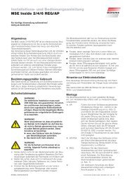
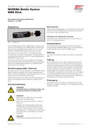
3.1 Operating elements<br />
<br />
<br />
<br />
Fig. 1<br />
The <strong>Wisotronic</strong> operating elements<br />
<br />
Display<br />
The illuminated display informs you on everything you can view and set on<br />
the <strong>Wisotronic</strong>. For example, you can view the current measured values of<br />
the outside brightness and outside temperature, the current time and much<br />
more. The various elements of the display are explained in detail in the Operating<br />
Instructions Art. No. 890557.<br />
2 Function buttons<br />
Depending on the information on the display, different processes can be<br />
triggered with the function buttons. For example, you may jump to the main<br />
menu, restore a preset value, cancel an input, and more.<br />
3 Touch wheel<br />
The touch wheel can be used to select and open menus, <strong>channel</strong>s, groups<br />
and scenes or current weather data and measuring values in the display.<br />
Simply move a finger along the circular depression (clockwise or anticlockwise).<br />
When you press the middle of the touch wheel, a preselected menu<br />
item opens, for example, or a modified value is accepted.<br />
12<br />
We reserve the right to carry out improvements<br />
890558_d•en•01.08.2013
Introduction<br />
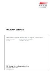
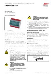
3.2 Principal structure of a<br />
<strong>Wisotronic</strong> system<br />
Weather station<br />
multisense<br />
<strong>Wisotronic</strong> 1-<strong>channel</strong><br />
230 V / 50 Hz<br />
Sunblind<br />
pushbutton<br />
Sun shading system<br />
Fig. 2<br />
Overview of the structure of a <strong>Wisotronic</strong> system<br />
The <strong>Wisotronic</strong> is a complete solution for controlling your sun shading product.<br />
Whatever the season, <strong>Wisotronic</strong> will lower your energy consumption and<br />
provide for a pleasant climate. The weather station multisense delivers all information<br />
necessary to respond properly to the weather to the <strong>Wisotronic</strong>.<br />
To make it possible for you to operate the sun shading product in the conventional<br />
manner, <strong>Wisotronic</strong> makes additional inputs available for connecting<br />
a conventional sunblind push button.<br />
890558_d•en•01.08.2013 We reserve the right to carry out improvements 13
Introduction<br />
<strong>Wisotronic</strong> 1-<strong>channel</strong><br />
<strong>Installation</strong> <strong>instructions</strong><br />
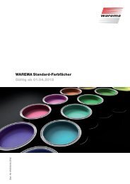
3.3 Concept<br />
Before you install and start the <strong>Wisotronic</strong>, this chapter will explain the basic<br />
concept of the system and familiarise you with the many options and the<br />
complex projects it can be used to realise.<br />
Product 1 (external venetian<br />
Channel 1 (external venetian<br />
Group 1 (<strong>channel</strong>s 1+2) Scene 1<br />
blind 1 south)<br />
blind 1 south)<br />
Product 2 (external venetian<br />
blind 2 east)<br />
Product 3 (roller shutter 3 west)<br />
Channel 2 (external venetian<br />
blind 2 east)<br />
Channel 3 (roller shutter 3 west)<br />
Group 2 (<strong>channel</strong> 3)<br />
.<br />
.<br />
Scene 2<br />
Scene 3<br />
Scene 4<br />
.<br />
.<br />
.<br />
.<br />
.<br />
.<br />
.<br />
Product 4 Channel 4 Group 4<br />
Products are considered to be<br />
all connected power consumers<br />
(e.g.: sun shading product,<br />
window).<br />
Products can be allocated to<br />
<strong>channel</strong>s (e.g.: <strong>channel</strong> 3, roller<br />
shutter west).<br />
Any number of <strong>channel</strong>s can<br />
be organised into groups (e.g.:<br />
group 1, all external venetian<br />
blinds).<br />
Any number of <strong>channel</strong>s can be<br />
organised into scenes; these<br />
<strong>channel</strong>s move to a position that<br />
is previously learned in for a set<br />
dwell time.<br />
Product settings<br />
Contact allocation<br />
Run times<br />
Slat angle<br />
Local pushbutton operating<br />
mode<br />
Channel settings:<br />
Product type<br />
Safety functions (wind, ice)<br />
Comfort functions ↵(precipitation,<br />
time, photo, dawn/dusk,<br />
temperature)<br />
A maximum of 4 groups can be<br />
created.<br />
There are no groups in the<br />
<strong>Wisotronic</strong> 1-<strong>channel</strong>.<br />
A maximum of 4 scenes can be<br />
created.<br />
Fig. 3<br />
Properties of products, <strong>channel</strong>s, groups and scenes<br />
14<br />
We reserve the right to carry out improvements<br />
890558_d•en•01.08.2013
Introduction<br />
3.3.1 Channels, facades and<br />
products<br />
NOTE<br />
Because misunderstandings have already occurred regarding the term<br />
"Facade" in the area of sun shading control systems, this point shall be explained<br />
here in more detail:<br />
The <strong>Wisotronic</strong> has 1, 2, 3 or 4 <strong>channel</strong>s, depending on the model. Each<br />
<strong>channel</strong> can access either a single product (e.g. an awning) or several products<br />
of the same type (e.g. roller shutters).<br />
To actuate multiple products through a single <strong>channel</strong> of the <strong>Wisotronic</strong>,<br />
additional components may be required (such as motor control units).<br />
➊ ➋ ➌<br />
Fig. 4<br />
Example: <strong>channel</strong>s of the <strong>Wisotronic</strong><br />
Example In the example illustrated above, <strong>channel</strong> 1 controls the awning on facade 1,<br />
<strong>channel</strong> 2 the conservatory awning on facade 2 and <strong>channel</strong> 3 the external<br />
venetian blinds of the conservatory on facade 2. This demonstrates that a<br />
distinction according to building facades cannot be made in this example<br />
since the individual <strong>channel</strong>s are of importance here.<br />
Example<br />
Another example: The <strong>Wisotronic</strong> controls all roller shutters on the west facade<br />
with <strong>channel</strong> 1, all roller shutters on the south facade with <strong>channel</strong> 2<br />
and all roller shutters on the east facade with <strong>channel</strong> 3. Because the control<br />
is divided here according to the facades, the term "facade" instead of "<strong>channel</strong>"<br />
could be used in this example.<br />
890558_d•en•01.08.2013 We reserve the right to carry out improvements 15
Introduction<br />
<strong>Wisotronic</strong> 1-<strong>channel</strong><br />
<strong>Installation</strong> <strong>instructions</strong><br />
NOTE<br />
In these <strong>instructions</strong> we only use the term "Channel".<br />
The <strong>Wisotronic</strong> always activates products through logic <strong>channel</strong>s. The following<br />
product types can presently be activated using the <strong>Wisotronic</strong>:<br />
Articulated arm awning<br />
Conservatory awning<br />
External venetian blind<br />
Roller shutters<br />
Pleated blind<br />
Venetian blind<br />
Window<br />
Inside roller blind<br />
Vertical awning<br />
Facade awning<br />
Drop-arm awning<br />
Markisolette<br />
Fault alarm contact<br />
3.3.2 Groups<br />
NOTE<br />
NOTE<br />
A product is connected directly to the outputs of a switch actuator of the<br />
<strong>Wisotronic</strong>. It requires one or two switching outputs; for example, sun shading<br />
products require two switching outputs for raising and lowering.<br />
If you want to drive several <strong>channel</strong>s together, they can be combined into a<br />
group. You can then, for example, raise or lower the conservatory awning<br />
and the external venetian blind of a conservatory together.<br />
The group “inherits” the product properties of the first assigned <strong>channel</strong>; if<br />
this is a roller shutter, for example, then the operating behaviour of the group<br />
corresponds to that of a roller shutter even if other slat products or windows<br />
belong to this group.<br />
Of course, <strong>channel</strong>s with identical products can also be combined to a<br />
group. For example, if you have created a <strong>channel</strong> for the roller shutters<br />
of each room, then all roller shutters of the building can be combined in a<br />
group and moved together.<br />
A maximum of 4 groups can be created.<br />
This function is not available for <strong>Wisotronic</strong> 1-<strong>channel</strong> since is does not have<br />
more than one <strong>channel</strong>.<br />
3.3.3 Scenes<br />
A scenario (e.g. “roller shutter DOWN, articulated arm awning UP, window<br />
CLOSED” when leaving the flat) can be stored (“learned”) in a scene and be<br />
called at a later time.<br />
For this, one or more <strong>channel</strong>s are associated with the scene and the positions<br />
and states are set as desired. After the scene is stored, this scenario<br />
can be recalled at any time by selecting the scene.<br />
A maximum of 4 scenes can be created.<br />
16<br />
We reserve the right to carry out improvements<br />
890558_d•en•01.08.2013
<strong>Installation</strong><br />
4 <strong>Installation</strong><br />
CAUTIO<br />
Dangerous situations and malfunctions are possible.<br />
The control and its auxiliary components may only be operated when<br />
installed and at the specified installation locations. Malfunctions of the<br />
system or dangerous situations may occur if this is neglected. In every<br />
case, this will render any guarantee or warranty null and void.<br />
4.1 Scope of delivery<br />
<br />
<br />
<br />
<br />
The <strong>Wisotronic</strong> package contains the following parts:<br />
Control panel<br />
Base plate with supply unit<br />
Flush-mounting box incl. 4 countersunk screws<br />
<strong>Wisotronic</strong> installation <strong>instructions</strong> (this document)<br />
<br />
<strong>Wisotronic</strong> operating <strong>instructions</strong> (art. no. 890557)<br />
<br />
Wiring diagrams (art. no. 816345)<br />
4.2 Options<br />
4.2.1 Weather station<br />
multisense<br />
4.2.2 Further options<br />
<br />
<br />
To operate the many different automatic controls, weather information<br />
needs to be collected. Suitable sensors are necessary. The weather station<br />
multisense was specifically developed for use with the <strong>Wisotronic</strong> – all<br />
important information is collected with a single device.<br />
If you purchased the <strong>Wisotronic</strong> without a weather station, it can be retrofitted<br />
with a weather station multisense.<br />
The <strong>Wisotronic</strong> can receive EWFS radio signals. With the optionally available<br />
WAREMA EWFS transmitters, you can remote control sun shading products<br />
connected to the <strong>Wisotronic</strong>.<br />
EWFS Hand-held transmitter 1-<strong>channel</strong> or EWFS Hand-held transmitter<br />
8-<strong>channel</strong><br />
EWFS Wall-mounted transmitter 1-<strong>channel</strong> or EWFS Wall-mounted transmitter<br />
8-<strong>channel</strong><br />
890558_d•en•01.08.2013 We reserve the right to carry out improvements 17
<strong>Installation</strong><br />
<strong>Wisotronic</strong> 1-<strong>channel</strong><br />
<strong>Installation</strong> <strong>instructions</strong><br />
CAUTIO<br />
When the equipment is delivered, a blue transport protection is mounted<br />
on the connector of the base plate. Leave it in place during the installation<br />
procedure to avoid bending the contacts. Remove the transport protection<br />
shortly before you mount the control panel.<br />
Fig. 5<br />
Base plate with transport protection<br />
18<br />
We reserve the right to carry out improvements<br />
890558_d•en•01.08.2013
<strong>Installation</strong><br />
4.3 Procedure<br />
Follow the points below in the order given:<br />
First determine where the individual components are to be installed. Refer to<br />
the specifications in this chapter and in the sensor data sheets.<br />
Do not use lines of a larger cross-section than specified.<br />
Then determine which cables are required to connect the components with<br />
one another. Use the <strong>instructions</strong> given in Chapter 5 on page 25.<br />
Lay the required lines. Preferably use cable ducts to route the motor lines.<br />
WARNIN<br />
Electrical operating equipment must be mounted for easy access<br />
(VDE0100).<br />
Install and wire the individual components.<br />
Check the wiring before switching on the power supply to the control.<br />
Then commission the unit. Only then will the control be ready to use. The<br />
steps required for commissioning are explained in detail in these <strong>instructions</strong>.<br />
Check the correct running direction of the sun shading product by operating<br />
the UP and DOWN buttons on the control.<br />
Check that the connected sensors are functioning properly.<br />
<br />
Check that the readings displayed in the Start menu for the temperature<br />
and brightness are plausible.<br />
<br />
Check that the wind speed reading changes when the vane is turned.<br />
<br />
Check whether precipitation is detected (moisten the sensor surface with<br />
water).<br />
Then adjust the functioning of the system to the ambient conditions and<br />
special requirements. Use the operating <strong>instructions</strong> as a guide as well.<br />
Chapter 10 ab Seite 83 of these <strong>instructions</strong> contains a table with all available<br />
setup steps (parameters), their limit values and the factory settings.<br />
If you change the factory settings, enter the new values of the unit into the<br />
table after completing the work.<br />
890558_d•en•01.08.2013 We reserve the right to carry out improvements 19
<strong>Installation</strong><br />
<strong>Wisotronic</strong> 1-<strong>channel</strong><br />
<strong>Installation</strong> <strong>instructions</strong><br />
4.4 Installing the control<br />
panel<br />
The <strong>Wisotronic</strong> 1-<strong>channel</strong> is designed for installation in a flush-mounting box<br />
(2); a surface-mounted housing () and a pattress box (3) are also available.<br />
The device is to be mounted in a dry and readily accessible location.<br />
57 20 7<br />
42 49<br />
2<br />
3<br />
Fig. 6<br />
Mounting options<br />
WARNIN<br />
The device is intended for operation in interiors only.<br />
<br />
<br />
<br />
Choose an installation height that permits convenient reading of the display<br />
(recommended: bottom edge of the device approx. 1.45 m above the top<br />
surface of the flooring).<br />
A temperature sensor is integrated in the control panel itself. Therefore, to<br />
prevent erroneous readings, do not install the control panel where a heat<br />
source may influence the measurements (sunlight, radiator, outside wall).<br />
The control panel is equipped with an EWFS radio receiver. The range of<br />
radio controls is restricted by legal regulations for radio systems and through<br />
structural factors. Adequate radio reception must be ensured when planning<br />
the project. This applies especially if transmitter and receiver are in different<br />
locations and the radio signal must pass through walls and ceilings. The<br />
control unit should not be installed in the immediate vicinity of metal surfaces<br />
(steel beam, fire door).<br />
Therefore, check that the receiver is functioning properly before the final installation.<br />
NOTE<br />
Strong local transmitter system (e.g. baby monitors or adjacent senders) with<br />
transmission frequencies identical to that of the control system can interfere<br />
with the reception.<br />
20<br />
We reserve the right to carry out improvements<br />
890558_d•en•01.08.2013
<strong>Installation</strong><br />
4.4.1 Flush-mounting<br />
When the <strong>Wisotronic</strong> base plate is mounted on a flush-mounting box, the<br />
control panel protrudes approx. 21 mm from the mounting surface.<br />
<br />
2<br />
3<br />
<br />
Fig. 7<br />
Base plate<br />
<strong>Installation</strong> in flush-mounting box<br />
2 Supply unit<br />
3 Flush-mounted box<br />
NOTE<br />
After the lines are connected, the unit is attached with the included countersunk<br />
screws.<br />
Do not tighten the screws too tightly as this might damage the base plate.<br />
Ensure that none of the connecting lines are pinched during installation.<br />
After installation in the flush-mounting box, the base plate of the supply unit<br />
must be flush with the wall; otherwise, the control panel may not engage<br />
correctly. The flush-mounting box should therefore be mounted in a vertical<br />
position.<br />
890558_d•en•01.08.2013 We reserve the right to carry out improvements 21
<strong>Installation</strong><br />
<strong>Wisotronic</strong> 1-<strong>channel</strong><br />
<strong>Installation</strong> <strong>instructions</strong><br />
4.4.2 Suface-mounting<br />
If required by the installation situation, <strong>Wisotronic</strong> can be surface-mounted.<br />
A surface-mounting housing is available in black or white.<br />
<br />
2<br />
3<br />
Fig. 8<br />
<strong>Installation</strong> in surface-mounted housing<br />
<br />
Base plate<br />
2 Supply unit<br />
3 Surface-mounted housing<br />
NOTE<br />
After the lines are connected, the unit is attached with the included countersunk<br />
screws.<br />
Do not tighten the screws too tightly as this might damage the base plate.<br />
Ensure that none of the connecting lines are pinched during installation.<br />
22<br />
We reserve the right to carry out improvements<br />
890558_d•en•01.08.2013
<strong>Installation</strong><br />
4.4.3 Mounting in pattress box<br />
A special pattress box (art. no. 1002 837) is available as an alternative.<br />
The <strong>Wisotronic</strong> can be mounted nearly flush with the wall in the pattress box;<br />
the control panel protrudes approx. 7 mm above the installation surface.<br />
<br />
2<br />
3<br />
Fig. 9<br />
<strong>Installation</strong> in surface-mounted housing<br />
NOTE<br />
After the lines are connected, the unit is attached with the included countersunk<br />
screws.<br />
Do not tighten the screws too tightly as this might damage the base plate.<br />
Ensure that none of the connecting lines are pinched during installation.<br />
890558_d•en•01.08.2013 We reserve the right to carry out improvements 23
<strong>Installation</strong><br />
<strong>Wisotronic</strong> 1-<strong>channel</strong><br />
<strong>Installation</strong> <strong>instructions</strong><br />
4.4.4 Attach control panel<br />
CAUTIO<br />
Always switch off the operating voltage before mounting or removing the<br />
control panel. Connecting or disconnecting the plug-in connections during<br />
operation can damage the device.<br />
<br />
Take off the blue transport protection from the base plate.<br />
Mount the control panel straight on the base plate. Make sure not to wedge<br />
the control panel; otherwise, the plug-in connection between the control panel<br />
and the base plate may be damaged or short circuits could result.<br />
The control panel is now securely mounted to the wall.<br />
Familiarise yourself with the <strong>Wisotronic</strong> and the commissioning procedure<br />
before proceeding. The necessary information can be found in<br />
Chapter 6 ab Seite 32.<br />
Commission the <strong>Wisotronic</strong> as described in Chapter 7 on page 36.<br />
24<br />
We reserve the right to carry out improvements<br />
890558_d•en•01.08.2013
Connection<br />
5 Connection<br />
Adhere to all of the following information when connecting the <strong>Wisotronic</strong>.<br />
Only connect the <strong>Wisotronic</strong> and the associated components as described.<br />
5.1 Connection<br />
information<br />
WARNIN<br />
The electrical installation must be performed by a certified electrician in<br />
accordance with the electrical installation regulations published by the<br />
Association of German Electrical Engineers (VDE 0100) or the standards<br />
and regulations of the country in which the device is being installed.<br />
WARNIN<br />
In a permanently routed installation, there must be an in-series<br />
disconnecting and isolating device to separate the <strong>Wisotronic</strong> from<br />
the supply voltage (switch according to EN 60335-1, Section 25.2, e.g.<br />
circuit breaker). The associated motor control unit (MSE) and its power<br />
consumers should not be protected by this circuit breaker.<br />
<br />
<br />
<br />
<br />
<br />
DANGE<br />
The components must be disconnected from the mains voltage before the<br />
enclosure is opened.<br />
When establishing the supply line connection, apply EN 60335-1 (line<br />
cross-section, line type, additional locks to prevent loosening, strain relief,<br />
wire ferrules for wire conductors, circuit breakers).<br />
The operator or installer is responsible for compliance with the public utility<br />
provider regulations and the VDE regulations according to VDE 0022.<br />
The wiring specified in the cable diagrams is for minimum cross sections<br />
in copper, taking no account of the length and the resulting voltage drops.<br />
The relevant VDE regulations must be followed when routing lines outdoors.<br />
Furthermore, the lines must be suitable for outdoor use. The distance<br />
to high-voltage power lines must be at least 20 cm; parallel routing<br />
to lines carrying mains voltage must be avoided. The insulation voltage<br />
between shielding and wires must be > 2.5 kV. The lines should be routed<br />
in one piece.<br />
A screw driver size 0 is needed to tighten the terminals. Electric screw<br />
drivers may not be used.<br />
890558_d•en•01.08.2013 We reserve the right to carry out improvements 25
Connection<br />
<strong>Wisotronic</strong> 1-<strong>channel</strong><br />
<strong>Installation</strong> <strong>instructions</strong><br />
NOTE<br />
Common low-voltage cables (e.g. JY(St)Y) are normally used for switch, sensor<br />
and network lines. This is usually sufficient regarding EMC interferences,<br />
e.g. in residential rooms at line lengths up to 50 m. By contrast, optimal protection<br />
against EMC interference is provided by high-quality lines with braided<br />
shields (no foil shields) and tightly twisted cable pairs. The longer the line,<br />
the greater the susceptibility toward interference. For this reason, only install<br />
high-quality cables.<br />
DANGE<br />
If the sun shading products are lowered for maintenance, repair, cleaning<br />
or similar, the entire sun shading product must subsequently be taken out<br />
of operation using an in-series disconnecting and isolation switch.<br />
CAUTIO<br />
The external 24 V voltage supplied by the <strong>Wisotronic</strong> are intended for<br />
WAREMA sensors only. The connection of other components can result in<br />
malfunctions, failures or device damage.<br />
5.2 Terminals<br />
The <strong>Wisotronic</strong> is equipped with standardised spring terminals designed for<br />
quick and secure connections.<br />
<br />
<br />
<br />
<br />
<br />
Fig. 10<br />
Spring terminals<br />
After the wire is stripped, it is pressed into the terminal 1 until the insulation<br />
on the wire enters the terminal and the conductor is securely held in the terminal<br />
2. To release the connection, the release key is pushed in all the way<br />
with a screw driver and the conductor is pulled out of the terminal 3.<br />
26<br />
We reserve the right to carry out improvements<br />
890558_d•en•01.08.2013
Connection<br />
5.3 Wiring diagrams<br />
The following connections are found on the back of the <strong>Wisotronic</strong>:<br />
Terminal block X1<br />
Connection of supply line<br />
230 V AC<br />
Terminal block X2<br />
Floating output for connecting<br />
a floor distribution<br />
control unit, for actuating<br />
motor control units or for<br />
connecting a motor<br />
3,15 AT<br />
Fuse<br />
(for terminals X2, accessible<br />
from device side).<br />
Note: There are no parts<br />
within the device that require<br />
maintenance. In case of a<br />
malfunction, the installed<br />
fuse may only be replaced<br />
by qualified electrical<br />
personnel.<br />
Terminal block X3<br />
Connection of sensors<br />
(terminals 1 to 4) and the<br />
local operating elements<br />
(terminals 5 to 7)<br />
Fig. 11<br />
<strong>Wisotronic</strong> 1-<strong>channel</strong> connections<br />
WARNIN<br />
Insert the lines for the drive and power supply into the junction box from<br />
above and insert the lines for the sensors from below.<br />
Lines that carry current must be at least 8 mm away from sensor lines.<br />
If 24 V control lines are connected to terminal block X2, the lines must be<br />
routed at least 8 mm away from the 230 V lines. Otherwise, the 24 V lines<br />
must be doubly insulated (e.g. with silicone hoses).<br />
890558_d•en•01.08.2013 We reserve the right to carry out improvements 27
Connection<br />
<strong>Wisotronic</strong> 1-<strong>channel</strong><br />
<strong>Installation</strong> <strong>instructions</strong><br />
5.3.1 Power supply and control<br />
lines<br />
If you wish to activate several sun shading products with the <strong>Wisotronic</strong>, you<br />
can connect a floor distribution control or motor control units to terminals X2<br />
instead of a sun shading drive.<br />
C<br />
E<br />
To the floor distribution controls<br />
or to the motor control units.<br />
See the wiring diagrams<br />
document, art. no. 816 345<br />
Supply line<br />
100-240 V AC<br />
50/60Hz / 16 A<br />
NYM-J 3x1,5<br />
3,15 AT<br />
Fig. 12<br />
Connection of the power supply and control lines<br />
Terminal blocks X1, X2<br />
Permissible line cross section<br />
Stripping length<br />
0.2 to 1.5 mm 2 single-wire<br />
10 mm<br />
WARNIN<br />
In a permanently routed installation, there must be an in-series<br />
disconnecting and isolating device to separate the <strong>Wisotronic</strong> from<br />
the supply voltage (switch according to EN 60335-1, Section 25.2, e.g.<br />
circuit breaker). The associated motor control unit (MSE) and its power<br />
consumers should not be protected by this circuit breaker.<br />
If 24 V control lines are connected to terminal block X2, the lines must be<br />
routed at least 8 mm away from the 230 V lines. Otherwise, the 24 V lines<br />
must be doubly insulated (e.g. with silicone hoses).<br />
28<br />
We reserve the right to carry out improvements<br />
890558_d•en•01.08.2013
Connection<br />
5.3.2 Sun shading drive<br />
If you wish to activate several sun shading products with the <strong>Wisotronic</strong>, you<br />
can connect a floor distribution control or motor control units to terminals X2<br />
instead of a sun shading drive.<br />
Motor 1<br />
1<br />
M1~<br />
3<br />
2<br />
Terminal<br />
(included)<br />
H05RR-F 4 G 0.75 BK<br />
1<br />
1<br />
GNYE<br />
BU<br />
BN<br />
3<br />
3<br />
BK<br />
2 Plug-and-socket connection<br />
2<br />
Only one drive may be<br />
connected per <strong>channel</strong>.<br />
Parallel connection of<br />
multiple drives will<br />
damage the motor.<br />
Supply line<br />
100-240 V AC<br />
50/60 Hz / 16 A<br />
NYM-J 3x1,5<br />
PE<br />
L<br />
N<br />
3,15 AT<br />
Fig. 13<br />
Connection of a sun shading drive<br />
Terminal blocks X1, X2<br />
Permissible line cross section<br />
Stripping length<br />
0.2 to 1.5 mm 2 single-wire<br />
10 mm<br />
WARNIN<br />
In a permanently routed installation, there must be an in-series<br />
disconnecting and isolating device to separate the <strong>Wisotronic</strong> from<br />
the supply voltage (switch according to EN 60335-1, Section 25.2, e.g.<br />
circuit breaker). The associated motor control unit (MSE) and its power<br />
consumers should not be protected by this circuit breaker.<br />
890558_d•en•01.08.2013 We reserve the right to carry out improvements 29
Connection<br />
<strong>Wisotronic</strong> 1-<strong>channel</strong><br />
<strong>Installation</strong> <strong>instructions</strong><br />
5.3.3 Sensor<br />
The weather station multisense delivers all of the weather data needed to<br />
efficiently utilise the wide range of automatic functions of the <strong>Wisotronic</strong>. It<br />
simply needs to be connected with a 4-wire line.<br />
Weather station multisense<br />
View from below<br />
Terminal 1: 0 V<br />
Terminal 2: 24 V<br />
Terminal 3: A<br />
Terminal 4: B<br />
OG<br />
1 2 3 4<br />
BN<br />
BK<br />
RD<br />
Strain relief<br />
4 x AWG 26 UL black<br />
RD RD<br />
BK BK<br />
BN<br />
YE<br />
OG<br />
WH<br />
Onsite<br />
junction<br />
box<br />
RD<br />
BK<br />
YE<br />
WH<br />
JY(St)Y 2 x 2 x 0.8mm<br />
Fig. 14<br />
Weather station multisense connection<br />
Terminal block X3 (terminals 1 to 4)<br />
Permissible line cross section<br />
Stripping length<br />
Maximum line length<br />
0.12 to 0.5 mm 2 single-wire<br />
6.5 mm<br />
200 m<br />
Only use lines of type JY(St)Y 2x2x0.8 mm.<br />
The <strong>Wisotronic</strong> automatically detects whether sensors are connected and<br />
which ones.<br />
CAUTIO<br />
If no sensors are connected, only the current room temperature is<br />
displayed and nothing can be damaged on the control. However, please<br />
be aware that in this case, the sun shading control system cannot function<br />
correctly and that this may result in damage to your sun shading system.<br />
NOTE<br />
Depending on the mounting situation, you can also directly route the line of<br />
type JY(St)Y to the weather station multisense. It must be ensured that the<br />
line is protected against UV radiation (e.g. in a conduit, hose) along its entire<br />
length. Mount the line in such a way that water cannot penetrate the device<br />
or enter into the building.<br />
30<br />
We reserve the right to carry out improvements<br />
890558_d•en•01.08.2013
Connection<br />
5.3.4 Local push buttons<br />
Local push button inputs are available for the local operation of connected<br />
sun shading products. A conventional sunblind push button can be connected.<br />
JY (St) Y 2x2x0.8 mm ø<br />
max. 200 m<br />
0<br />
P<br />
2 1<br />
Fig. 15<br />
Connection of local push buttons<br />
Terminal block X3 (terminals 5 to 7)<br />
Permissible line cross section<br />
Stripping length<br />
Maximum line length<br />
0.12 to 0.5 mm 2 single-wire<br />
6.5 mm<br />
200 m<br />
890558_d•en•01.08.2013 We reserve the right to carry out improvements 31
Overview<br />
<strong>Wisotronic</strong> 1-<strong>channel</strong><br />
<strong>Installation</strong> <strong>instructions</strong><br />
6 Overview<br />
First menu level<br />
Second menu level<br />
Third menu level<br />
...<br />
In these <strong>instructions</strong>, miniature menu structures are presented at all important<br />
locations (see the example here). They will help you navigate to the functions<br />
described there without having to leaf through an excessive number of<br />
menus.<br />
6.1 Start menu<br />
When the supply voltage of the <strong>Wisotronic</strong> has been switched on and you<br />
have selected English as language, then you are automatically in the main<br />
menu.<br />
The following figure shows the <strong>Wisotronic</strong> start menu:<br />
<br />
<br />
<br />
<br />
<br />
<br />
<br />
Fig. 16<br />
<strong>Wisotronic</strong> start menu<br />
A<br />
B<br />
C<br />
D<br />
E<br />
F<br />
G<br />
The start menu elements:<br />
Display of date and time<br />
The header is fully visible in all menu levels.<br />
Status display<br />
These symbols are only displayed when a status is active.<br />
Display of the menu name<br />
Display of the current weather data<br />
Indicator of whether the control functions are active<br />
Indicator of whether "Absent" is active<br />
Display of the button functions in the current menu<br />
The footer is fully visible in all menu levels.<br />
32<br />
We reserve the right to carry out improvements<br />
890558_d•en•01.08.2013
Overview<br />
The header is visible in all menu levels. The date and time are shown at the<br />
top (A). Various symbols are shown between the date and time, depending<br />
on the state of the <strong>Wisotronic</strong> (B, Chapter 6.1.1). Below this, the menu in<br />
which you are currently located (C) is identified.<br />
The currently measured weather data of the sensors (D) appear in the<br />
display field below this. In addition, you will see whether you have activated<br />
the Automatic features (E) and whether the "Absent" switch has been<br />
pushed on the control panel (F).<br />
The footer (G) always shows which functions the four buttons below it currently<br />
have.<br />
The following functions are assigned to the buttons in the start menu:<br />
The [Main] function button leads to the main menu, where you can access<br />
scenes, <strong>channel</strong>s and groups. With the [Auto] button, you can switch the<br />
automatic modes of the <strong>Wisotronic</strong> on and off. The [Absent] button is used<br />
to activate the Absent function. The [Meas. val.] function button takes you<br />
back to the start menu, where the measurement values, causes, malfunctions<br />
and histories are displayed. Histories are graphic presentations of the<br />
chronological sequences of measured values that can be conveniently traced<br />
with the cursor.<br />
6.1.1 Status display<br />
The symbols in the header indicate the following states of the <strong>Wisotronic</strong>:<br />
Data must be loaded into the devices<br />
Service mode<br />
A fault occurred. Fault messages are displayed in the fault menu<br />
([Start menu] > [Measured values] > [Faults]).<br />
"Leave" function is activate<br />
"Absent" function is active<br />
890558_d•en•01.08.2013 We reserve the right to carry out improvements 33
Overview<br />
<strong>Wisotronic</strong> 1-<strong>channel</strong><br />
<strong>Installation</strong> <strong>instructions</strong><br />
The following figure shows the <strong>Wisotronic</strong> Start menu with its elements in the<br />
service mode:<br />
Fig. 17<br />
Start menu of the <strong>Wisotronic</strong> (in the service mode)<br />
For specialist dealers:<br />
To access the service mode:<br />
Change to the main menu using the [Main menu] button.<br />
In the main menu, press the [Sett.] button and, in the [Settings] menu, select<br />
the [Service] line.<br />
Press the touch wheel; switch to numeric input by pressing the [A/a/1] button<br />
twice and by entering the password [5858] in the [Service] menu.<br />
34<br />
We reserve the right to carry out improvements<br />
890558_d•en•01.08.2013
Overview<br />
6.2 Typical approaches for<br />
commissioning<br />
NOTE<br />
The <strong>Wisotronic</strong> allows for different approaches to commissioning. Depending<br />
on the complexity of the building project, commissioning may take place via:<br />
<br />
The Quickstart on the control panel<br />
It guides you to a finished project with the basic settings in just a few steps.<br />
During the setup procedure, the most important parameters can be viewed<br />
and changed. In a final step, they are transferred to the connected devices<br />
(sensors and actuators).<br />
<br />
Manual commissioning<br />
For complex building projects with special requirements and settings, it may<br />
be useful to perform a manual commissioning.<br />
Proceed in this sequence:<br />
Create <strong>channel</strong>s, create product, load data into the devices, set the parameters<br />
for the comfort and safety functions.<br />
You can also use the Quickstart to create the basic framework of your project<br />
and then continue by manually adjusting the system to your preferences and<br />
circumstances.<br />
After the project data have been stored in <strong>Wisotronic</strong>, they are uploaded to<br />
the actuators.<br />
The system is now ready for operation.<br />
890558_d•en•01.08.2013 We reserve the right to carry out improvements 35
Commissioning<br />
<strong>Wisotronic</strong> 1-<strong>channel</strong><br />
<strong>Installation</strong> <strong>instructions</strong><br />
7 Commissioning<br />
CAUTIO<br />
Before the unit can be commissioned, all components must be connected.<br />
The <strong>Wisotronic</strong> automatically detects whether sensors are connected and<br />
which ones. The <strong>Wisotronic</strong> cannot optimally control the sun shading product<br />
and display measuring values until all required sensors are connected.<br />
Refer to the associated operating <strong>instructions</strong> prior to commissioning to optimally<br />
adapt the control to your requirements. There you will find a complete<br />
overview of the <strong>Wisotronic</strong> functions.<br />
In the individual menus of the manual project setup<br />
(see Chapter 8 on page 43), the experienced user can set each parameter<br />
individually.<br />
7.1 Planning with<br />
Quickstart<br />
Quickstart offers support to the specialist dealer with the creation of a project,<br />
making it easy to make the basic settings. It always begins with a new,<br />
empty project.<br />
<br />
Switch on the mains supply.<br />
The WAREMA log appears during the start procedure. The Quickstart menu<br />
appears as soon as the <strong>Wisotronic</strong> is operational.<br />
In just a few steps, you can commission the device with the most important<br />
basic parameters.<br />
NOTE<br />
The <strong>Wisotronic</strong> automatically detects the connected components when the<br />
operating voltage is switched on (e.g. the weather station).<br />
36<br />
We reserve the right to carry out improvements<br />
890558_d•en•01.08.2013
Commissioning<br />
7.1.1 Language<br />
<br />
First set the operating language of the <strong>Wisotronic</strong>. If the desired language is<br />
already set, continue with the entry of the date and time.<br />
Press the touch wheel to change the language.<br />
The current language changes colour:<br />
At the time of printing of these <strong>instructions</strong>, the following languages were implemented<br />
as operating languages.<br />
<br />
German<br />
<br />
English<br />
<br />
French<br />
<br />
Spanish<br />
<br />
Italian<br />
<br />
Norwegian<br />
To set the operating language, toggle between the available languages by<br />
turning the touch wheel.<br />
Press the touch wheel to confirm your selection.<br />
NOTE<br />
When the power supply returns after an interruption, the Start menu appears<br />
in the display in the language last selected.<br />
890558_d•en•01.08.2013 We reserve the right to carry out improvements 37
Commissioning<br />
<strong>Wisotronic</strong> 1-<strong>channel</strong><br />
<strong>Installation</strong> <strong>instructions</strong><br />
7.1.2 Time<br />
<br />
Set the current time in 24-hour format:<br />
Select the [Time] line and press the touch wheel.<br />
The hours display changes colour:<br />
Turn the touch wheel to set the hours of the "Time hh:mm" value. Pressing on<br />
the wheel causes the display to jump to minutes. Set the minutes in the same<br />
manner.<br />
Accept the value by pressing the touch wheel.<br />
The function button [Stand.] sets the hours to 12, the minutes to 30 (factory<br />
setting).<br />
Pressing the [Cancel] function button returns you to the menu without making<br />
changes.<br />
38<br />
We reserve the right to carry out improvements<br />
890558_d•en•01.08.2013
Commissioning<br />
7.1.3 Date<br />
<br />
Set the date and time functions in this menu:<br />
Select the [Date] line.<br />
The following view appears in the display:<br />
<br />
NOTE<br />
Now select the [Day] line by turning the touch wheel and enter the current<br />
day. Proceed in the same manner with month and year.<br />
The weekday is automatically calculated from the entered date.<br />
After you have selected the [Standard time/daylight sav.] menu line,<br />
one rotation increment of the touch wheel to the left sets the standard time;<br />
one rotation increment to the right sets the daylight saving time.<br />
The [Standard time/daylight auto] and [Use DCF77] functions can be activated<br />
or deactivated by setting or deleting the checkmark.<br />
The DCF-77 time signal is only available if you are using a suitable sensor.<br />
This function is not available at this time. Ensure that the "Use DCF77" function<br />
is deactivated.<br />
<br />
The settings for the date and time functions have now been set.<br />
Pressing the [Back] function button returns you to the [Quickstart] menu.<br />
890558_d•en•01.08.2013 We reserve the right to carry out improvements 39
Commissioning<br />
<strong>Wisotronic</strong> 1-<strong>channel</strong><br />
<strong>Installation</strong> <strong>instructions</strong><br />
7.1.4 Channel 1 <strong>channel</strong> type<br />
NOTE<br />
In the next step, select the <strong>channel</strong> type that fits to the connected product.<br />
An overview of the selected product types and the associated parameters can<br />
be found in Chapters 10.2 on page 90 and 10.3 on page 91.<br />
<br />
Select the [Channel 1 Channel type] line and press the touch wheel.<br />
The right display changes colour:<br />
<br />
Turn the touch wheel until the desired product is displayed.<br />
Accept the value by pressing the touch wheel.<br />
The basic settings for the selected product (for an external venetian blind in<br />
this example) and all applicable automatic parameters are set automatically.<br />
Adjust the settings for [Run time mm:ss] and [Allocation photosensor] if you<br />
require different settings.<br />
40<br />
We reserve the right to carry out improvements<br />
890558_d•en•01.08.2013
Commissioning<br />
7.1.5 Load data into the<br />
actuator<br />
<br />
For the <strong>Wisotronic</strong> to function correctly, the settings need to be loaded into<br />
the actuator.<br />
Press the [Finished] button after you have made all of the settings in the<br />
Quickstart menu.<br />
The following menu is displayed:<br />
<br />
[Please wait...] appears first, followed by the message<br />
[Writing_to_Actuator].<br />
The main menu appears after all data are loaded.<br />
The <strong>Wisotronic</strong> is ready for operation.<br />
890558_d•en•01.08.2013 We reserve the right to carry out improvements 41
System settings<br />
<strong>Wisotronic</strong> 1-<strong>channel</strong><br />
<strong>Installation</strong> <strong>instructions</strong><br />
7.1.6 Factory reset<br />
If you would like to make changes or correct mistakes in the Quickstart menu<br />
after closing it with the [Finished] button, you can return to the beginning of<br />
the Quickstart menu using the factory reset.<br />
<br />
<br />
De-energize the device.<br />
Switch the operating voltage back on.<br />
Wait for the WAREMA logo to appear during the start routine.<br />
Immediately hold down all four buttons on the <strong>Wisotronic</strong> briefly.<br />
The following menu appears with the question<br />
[Reset to factory defaults]:<br />
<br />
With the [Yes/No] button, confirm that you wish to reset the device to the factory<br />
settings.<br />
The WAREMA logo appears again as well as the<br />
[>> setting factory defaults] screen. The display returns to the Quickstart<br />
menu after approx. 30 s.<br />
The <strong>Wisotronic</strong> has now been reset to the factory settings and is ready for<br />
reconfiguration. Follow the Quickstart menu as described in Chap. 7.1 on<br />
page 36 ff<br />
42<br />
We reserve the right to carry out improvements<br />
890558_d•en•01.08.2013
System settings<br />
8 Manual<br />
commissioning<br />
8.1 Creating system<br />
settings<br />
Press the [Sett.] button and select the [Service] menu in the [Settings]<br />
window.<br />
Press the touch wheel and enter the password [5858] (or your own selected<br />
password).<br />
Press the touch wheel and select the [Project setup] menu.<br />
Various system settings can be performed in the [System] menu of the project<br />
setup:<br />
8.1.1 Date and time<br />
Main menu<br />
Settings<br />
Service<br />
Project setup<br />
System<br />
Date/time<br />
All date and time parameters can be entered in this window:<br />
The operating step sequence is the same in each case:<br />
Select the desired parameter by turning the touch wheel.<br />
Start editing by pressing the touch wheel (parameter value changes colour).<br />
Turning the touch wheel changes the value; pressing it changes the decimal<br />
place or closes the entry (the coloured highlighting disappears).<br />
Press the [Back] button to return to the [System] menu.<br />
890558_d•en•01.08.2013 We reserve the right to carry out improvements 43
System settings<br />
<strong>Wisotronic</strong> 1-<strong>channel</strong><br />
<strong>Installation</strong> <strong>instructions</strong><br />
8.1.2 Display settings<br />
Main menu<br />
Settings<br />
Service<br />
Project setup<br />
System<br />
Display<br />
Select [Brightness at standby] by pressing the touch wheel; turning the wheel<br />
changes the value between 10% and 100%. If you select a setting below<br />
10% (OFF is displayed), the display will go completely dark later on when<br />
standby is active. You can return to the default value at any time by using the<br />
[Stand.] button.<br />
Set the [Brightness at operation] in the same manner in the next menu line.<br />
Button tone: The button tone of the four sensor buttons (a soft click) can be<br />
activated and deactivated here.<br />
Duration of standby mode: The time can be set in the range of 1 to 240 min.<br />
With [Colour scheme], you can change the colours of the display. Two colour<br />
schemes are available: "dark" and "light".<br />
Press the [Back] button to return to the [System] menu.<br />
44<br />
We reserve the right to carry out improvements<br />
890558_d•en•01.08.2013
System settings<br />
8.1.2.1 Display behaviour of<br />
<strong>Wisotronic</strong><br />
[Brightness at operation]<br />
(10...100%)<br />
[Brightness at standby]<br />
(OFF, 10...100%)<br />
[Standby mode]<br />
[Standby duration]<br />
(1...240 min)<br />
—<br />
0 3 15 16...255 Minutes<br />
Last operating procedure<br />
Dim to standby<br />
brightness<br />
Change to standby<br />
mode, display Start<br />
menu<br />
Activate screen saver,<br />
display time<br />
Fig. 18<br />
Display behaviour<br />
890558_d•en•01.08.2013 We reserve the right to carry out improvements 45
System settings<br />
<strong>Wisotronic</strong> 1-<strong>channel</strong><br />
<strong>Installation</strong> <strong>instructions</strong><br />
8.1.3 Measured values start<br />
menu<br />
Start menu<br />
Main menu<br />
Settings<br />
System<br />
Measured values start menu<br />
NOTE<br />
In this menu you can define which measured values are displayed in the<br />
Start menu. You can select which sensors are to be evaluated.<br />
The measured values of the weather station multisense are always displayed<br />
in the Start menu. If you have not installed any other sensors, you can skip<br />
this step.<br />
This menu is also available to the user. It therefore can only be reached via<br />
the openly accessible [System] menu.<br />
<br />
Press the [Sett.] function button in the main menu and then go to the<br />
[System] > [Measured values start menu].<br />
The following menu is displayed:<br />
Here you can assign the desired sensors to the four measured values that<br />
appears in the Start menu. For each measured value, only the sensors that<br />
are actually available are offered for selection.<br />
Using the touch wheel, select a measured value and assign a sensor from<br />
the displayed selection.<br />
The [Delete] function button removes the currently assigned sensor and<br />
[---] is displayed. This measured value no longer appears in the Start menu.<br />
The [Stand.] function button resets the selection to the default assignment.<br />
The [Canc.] function button is used to leave the selection menu without making<br />
a change.<br />
Press the [Back] button to return to the [System] menu.<br />
46<br />
We reserve the right to carry out improvements<br />
890558_d•en•01.08.2013
System settings<br />
8.1.4 Select language<br />
Main menu<br />
Settings<br />
Service<br />
Project setup<br />
System<br />
Language<br />
The operating language is selected in this window.<br />
At the time of printing of these <strong>instructions</strong>, the following languages were implemented<br />
as operating languages.<br />
<br />
German<br />
<br />
English<br />
<br />
French<br />
<br />
Spanish<br />
<br />
Italian<br />
<br />
Norwegian<br />
Press the [Back] button to return to the [System] menu.<br />
NOTE<br />
The set language is retained even if there is an interruption in the power supply.<br />
The default language when the unit is first commissioned is German.<br />
890558_d•en•01.08.2013 We reserve the right to carry out improvements 47
System settings<br />
<strong>Wisotronic</strong> 1-<strong>channel</strong><br />
<strong>Installation</strong> <strong>instructions</strong><br />
8.1.5 Sensor compensation<br />
Main menu<br />
Settings<br />
Service<br />
Project setup<br />
System<br />
Sensor compensation<br />
<br />
This menu serves to calibrate the internal and external sensors of your <strong>Wisotronic</strong><br />
to the temperatures measured on site. This may become necessary if<br />
a sensor was mounted in an unfavourable location (such as in the vicinity of<br />
a heat source or in direct sunlight).<br />
Open the following menu: [Project setup] > [System] ><br />
[Sensor compensation].<br />
The following menu appears where the max. possible number of sensors for<br />
temperature is indicated:<br />
8.1.5.1 Control panel temperature<br />
8.1.5.2 Weather station 1 (2,3)<br />
outside temperature<br />
NOTE<br />
The [Control panel temperature] value specifies by how many degrees<br />
Celsius the measured value of the internal sensor of the <strong>Wisotronic</strong> is corrected<br />
up or down. The setting range is –10 °C to +10 °C.<br />
Turn the touch wheel to set the value [Control panel temperature].<br />
The [Stand.] function button sets the value to the factory setting.<br />
The [Multisense 1 Outside temperature] value specifies by how many<br />
degrees Celsius the measured value of weather station 1 is corrected up or<br />
down. The setting range is –30...+10 °C.<br />
Turn the touch wheel to set the value [Multisense 1 Outside temp.].<br />
The [Stand.] function button sets the value to the factory setting.<br />
Weather stations 2 and 3 are not available for <strong>Wisotronic</strong> 1-<strong>channel</strong>.<br />
NOTE<br />
When commissioning, note that the weather station multisense has an internal<br />
temperature correction feature that improves measurement accuracy. The<br />
device follows temperature changes at a rate of approx. 10 min per °C.<br />
When the <strong>Wisotronic</strong> is first switched on, the first temperature measurement<br />
is taken at the weather station multisense. If the weather station was previously<br />
stored at a considerably lower or higher temperature, it may take several<br />
hours before the correct temperature is displayed.<br />
If the weather station is already at the temperature of its environment when<br />
the <strong>Wisotronic</strong> is first switched on, the actual temperature measurement<br />
value will be displayed from the start.<br />
48<br />
We reserve the right to carry out improvements<br />
890558_d•en•01.08.2013
System settings<br />
8.1.6 Wind test<br />
Main menu<br />
Settings<br />
Service<br />
Project setup<br />
System<br />
Wind test<br />
In this menu, a wind test can be set to monitor the sensors and an alarm, if<br />
one occurs, can be reset (after resolving a defect or wire break).<br />
NOTE<br />
As a typical value for the duration of the wind test, we recommend 99 hours.<br />
The [Wind test alarm] line is for display only. If an alarm is triggered, the<br />
name of the weather station that triggered the alarm appears at the left.<br />
NOTE<br />
The menu lines below this line list the connectable wind sensors.<br />
Activate all components for which a wind test should be performed.<br />
If you accidentally activate the wind test for a sensor that is not connected,<br />
an alarm is always issued after the set duration elapses.<br />
Press the [Back] button to return to the [System] menu.<br />
890558_d•en•01.08.2013 We reserve the right to carry out improvements 49
System settings<br />
<strong>Wisotronic</strong> 1-<strong>channel</strong><br />
<strong>Installation</strong> <strong>instructions</strong><br />
8.1.7 Service access<br />
Main menu<br />
Settings<br />
Service<br />
Project setup<br />
System<br />
Service access<br />
The service password can be changed in this menu. It can have from 1 to 8<br />
characters.<br />
The preset password is [5858]. This value can be changed to ensure that access<br />
to the project setup and safety functions is exclusively available to the<br />
specialist dealer.<br />
My password:<br />
To change the service password:<br />
Press the [A/a/1] button, if desired, to switch between upper and lower case<br />
or numbers and special characters.<br />
The Turn the touch wheel to select a character from the selection field (bottom)<br />
(if you change the password, please note it down in the field on the<br />
left).<br />
Press the touch wheel to enter the selected symbol in the input field (top).<br />
If the characters are to be deleted, press the [ ] button once or twice or<br />
keep it depressed.<br />
<br />
Press the [Back] button to return to the [System] menu.<br />
The new password is saved at the same time.<br />
Press the [Back] button once more to return to the [Project setup] menu.<br />
50<br />
We reserve the right to carry out improvements<br />
890558_d•en•01.08.2013
System settings<br />
8.1.8 Display all menus<br />
Main menu<br />
Settings<br />
Service<br />
Project setup<br />
System<br />
Display all menus<br />
In this line of the [System] menu, you can deactivate the greying of non-relevant<br />
menu lines by having all menus displayed:<br />
890558_d•en•01.08.2013 We reserve the right to carry out improvements 51
Actuators<br />
<strong>Wisotronic</strong> 1-<strong>channel</strong><br />
<strong>Installation</strong> <strong>instructions</strong><br />
8.2 Manage actuators<br />
Main menu<br />
Settings<br />
Service<br />
Project setup<br />
Manage actuators<br />
This menu can be used to manage the actuators. In the <strong>Wisotronic</strong> 1-<strong>channel</strong>,<br />
this is always only one switch actuator 1M, which is why the menu only<br />
shows the actuator data.<br />
The serial number, software version and modbus address are displayed.<br />
52<br />
We reserve the right to carry out improvements<br />
890558_d•en•01.08.2013
Channels<br />
8.3 Manage <strong>channel</strong>s<br />
Main menu<br />
Settings<br />
Service<br />
Project setup<br />
Manage <strong>channel</strong>s<br />
This menu can be used to manage <strong>channel</strong>s. In <strong>Wisotronic</strong> 1-<strong>channel</strong>, this is<br />
always only <strong>channel</strong> 1.<br />
The associated product type can be selected here.<br />
Furthermore, the <strong>channel</strong> can be deleted or the <strong>channel</strong> name changed. Finally,<br />
the specialist dealer can access all comfort and safety functions here<br />
for this <strong>channel</strong> and the allocation of the sensors.<br />
890558_d•en•01.08.2013 We reserve the right to carry out improvements 53
Channels<br />
<strong>Wisotronic</strong> 1-<strong>channel</strong><br />
<strong>Installation</strong> <strong>instructions</strong><br />
8.3.1 Comfort functions<br />
Main menu<br />
Settings<br />
Service<br />
Project setup<br />
Manage <strong>channel</strong>s<br />
Comfort functions<br />
The comfort functions of the selected <strong>channel</strong> can be set in this menu. However,<br />
since they are not relevant for the safe operation of the <strong>Wisotronic</strong>, the<br />
operator can also reach these settings from the main menu.<br />
Please refer to the operating <strong>instructions</strong> (art. no. 890557) for a description<br />
of these functions.<br />
8.3.2 Safety functions<br />
Main menu<br />
Settings<br />
Service<br />
Project setup<br />
Manage <strong>channel</strong>s<br />
Safety functions<br />
The safety functions of the selected <strong>channel</strong> are set in this menu; these value<br />
are only displayed in the corresponding menus in the operator mode and<br />
cannot be adjusted there.<br />
54<br />
We reserve the right to carry out improvements<br />
890558_d•en•01.08.2013
Channels<br />
8.3.2.1 Wind monitor<br />
Main menu<br />
Settings<br />
Service<br />
Project setup<br />
Manage <strong>channel</strong>s<br />
Safety functions<br />
Wind monitor<br />
Heavy winds can cause damage to the outside sun shading products. The<br />
<strong>Wisotronic</strong> therefore includes a wind monitoring function that can be activated<br />
to protect your sun shading products against storm damage. In the event<br />
of a wind alarm, the sun protection products are automatically moved to an<br />
adjustable position and can then neither be operated by hand nor through a<br />
comfort function.<br />
The limit values for a wind alarm for each product type are already stored in<br />
the <strong>Wisotronic</strong> but can be subsequently changed and stored.<br />
Make sure that you have correctly set the product type of the <strong>channel</strong>; useful<br />
settings will then already have been stored for the <strong>channel</strong>.<br />
In the following menu, the parameters of the wind monitor can be manually<br />
adjusted to your own preferences for the selected <strong>channel</strong> (<strong>channel</strong> 1 in this<br />
case):<br />
WARNIN<br />
It is highly recommended not to deactivate the wind monitor for outside<br />
sun shading products such as external venetian blinds, articulated arm<br />
awnings and conservatory awnings as well as windows. In contrast, there<br />
is no risk associated with deactivating the wind monitor for inside sun<br />
shading products such as venetian blinds and other controllable products<br />
such lights and heating, etc.<br />
890558_d•en•01.08.2013 We reserve the right to carry out improvements 55
Channels<br />
<strong>Wisotronic</strong> 1-<strong>channel</strong><br />
<strong>Installation</strong> <strong>instructions</strong><br />
Example<br />
The following graphic illustrates the significance of each parameter.<br />
1 2 3 4 5 6<br />
Wind speed in m/s<br />
Set limit value "WIND"<br />
Speed curve<br />
Delay "WIND"<br />
Delay "WIND"<br />
Delay<br />
“WIND OFF”<br />
< 5 s = 5 s = 10 min<br />
Time<br />
Fig. 19<br />
Wind speed and movements<br />
The bold black curve represents the wind speed and the horizontal line the<br />
set limit value for raising the sun shading product. The vertical, broken lines<br />
indicate the on and off delay times. If you set an on delay time of 5 seconds,<br />
an off delay time of 10 seconds and position 0% (top), the sun shading product<br />
will respond as follows:<br />
The wind speed increases until point a of the curve is reached; the "Limit<br />
value WIND" is reached here. The "Delay WIND" now begins to run and your<br />
sun shading product is not yet raised.<br />
At point b of the curve, the value drops below "Limit value WIND"; the delay<br />
time is interrupted before it could elapse and the sun shading product remains<br />
where it is.<br />
The wind speed increases later on and at point c is still lower than the limit<br />
value. The "Delay WIND" time now begins to run anew and your sun shading<br />
product is not yet raised.<br />
At point d, the delay time has elapsed and the "Limit value WIND" is still exceeded<br />
- the sun shading product is now raised.<br />
The wind slackens again, and the value drops below "Limit value WIND" at<br />
point e. However, the sun shading products does not move yet because the<br />
off delay time starts first.<br />
At point f, the off delay has elapsed and the limit value is not yet reached.<br />
The wind monitoring function now enables operation of the sun shading<br />
product again.<br />
As this illustrates, the use of delay times results in a comfortable control<br />
of the sun shading product. They “quiet” the response of the control. As a<br />
consequence, the sun shading product is not moved immediately every time<br />
there is a change in wind speed.<br />
56<br />
We reserve the right to carry out improvements<br />
890558_d•en•01.08.2013
Channels<br />
Wind monitor ON/OFF<br />
Example<br />
If you scroll farther down with the touch wheel, you can select whether the<br />
wind force should also be evaluated in terms of its direction for this <strong>channel</strong>.<br />
This is useful when all products of this <strong>channel</strong> are installed with a particular<br />
orientation or in the same compass direction.<br />
You have mounted an articulated arm awning with a preset wind limit value of<br />
8 m/s. If wind comes directly from the west, the awning is more at risk than<br />
if the wind came from the east, in which case the awning would be protected<br />
against the full force of the wind by the building. In this case, you should set<br />
the direction-dependent limit value to 6 m/s for westerly winds and keep the<br />
general limit value of 8 m/s.<br />
You can activate or deactivate the wind monitor by <strong>channel</strong>.<br />
CAUTIO<br />
However, consider the effects this may have and observe the safety<br />
information in these <strong>instructions</strong>.<br />
Proceed as follows to activate or deactivate the wind monitor:<br />
Move to the [Wind control ON/OFF] line with the touch wheel and press the<br />
touch wheel.<br />
Set or clear the checkmark in the box on the left by turning the function<br />
wheel.<br />
Press the touch wheel to finish the setting.<br />
The first line in the display reminds you that you are performing the settings<br />
for "Channel 1".<br />
Press the [Back] button to return to the [Safety functions] menu.<br />
890558_d•en•01.08.2013 We reserve the right to carry out improvements 57
Channels<br />
<strong>Wisotronic</strong> 1-<strong>channel</strong><br />
<strong>Installation</strong> <strong>instructions</strong><br />
Limit value WIND<br />
"Limit value WIND" can be set here for the selected <strong>channel</strong>. Above this wind<br />
speed, the sun shading products are moved to the "WIND" position. The setting<br />
range is 0 to 25 m/s.<br />
Change the "Limit value WIND" as follows:<br />
Move to the [Limit value WIND] line with the touch wheel; press the<br />
touch wheel.<br />
Turning the touch wheel increases or reduces the limit value. The [Standard]<br />
button sets the limit value typical for the respective product.<br />
Press the touch wheel to accept the value and to finish editing.<br />
The approximate wind speed can be estimated using the table below:<br />
Speed in m/s<br />
Wind force<br />
in Beaufort<br />
Effects<br />
0 - 0.2 0 Calm, smoke rises vertically<br />
0.3 - 1.5 1 Light draft, wind direction can only be detected<br />
by smoke<br />
1.6 - 3.3 2 Soft breeze, wind can be felt in the face<br />
3.4 - 5.4 3 Slight breeze, thin twigs and leaves move<br />
5.5 - 7.9 4 Moderate breeze, twigs and thin branches move,<br />
dust is disturbed<br />
8.0 - 10.7 5 Brisk breeze, small branches sway<br />
10.8 - 13.8 6 Strong wind, whistling noise on wires<br />
13.9 - 17.1 7 Stiff wind, perceivable hindrance when<br />
walking<br />
17.2 - 20.7 8 Stormy wind, twigs break off trees, walking is<br />
quite difficult<br />
20.8 - 24.4 9 Storm, minor damage to houses and<br />
roofs<br />
24.5 - 28.4 10 Heavy storm, trees are uprooted<br />
28.5 - 32.6 11 Gale-force storm, heavy storm damage<br />
Over 32.6 12 Hurricane, destruction<br />
58<br />
We reserve the right to carry out improvements<br />
890558_d•en•01.08.2013
Channels<br />
Delay WIND<br />
Delay WIND OFF<br />
Direction-dependent wind<br />
evaluation<br />
NOTE<br />
To prevent the sun shading product from raising at each brief blast of the<br />
wind, a delay time can be assigned to the wind alarm for each <strong>channel</strong>.<br />
When the limit values are reached or exceeded for the duration of this delay<br />
time, a move command is triggered and the sun shading product is moved<br />
to the set position and slat angle. The setting range is 0 to 99 seconds.<br />
Change the limit value as follows:<br />
Move to the [Delay WIND] line with the touch wheel; press the touch wheel.<br />
Increase or reduce the delay by turning the touch wheel. The [Standard] button<br />
sets the value to the default value<br />
Press the touch wheel to accept the value and to finish the input.<br />
The wind alarm remains active for a certain time for reasons of safety and<br />
comfort. This quiets the movement of the sun shading product because the<br />
sun shading product is not moved for the duration of the off delay; it remains<br />
in the "Wind" position.<br />
After the off delay time has elapsed, the sun shading product can be moved<br />
again using the comfort functions or manual operation. The setting range is 0<br />
to 99 minutes.<br />
Change "Delay WIND OFF" as follows:<br />
Move to the [Delay WIND OFF] line with the touch wheel; press the<br />
touch wheel.<br />
Increase or reduce the delay by turning the touch wheel. The [Standard] button<br />
sets the value to the default value.<br />
Press the touch wheel to accept the value and to finish the input.<br />
You can select whether the wind force should be evaluated in terms of its<br />
direction.<br />
The menu functions for the wind direction are only available if a suitable<br />
sensor is connected to the <strong>Wisotronic</strong>. Which weather data your sensor<br />
supplies can be found in the sensor documentation.<br />
If the direction-dependent wind control is selected for a <strong>channel</strong>, an<br />
angle range can be created with the [Wind direction from] and<br />
[Wind direction to] parameters for which the limit value is lower than the<br />
"WIND" limit value; this means that the product is more sensitive to wind from<br />
this directional range. 0° corresponds to the compass direction north, 90°<br />
corresponds to east, 180° to south and 270° to west.<br />
890558_d•en•01.08.2013 We reserve the right to carry out improvements 59
Channels<br />
<strong>Wisotronic</strong> 1-<strong>channel</strong><br />
<strong>Installation</strong> <strong>instructions</strong><br />
Example<br />
Direct.depend. lim.val. Limit<br />
value, wind<br />
Wind direction from<br />
Proceed as follows if a wind alarm is to be triggered by a west wind that is<br />
10 m/s or faster:<br />
Move to the [Direct. dep. lim. val. WIND] line with the touch wheel;<br />
press the touch wheel.<br />
Set 10 m/s by turning the touch wheel; press the touch wheel.<br />
Move to the [Wind direction from] line with the touch wheel; press the<br />
touch wheel.<br />
Set 224° by turning the touch wheel; press the touch wheel.<br />
Set 316° by turning the touch wheel. You will see the following display:<br />
Close by pressing the touch wheel to return to the<br />
[Wind control <strong>channel</strong> 1] menu (or the <strong>channel</strong> name assigned by you).<br />
60<br />
We reserve the right to carry out improvements<br />
890558_d•en•01.08.2013
Channels<br />
Wind from westerly directions (224°-316°) is now monitored, as can be seen<br />
in this menu:<br />
Wind direction to<br />
The [Wind direction to] menu behaves in the same manner as<br />
[Wind direction from].<br />
Measured wind Measured<br />
wind direction<br />
These two lines display the current wind force and wind direction and cannot<br />
be adjusted.<br />
Press the [Back] button to return to the [Safety functions] menu.<br />
890558_d•en•01.08.2013 We reserve the right to carry out improvements 61
Channels<br />
<strong>Wisotronic</strong> 1-<strong>channel</strong><br />
<strong>Installation</strong> <strong>instructions</strong><br />
8.3.2.2 Ice monitor<br />
Main menu<br />
Settings<br />
Service<br />
Project setup<br />
Manage <strong>channel</strong>s<br />
Safety functions<br />
Ice monitor<br />
Ice monitor ON/OFF<br />
Ice monitoring prevents the sun shading product from freezing when there<br />
is a threat of ice and from becoming damaged by subsequent move commands.<br />
When there is precipitation at cold temperatures, the <strong>Wisotronic</strong><br />
moves the sun shading products to an adjustable position before ice can<br />
form in the guide rails. An ice alarm blocks both manual operation and the<br />
comfort functions.<br />
Depending on the product type, ice monitoring is factory-deactivated or activated<br />
(for articulated arm awnings, conservatory awnings and external venetian<br />
blinds, for example, it is activated).<br />
Prerequisite for ice monitoring: A weather station must be connected. If the<br />
outside temperature drops below an adjustable value and the weather station<br />
reports precipitation, the sun shading products are moved to the set position<br />
and blocked there.<br />
This menu provides the option to activating or deactivating the ice monitoring.<br />
CAUTIO<br />
We recommend activating the ice monitor for outside sun shading products<br />
such as external venetian blinds, roller shutters and awnings to prevent<br />
damage to the system.<br />
62<br />
We reserve the right to carry out improvements<br />
890558_d•en•01.08.2013
Channels<br />
Limit value ICE<br />
Position ICE Slat angle ICE<br />
Reset ice alarm<br />
automatically<br />
Reset ice alarm manually<br />
Meas. value outside temp.<br />
Meas. value precipitation<br />
You can specify exactly from which temperature the ice alarm shall be triggered.<br />
In the event of precipitation and when the temperature drops below<br />
the set limit value, the sun shading product is moved to the set position<br />
and remains there until the ice alarm is cancelled. The setting range is 0 to<br />
+10°C.<br />
Information on how to move the sun shading product despite the alarm is<br />
provided under "Manual reset of ice alarm" below.<br />
Change the "Limit value ICE" as follows:<br />
Scroll to [Limit value ICE] by turning the touch wheel; press the<br />
touch wheel.<br />
Change the limit temperature by turning the touch wheel (the [Standard] button<br />
sets the value to the default value of +3 °C).<br />
Accept the value by pressing the touch wheel.<br />
Depending on which type of product is being controlled, the [Position ICE]<br />
and [Slat angle ICE] values can also be set, where 0% corresponds to the<br />
top position of the sun shading product.<br />
The control can automatically reset an ice alarm. If the outside temperature<br />
rises by 2 °C above the [Limit value ICE] you have set, the ice alarm is<br />
reset automatically and operation is enabled again.<br />
You can also reset the ice alarm manually. This is required if you deactivated<br />
the automatic resetting of the ice alarm.<br />
These two lines display the current outside temperature and the precipitation<br />
and cannot be adjusted.<br />
Press the [Back] button to return to the [Safety functions] menu.<br />
890558_d•en•01.08.2013 We reserve the right to carry out improvements 63
Channels<br />
<strong>Wisotronic</strong> 1-<strong>channel</strong><br />
<strong>Installation</strong> <strong>instructions</strong><br />
8.3.2.3 Building control system<br />
Main menu<br />
Settings<br />
Service<br />
Project setup<br />
Manage <strong>channel</strong>s<br />
Safety functions<br />
Building control system<br />
This menu is deactivated in the <strong>Wisotronic</strong> 1-<strong>channel</strong>.<br />
64<br />
We reserve the right to carry out improvements<br />
890558_d•en•01.08.2013
Channels<br />
8.3.3 Sensor allocation<br />
CAUTIOChanging these settings may impair the safety of the system or<br />
reduce its effectiveness. Therefore, be sure that you are aware of the effects<br />
when you make a change.<br />
The sensors must be allocated to the <strong>channel</strong>s for the control to function<br />
properly. In doing so, you define how the sensors are used for controlling the<br />
individual <strong>channel</strong>s.<br />
These variables are later evaluated by the safety and comfort functions when<br />
triggering move commands and actions. Up to four measured "Photo" values<br />
can be assigned per <strong>channel</strong> of the weather station 1; of these, the value<br />
that is currently the highest is decisive. The photosensors are allocated to the<br />
installation location as follows:<br />
N<br />
Photo 1<br />
(Dawn/Dusk)<br />
Photo 4 Photo 2<br />
4<br />
2<br />
3<br />
A<br />
Photo 3<br />
C<br />
B<br />
Fig. 20<br />
Alignment of the photo diodes (example: weather station multisense)<br />
NOTE<br />
The numbers 1 to 4 have been factory-assigned to the four photodiodes. (Position<br />
photodiode 1 to face northward as far as possible.) Position the photodiodes<br />
according to the building facades being shaded. It will be far easier<br />
to allocate the photodiodes to the individual functions of the <strong>Wisotronic</strong> later<br />
on if you connect the photodiodes to the <strong>Wisotronic</strong> according to their numbers.<br />
Additional information can be found in the sensor operating and installation<br />
<strong>instructions</strong>.<br />
890558_d•en•01.08.2013 We reserve the right to carry out improvements 65
Channels<br />
<strong>Wisotronic</strong> 1-<strong>channel</strong><br />
<strong>Installation</strong> <strong>instructions</strong><br />
Main menu<br />
Settings<br />
Service<br />
Sensor allocation<br />
Up to three measured "Wind" values can be assigned per <strong>channel</strong>; of these,<br />
the value that is currently the highest is decisive.<br />
Assign the sensors and measured values to the parameters as follows:<br />
Move to the respective line with the touch wheel; press the touch wheel.<br />
Select the connected sensor by turning the touch wheel. The [Delete] button<br />
deletes the allocation of a sensor to the <strong>channel</strong>.<br />
Press the touch wheel to finish the input.<br />
The header of the display always shows the <strong>channel</strong> to which you are allocating<br />
the sensors.<br />
Press the [Back] button once more to return to the [Service] menu.<br />
66<br />
We reserve the right to carry out improvements<br />
890558_d•en•01.08.2013
Products<br />
8.4 Manage products<br />
Main menu<br />
Settings<br />
Service<br />
Project setup<br />
Manage products<br />
All created products are displayed in this menu. Each of these products<br />
has different properties. Therefore, they respond differently to wind, require<br />
different tilting or run times, or may be located indoors, thus not requiring<br />
rain or wind protection. To save you from having to enter all of the individual<br />
product-specific settings and limit values in the <strong>Wisotronic</strong>, the <strong>Wisotronic</strong><br />
performs these tasks for you. The typical product settings are already stored<br />
for many products. They can all be programmed at once with a single press<br />
of a button.<br />
Additional products can be created here and individual products can be deleted.<br />
890558_d•en•01.08.2013 We reserve the right to carry out improvements 67
Products<br />
<strong>Wisotronic</strong> 1-<strong>channel</strong><br />
<strong>Installation</strong> <strong>instructions</strong><br />
8.4.1 Product type<br />
The following settings for [Product type] are possible:<br />
Articulated arm awning<br />
Conservatory awning<br />
External venetian blind<br />
Roller shutters<br />
Pleated blind<br />
Venetian blind<br />
Window<br />
Inside roller blind<br />
Vertical awning<br />
Facade awning<br />
Drop-arm awning<br />
Markisolette<br />
Fault alarm contact<br />
(Not useful with the <strong>Wisotronic</strong> 1-<strong>channel</strong><br />
because the <strong>channel</strong> is required for the sun<br />
shading product.)<br />
Further product types:<br />
Additional product types are defined in the <strong>Wisotronic</strong> for special WARE-<br />
MA sun shading products. An overview of the product types that can<br />
now be additionally selected in this menu item can be found in Chapter<br />
10.3 on page 91. This list may expand as the product is updated.<br />
NOTE<br />
When you change the product type of a product already created, the settings<br />
already made are lost and the factory settings are applied for the newly selected<br />
product type (see the table in Chapter 10 ab Seite 83).<br />
8.4.2 Copy settings from...<br />
8.4.3 Delete product<br />
8.4.4 Channel allocation<br />
8.4.5 Contact allocation,<br />
Number of contacts<br />
8.4.6 Locking contact<br />
Not activated in <strong>Wisotronic</strong> 1-<strong>channel</strong>.<br />
In the [Delete product] menu item, you can delete the current product<br />
again if desired.<br />
Not activated in <strong>Wisotronic</strong> 1-<strong>channel</strong>.<br />
Not activated in <strong>Wisotronic</strong> 1-<strong>channel</strong>.<br />
Not activated in <strong>Wisotronic</strong> 1-<strong>channel</strong>.<br />
68<br />
We reserve the right to carry out improvements<br />
890558_d•en•01.08.2013
Products<br />
8.4.7 Runtime UP mm:ss<br />
8.4.8 Runtime DOWN mm:ss/On<br />
period mm:ss<br />
8.4.9 Slat products<br />
The "Runtime UP" of a sun shading product is the time it requires to travel<br />
from the bottom to the top position.<br />
Set the actual run times for each product. This is the only way to ensure that<br />
the product will function as desired when moving to position (xx%).<br />
Experience has shown that the run times of sun shading products differ. A<br />
roller shutter with a length of 150 cm has a much shorter run time than an articulated<br />
arm awning with a 300 cm projection. The <strong>Wisotronic</strong> allows these<br />
run times to be adjusted to the nearest second for the connected product.<br />
You can also set separate run times for UP and DOWN if a product requires<br />
more time to be raised than to be lowered.<br />
Select the [Runtime UP mm:ss] line by turning the touch wheel; press the<br />
touch wheel.<br />
The minutes are shown enlarged. Set the minutes by turning the touch wheel;<br />
press the touch wheel. The seconds are shown enlarged; set the seconds in<br />
the same manner and press the touch wheel.<br />
Set the "Runtime DOWN" in the same manner. Or:<br />
Set the on-time for single-pole products such as lights. The product is<br />
switched off automatically after this duration.<br />
Exception: In the "Permanent command" manual operating mode, the product<br />
remains switched on until operated again.<br />
The slat angle can be adjusted at outside venetian blinds and internal venetian<br />
blinds in order to change or optimise the light incidence in a room.<br />
The following diagram explains the slat angle settings:<br />
Positive value: Slats are tilted outward<br />
Negative value: Slats are tilted inward<br />
Setting 0°: Slats remain in the horizontal position<br />
Outside<br />
Inside<br />
+80 0<br />
-80<br />
Slat angle for external and internal venetian blinds<br />
890558_d•en•01.08.2013 We reserve the right to carry out improvements 69
Products<br />
<strong>Wisotronic</strong> 1-<strong>channel</strong><br />
<strong>Installation</strong> <strong>instructions</strong><br />
NOTE<br />
A motor requires a certain time to turn the slats from the position "+80°" to<br />
the position "-80°" (as in our simple example). In addition, this tilting time<br />
differs for various product types. For example, an internal venetian blind requires<br />
approximately 0.5 seconds, whereas this procedure can also take 1.6<br />
seconds for an outside venetian blind, type WAREMA E80A6. If this tilting<br />
time is known, it needs to be saved in the <strong>Wisotronic</strong> together with the maximum<br />
and the minimum possible tilt angle. Subsequently, the tilt angle can be<br />
specified by simply entering the angles. The time-consuming manual determination<br />
of tilting times becomes obsolete.<br />
Parameters have been predefined for standard WAREMA products. An overview<br />
is presented in Chapter 10.3 on page 91. This list may expand as<br />
the product is updated.<br />
If you wish to control third-party products, ask for information from the respective<br />
manufacturer.<br />
Minor changes may be necessary depending on the package weight and<br />
motor type.<br />
Minimum slat angle<br />
Maximum slat angle<br />
Tilting time<br />
Number of tilting steps<br />
First set the minimum slat angle according to the above table:<br />
Select the [Minimum slat angle] line by turning the touch wheel; press the<br />
touch wheel.<br />
Change the value by turning the touch wheel.<br />
Accept the value by pressing the touch wheel.<br />
Set the maximum slat angle in the same manner.<br />
Then set the tilting time for the slat according to the above table or manufacturer<br />
specifications.<br />
This menu line allows you to set how many tilt steps the slats perform between<br />
the two extreme angles in case of manual operation; the preset factory<br />
value is 6 for internal and external venetian blinds.<br />
70<br />
We reserve the right to carry out improvements<br />
890558_d•en•01.08.2013
Products<br />
8.4.10 Duration of the automatic<br />
calibration<br />
The automatic calibration causes the drive motor (if present) to run slightly<br />
longer when moving a products to its upper or lower limit position to compensate<br />
for slip. This ensures that the actual position of sun shading products<br />
still matches the target value (0-100%) even after many movements.<br />
8.4.11 Manual mode<br />
No manual operation<br />
Dead man<br />
Permanent mode<br />
Radio time mode<br />
Different operating modes are available for local manual operation:<br />
Different sun shading products require different control options. For example,<br />
it is useful to be able to adjust the slat angle of external venetian blinds by a<br />
brief move command while this makes little sense for awnings or roller shutters.<br />
Depending on the sun shading product to be controlled, the following<br />
control options can be selected:<br />
This setting completely excludes manual operation on the local pushbuttons<br />
and on the control panel.<br />
With this setting, the sun shading product moves in the desired direction until<br />
the button is released again.<br />
This control option is useful for roller shutters and fabric products. The product<br />
is raised immediately after the "Up" button is pushed. The drive stops<br />
when the "Down" button is pushed during raising.<br />
The product is lowered immediately after the"Down" button is pushed. The<br />
drive stops when the "Up" button is pushed during lowering.<br />
The product can also be stopped at any time using the stop button in the<br />
centre.<br />
This mode is useful for slat products: By briefly activating (< 0.6 seconds)<br />
the "Up" or "Down" button you can adjust the sun shading product in small<br />
steps. This function can be used with slat products to tilt the slats. If the button<br />
continues to be activated beyond this, the radio time mode switches to<br />
the lock mode. The button may then be released. The sun shading product<br />
moves until the run time has elapsed. To release the lock and stop the motor,<br />
the button for the opposite direction of movement or the stop button must be<br />
pressed.<br />
890558_d•en•01.08.2013 We reserve the right to carry out improvements 71
Products<br />
<strong>Wisotronic</strong> 1-<strong>channel</strong><br />
<strong>Installation</strong> <strong>instructions</strong><br />
Product matrix<br />
The following overview shows the local operation modes that can be used for<br />
each product type. The combinations marked with an x can be parameterised<br />
but are not recommended or useful.<br />
The table applies to local single operation or local group operation.<br />
Product type<br />
No manual operation<br />
Dead man<br />
Permanent mode<br />
Radio time mode<br />
Articulated arm awning <br />
Conservatory awning <br />
External venetian blind <br />
Roller shutters <br />
Pleated blind <br />
Venetian blind <br />
Window <br />
Fault alarm contact x x x<br />
Inside roller blind <br />
Vertical awning <br />
Facade awning <br />
Drop-arm awning <br />
Markisolette <br />
= combinable, x = not combinable/not useful<br />
Fig. 21<br />
Product matrix for local manual operation<br />
NOTE<br />
The "Stop at every button press" parameter works with every product type<br />
except for the fault sensor contact.<br />
8.4.12 Control line protocol<br />
NOTE<br />
The [CL protocol pulse duration] and [CL protocol pulse pause]<br />
menu items can be used to adapt the control line protocol.<br />
This function is intended for future applications with special motor control<br />
units. It is not yet supported at this time.<br />
CAUTIO<br />
The preset values (0 ms) must not be changed as this may otherwise lead to<br />
faults in moving the connected sun shading products.<br />
72<br />
We reserve the right to carry out improvements<br />
890558_d•en•01.08.2013
Sensor<br />
8.5 Managing sensors<br />
Main menu<br />
Settings<br />
Service<br />
Project setup<br />
Manage sensors<br />
The sensors used can be managed in this menu:<br />
Up to three weather stations can be managed in this menu. A <strong>Wisotronic</strong><br />
1-<strong>channel</strong> only supports one weather station multisense; it is always displayed<br />
in the first menu line.<br />
Select a sensor by turning the touch wheel; switch to the next menu by pressing<br />
the wheel:<br />
The information relevant to the connected sensor is displayed.<br />
After the sensor has been detected, the software version and the modbus<br />
address are displayed.<br />
890558_d•en•01.08.2013 We reserve the right to carry out improvements 73
Software versions<br />
<strong>Wisotronic</strong> 1-<strong>channel</strong><br />
<strong>Installation</strong> <strong>instructions</strong><br />
8.6 Software versions<br />
Main menu<br />
Settings<br />
Service<br />
Project setup<br />
Software versions<br />
The software versions of the connected devices are displayed in this menu.<br />
74<br />
We reserve the right to carry out improvements<br />
890558_d•en•01.08.2013
Load data<br />
8.7 Loading data into the<br />
actuator<br />
Main menu<br />
Settings<br />
Service<br />
Project setup<br />
Load data into the actuator<br />
Here you have the option of loading data into the actuator. This step is needed<br />
to make the settings available for normal operation of the <strong>Wisotronic</strong>.<br />
<br />
[Please wait...] appears followed by [Write to Actuator].<br />
The display disappears again after this process is finished.<br />
<br />
<br />
<br />
NOTE<br />
Pressing the [Canc.] button takes you back to the [Project setup] menu.<br />
After<br />
Devices are newly created (actuators, sensors)<br />
Devices are replaced<br />
Devices are deleted from the project<br />
all devices need to be loaded for the changes to take effect.<br />
Be sure to subsequently raise all <strong>channel</strong>s manually (reference run) to enable<br />
the control to flawlessly move to the absolute positions.<br />
CAUTIO<br />
Do not carry out any operations on site while uploading to the devices.<br />
Locks and all safety functions are not active during this period.<br />
890558_d•en•01.08.2013 We reserve the right to carry out improvements 75
Assume settings<br />
<strong>Wisotronic</strong> 1-<strong>channel</strong><br />
<strong>Installation</strong> <strong>instructions</strong><br />
8.8 Accepting settings<br />
Main menu<br />
Settings<br />
Service<br />
Assume settings<br />
In this menu line, the settings made can be accepted as service settings and<br />
saved in the control panel. The user is then able to restore the service settings<br />
at any time in the future. This is described in the <strong>Wisotronic</strong> operating<br />
<strong>instructions</strong>.<br />
<br />
Accept the service settings as follows:<br />
From the main menu, open the [Sett.] > [Service] menu.<br />
Select the [Adopt settings] menu line with the touch wheel; press the<br />
touch wheel.<br />
The following question appears on the right: [As service settings]<br />
Press the touch wheel again or the [Yes] button to adopt the settings (the<br />
procedure can be cancelled using the [No] button).<br />
The display [Please wait...] appears on the right and the current settings<br />
are stored in the control panel as service settings. The display on the right<br />
disappears again after this process is finished.<br />
76<br />
We reserve the right to carry out improvements<br />
890558_d•en•01.08.2013
Service access<br />
8.9 Ending service access<br />
Main menu<br />
Settings<br />
Service<br />
End service access<br />
In this menu line you can close the password-protected service access so<br />
that only the settings for the operator are accessible.<br />
If you return to the main menu after commissioning has been completed, a<br />
small stylised wrench appears in the header at the upper right:<br />
This wrench will be visible for one hour because you logged in as a specialist<br />
dealer earlier. During this time, the service menus can be accessed<br />
without a password to perform additional settings. This mode can be closed<br />
immediately by disconnecting and reconnecting again or using the [Sett.] ><br />
[Service] > [End service access] menu item.<br />
NOTE<br />
After an interruption in the power supply, the service mode is no longer active.<br />
However, changes made to the parameterisation are retained.<br />
To make it possible to call up these changes at any time using the<br />
[Restore settings] function, you should enter the service mode again and<br />
save them using [Adopt settings] or when leaving the service mode.<br />
890558_d•en•01.08.2013 We reserve the right to carry out improvements 77
Meas. val.<br />
<strong>Wisotronic</strong> 1-<strong>channel</strong><br />
<strong>Installation</strong> <strong>instructions</strong><br />
9 Measured values,<br />
triggers and faults<br />
9.1 All measured values<br />
Start menu<br />
Measured values<br />
All measured values<br />
The <strong>Wisotronic</strong> has an internal memory for all measured values with the associated<br />
histories, triggers and faults. It aids with troubleshooting and is described<br />
in the following sections.<br />
Press the [Measured values] function button in the start menu<br />
and, in the [Measured values and histories] menu, select the<br />
[All measured values] menu item by pressing the touch wheel. You are<br />
now located in the [Current measured values] menu:<br />
78<br />
We reserve the right to carry out improvements<br />
890558_d•en•01.08.2013
Meas. val.<br />
9.2 Measured values<br />
history<br />
Start menu<br />
Measured values<br />
All measured values<br />
If the selection bar is positioned on a measured value, such as on<br />
[Control panel temperature], and you press the touch wheel, the associated<br />
history opens. Pressing the touch wheel again activates the cursor (a<br />
reticle) in the normal mode. Below the history, the measured value, the associated<br />
time and the date are now displayed. Turning the touch wheel moves<br />
the cursor moves back and forth (in steps of 30 minutes).<br />
NOTE<br />
Pressing the touch wheel again switches the cursor to “fine” (steps of<br />
10 minutes) and pressing it again deactivates the cursor again. You can use<br />
the [Week] and [Month] function buttons to also view the associated long-term<br />
temperature progressions.<br />
When using the [Back] function button to switch to the [Current<br />
measured values] menu, you can view the histories of the other measured<br />
values in the lines below in the same manner.<br />
Curves and measurement data are not displayed for periods in which measured<br />
values were not recorded.<br />
890558_d•en•01.08.2013 We reserve the right to carry out improvements 79
Trigger<br />
<strong>Wisotronic</strong> 1-<strong>channel</strong><br />
<strong>Installation</strong> <strong>instructions</strong><br />
9.3 Current triggers<br />
Start menu<br />
Measured values<br />
All triggers<br />
Press the [Measured values] function button in the start menu and, in the<br />
[Measured values and histories] menu, select the [All triggers] menu<br />
item by turning and pressing the touch wheel. You are now located in the<br />
[Current triggers] menu:<br />
NOTE<br />
You can see a list of the <strong>channel</strong>s that may also have freely selectable<br />
names. At the right, the last, i.e. the current trigger is shown in each case.<br />
This can be a manual move command or a comfort, safety or control function.<br />
Move commands triggered via local control elements are not shown.<br />
80<br />
We reserve the right to carry out improvements<br />
890558_d•en•01.08.2013
Trigger<br />
9.4 Trigger history<br />
Start menu<br />
Measured values<br />
All triggers<br />
In the [Current triggers] menu, press the touch wheel to open the<br />
[Trigger history <strong>channel</strong> 1] menu (or the <strong>channel</strong> name assigned by<br />
you):<br />
In this example, the <strong>channel</strong> name [Channel 1] was not changed. The list<br />
displayed shows the triggers in chronologically descending order so that the<br />
last one is always displayed on top.<br />
890558_d•en•01.08.2013 We reserve the right to carry out improvements 81
Faults<br />
<strong>Wisotronic</strong> 1-<strong>channel</strong><br />
<strong>Installation</strong> <strong>instructions</strong><br />
9.5 Faults<br />
Start menu<br />
Measured values<br />
Faults<br />
Press the [Measured values] function button in the main menu and, in the<br />
[Measured values and histories] menu, select the [Faults] menu item by<br />
turning and pressing the touch wheel. You are now located in the [Faults]<br />
menu:<br />
Example<br />
You will see a numbered list of faults in chronologically ascending order.<br />
Each line contains:<br />
<br />
Fault number<br />
<br />
Fault type<br />
<br />
Affected device<br />
<br />
Date and time<br />
Turning the touch wheel navigates up and down in the list.<br />
When an entry is marked with the [Read] function button, it changes its colour<br />
(see figure, fault number 2).<br />
The [Delete] function button is used to delete an entry.<br />
If a fault sensor contact is connected and set up, the condition “Fault” is set<br />
when a fault occurs. The fault message is reset with the [SK off] function<br />
button.<br />
82<br />
We reserve the right to carry out improvements<br />
890558_d•en•01.08.2013
Factory settings<br />
10 Factory settings<br />
10.1 Automatic parameters<br />
When you define the product type for a <strong>channel</strong>, all parameters of that <strong>channel</strong><br />
are automatically preset to reasonable values for the product.<br />
The following table contains all parameters that relate to the automatic functions<br />
of the <strong>Wisotronic</strong>.<br />
Setting step<br />
Unit<br />
Articulated arm awning<br />
Conservatory awning<br />
External venetian blind<br />
Roller shutters<br />
Pleated blind<br />
Venetian blind<br />
Window<br />
Inside roller blind<br />
Vertical awning<br />
Facade awning<br />
Drop-arm awning<br />
Markisolette<br />
Sun control<br />
Sun control ON/OFF ON ON ON OFF ON ON — ON ON ON ON ON<br />
Limit value SUN klx 50 50 35 50 50 50 — 50 50 50 50 50<br />
Delay SUN Min 5 5 2 5 5 5 — 5 5 5 5 5<br />
Position SUN % 100 100 100 100 100 100 — 100 100 100 100 100<br />
Slat angle SUN Degrees — — +38° — — +38° — — — — — —<br />
Limit value CLEAR klx — — — — — — — — — — — —<br />
Delay CLEAR Min 0 0 0 0 0 0 — 0 0 0 0 0<br />
Position CLEAR % 50 50 100 50 50 100 — 50 50 50 50 50<br />
Slat angle CLEAR Degrees — — 0 — — 0 — — — — — —<br />
Limit value CLOUD klx 30 30 15 30 30 30 — 30 30 30 30 30<br />
Delay CLOUD Min 10 10 20 10 10 10 — 10 10 10 10 10<br />
Position CLOUD % 0 0 0 0 0 0 — 0 0 0 0 0<br />
Slat angle CLOUD Degrees — — -80 — — — — — — — — —<br />
Active during leave YES/NO YES YES YES YES YES YES — YES YES YES YES YES<br />
Active during absence YES/NO YES YES YES YES YES YES — YES YES YES YES YES<br />
890558_d•en•01.08.2013 We reserve the right to carry out improvements 83
Factory settings<br />
<strong>Wisotronic</strong> 1-<strong>channel</strong><br />
<strong>Installation</strong> <strong>instructions</strong><br />
Setting step<br />
Unit<br />
Articulated arm awning<br />
Conservatory awning<br />
External venetian blind<br />
Roller shutters<br />
Pleated blind<br />
Venetian blind<br />
Window<br />
Inside roller blind<br />
Vertical awning<br />
Facade awning<br />
Drop-arm awning<br />
Markisolette<br />
Dawn/Dusk control<br />
Dawn/Dusk control ON/OFF OFF OFF OFF ON OFF OFF OFF OFF OFF OFF OFF OFF<br />
Limit value DAWN lx 15 30 30 30 30 30 30 30 30 30 30 30<br />
Position DAWN % 0 0 0 0 0 0 0 0 0 0 0 0<br />
Slat angle DAWN Degrees — — 0° — — 0° — — — — — —<br />
Auto control DAWN<br />
Disable<br />
Enable<br />
Unchanged<br />
Enable Enable Enable Enable Enable Enable Enable Enable Enable Enable Enable Enable<br />
Limit value DUSK lx 80 80 80 80 80 80 80 80 80 80 80 80<br />
Position DUSK % 0 100 100 100 100 100 0 100 100 100 100 100<br />
Slat angle DUSK Degrees — — +80° — — +80° — — — — — —<br />
Auto control DUSK<br />
Disable<br />
Enable<br />
Unchanged<br />
Enable Enable Enable Enable Enable Enable Enable Enable Enable Enable Enable Enable<br />
Active during leave YES/NO YES YES YES YES YES YES YES YES YES YES YES YES<br />
Active during absence YES/NO YES YES YES YES YES YES YES YES YES YES YES YES<br />
84<br />
We reserve the right to carry out improvements<br />
890558_d•en•01.08.2013
Factory settings<br />
Setting step<br />
Unit<br />
Articulated arm awning<br />
Conservatory awning<br />
External venetian blind<br />
Roller shutters<br />
Pleated blind<br />
Venetian blind<br />
Window<br />
Inside roller blind<br />
Vertical awning<br />
Facade awning<br />
Drop-arm awning<br />
Markisolette<br />
Temperature control<br />
Temperature control ON/OFF OFF OFF OFF OFF OFF OFF OFF OFF OFF OFF OFF OFF<br />
Limit value WARM lx 26 26 26 26 26 26 26 26 26 26 26 26<br />
Position WARM % 100 100 100 100 100 100 100 100 100 100 100 100<br />
Slat angle WARM Degrees — — +38° — — +38° — — — — — —<br />
Limit value COLD lx 22 22 22 22 22 22 22 22 20 20 20 20<br />
Position COLD % 0 0 0 0 0 0 0 0 0 0 0 0<br />
Slat angle COLD Degrees — — -80° — — -80° — — — — — —<br />
Mode<br />
Direct control<br />
Enable/<br />
disable sun<br />
control<br />
Enable/<br />
disable diff.<br />
temp.<br />
Dir. control<br />
with steps<br />
Diff. temp.<br />
with steps<br />
Direct<br />
control<br />
Direct<br />
control<br />
Direct<br />
control<br />
Direct<br />
control<br />
Direct<br />
control<br />
Direct<br />
control<br />
Direct<br />
control<br />
Direct<br />
control<br />
Direct<br />
control<br />
Direct<br />
control<br />
Direct<br />
control<br />
Direct<br />
control<br />
Active during leave YES/NO NO NO NO NO NO NO NO NO NO NO NO NO<br />
Active during absence YES/NO NO NO NO NO NO NO NO NO NO NO NO NO<br />
Diff. temp. control<br />
Limit value diff. temp. ON °C 5 5 5 5 5 5 5 5 5 5 5 5<br />
Position diff. temp. ON % 100 100 100 100 100 100 100 100 100 100 100 100<br />
Slat angle diff. temp. ON Degrees — — +38° — — +38° — — — — — —<br />
Limit value diff. temp. OFF °C 2 2 2 2 2 2 2 2 2 2 2 2<br />
Position diff. temp. OFF % 0 0 0 0 0 0 0 0 0 0 0 0<br />
Slat angle diff. temp. OFF Degrees — — -80° — — -80° — — — — — —<br />
890558_d•en•01.08.2013 We reserve the right to carry out improvements 85
Factory settings<br />
<strong>Wisotronic</strong> 1-<strong>channel</strong><br />
<strong>Installation</strong> <strong>instructions</strong><br />
Setting step<br />
Unit<br />
Articulated arm awning<br />
Conservatory awning<br />
External venetian blind<br />
Roller shutters<br />
Pleated blind<br />
Venetian blind<br />
Window<br />
Inside roller blind<br />
Vertical awning<br />
Facade awning<br />
Drop-arm awning<br />
Markisolette<br />
Precipitation monitor<br />
Precipitation monitor ON/OFF ON ON OFF OFF — — ON — ON ON ON ON<br />
Off delay Min 10 10 10 10 — — 10 — 10 10 10 10<br />
Position, precipitation % 0 0 0 0 — — 0 — 0 0 0 0<br />
Slat angle PRECIPITATION Degrees — — -80° — — — — — — — — —<br />
Active during leave YES/NO YES YES YES YES — — YES — YES YES YES YES<br />
Active during absence YES/NO YES YES YES YES — — YES — YES YES YES YES<br />
Intermittent ventil.<br />
Intermittent ventil. ON/OFF — — — — — — OFF — — — — —<br />
Ventilation duration hh:mm — — — — — — 00:10 — — — — —<br />
Break duration hh:mm — — — — — — 00:10 — — — — —<br />
Ventilation step % — — — — — — 100 — — — — —<br />
Active during leave YES/NO — — — — — — NO — — — — —<br />
Active during absence YES/NO — — — — — — NO — — — — —<br />
86<br />
We reserve the right to carry out improvements<br />
890558_d•en•01.08.2013
Factory settings<br />
Setting step<br />
Unit<br />
Articulated arm awning<br />
Conservatory awning<br />
External venetian blind<br />
Roller shutters<br />
Pleated blind<br />
Venetian blind<br />
Window<br />
Inside roller blind<br />
Vertical awning<br />
Facade awning<br />
Drop-arm awning<br />
Markisolette<br />
Time switch (the parameters named here are preset for all weekdays)<br />
Time switch ON/OFF OFF OFF OFF OFF OFF OFF OFF OFF OFF OFF OFF OFF<br />
ST1: switch time hh:mm hh:mm 08:00 08:00 08:00 08:00 08:00 08:00 08:00 08:00 08:00 08:00 08:00 08:00<br />
ST1: position % 100 100 0 0 0 0 100 0 100 100 100 100<br />
ST1: Slat angle DEGREES — — -80° — — -80° — — — — — —<br />
ST1: Auto control<br />
Disable<br />
Enable<br />
Unchanged<br />
Enable Enable Enable Enable Enable Enable Enable Enable Enable Enable Enable Enable<br />
ST2: switch time hh:mm hh:mm 18:00 18:00 22:00 22:00 22:00 22:00 22:00 22:00 18:00 18:00 18:00 18:00<br />
ST2: position % 0 0 100 100 100 100 0 100 0 0 0 0<br />
ST2: Slat angle DEGREES — — +38° — — +38° — — — — — —<br />
ST2: Auto control<br />
Disable<br />
Enable<br />
Unchanged<br />
Enable Enable Enable Enable Enable Enable Enable Enable Enable Enable Enable Enable<br />
ST3: switch time hh:mm hh:mm —:— —:— —:— —:— —:— —:— —:— —:— —:— —:— —:— —:—<br />
ST3: position % 0 0 0 0 0 0 0 0 0 0 0 0<br />
ST3: Slat angle DEGREES — — +0° — — +0° — — — — — —<br />
ST3: Auto control<br />
Disable<br />
Enable<br />
Unchanged<br />
Enable Enable Enable Enable Enable Enable Enable Enable Enable Enable Enable Enable<br />
ST4: switch time hh:mm hh:mm —:— —:— —:— —:— —:— —:— —:— —:— —:— —:— —:— —:—<br />
ST4: position % 0 0 0 0 0 0 0 0 0 0 0 0<br />
ST4: Slat angle DEGREES — — +0° — — +0° — — — — — —<br />
ST4: Auto control<br />
Disable<br />
Enable<br />
Unchanged<br />
Enable Enable Enable Enable Enable Enable Enable Enable Enable Enable Enable Enable<br />
Active during leave YES/NO YES YES YES YES YES YES NO YES YES YES YES YES<br />
Active during absence YES/NO YES YES YES YES YES YES NO YES YES YES YES YES<br />
890558_d•en•01.08.2013 We reserve the right to carry out improvements 87
Factory settings<br />
<strong>Wisotronic</strong> 1-<strong>channel</strong><br />
<strong>Installation</strong> <strong>instructions</strong><br />
Setting step<br />
Unit<br />
Articulated arm awning<br />
Conservatory awning<br />
External venetian blind<br />
Roller shutters<br />
Pleated blind<br />
Venetian blind<br />
Window<br />
Inside roller blind<br />
Vertical awning<br />
Facade awning<br />
Drop-arm awning<br />
Markisolette<br />
Cold protection<br />
Cold protection ON/OFF — — — — — — ON — — — — —<br />
Blocking temperature °C — — — — — — +5 — — — — —<br />
Position COLD % — — — — — — 0 — — — — —<br />
Manual operation<br />
Position DOWN % 100 100 100 100 100 100 100 100 100 100 100 100<br />
Slat angle DOWN Degrees — — +38° — — +38° — — — — — —<br />
Holding time hh:mm hh:mm 00:00 00:00 00:00 00:00 00:00 00:00 00:00 00:00 00:00 00:00 00:00 00:00<br />
Remote control allocation<br />
Remote control allocation None None None None None None None None None None None None<br />
Wind monitoring<br />
Wind monitoring ON/OFF ON ON ON OFF — — ON — ON ON ON ON<br />
WIND m/s 8 10 12 16 — — 6 — 10 10 10 10<br />
Delay WIND Sec 1 1 5 5 — — 5 — 1 1 1 1<br />
Delay WIND OFF Min 10 10 10 10 — — 10 — 10 10 10 10<br />
Position WIND % 0 0 0 0 — — 0 — 0 0 0 0<br />
Slat angle WIND Degrees — — -80° — — — — — — — — —<br />
88<br />
We reserve the right to carry out improvements<br />
890558_d•en•01.08.2013
Factory settings<br />
Setting step<br />
Unit<br />
Articulated arm awning<br />
Conservatory awning<br />
External venetian blind<br />
Roller shutters<br />
Pleated blind<br />
Venetian blind<br />
Window<br />
Inside roller blind<br />
Vertical awning<br />
Facade awning<br />
Drop-arm awning<br />
Markisolette<br />
Ice monitor<br />
Ice monitor ON/OFF ON ON ON OFF — — OFF — ON ON ON ON<br />
Limit value ICE °C 3 3 3 3 — — 3 — 3 3 3 3<br />
Position ICE % 0 0 0 0 — — 0 — 0 0 0 0<br />
Slat angle ICE Degrees — — -80° — — — — — — — — —<br />
Reset ice alarm automatically<br />
YES/NO YES YES YES YES — — YES — YES YES YES YES<br />
Building contr. system<br />
Building contr. system ON/OFF OFF OFF OFF OFF OFF OFF OFF OFF OFF OFF OFF OFF<br />
Position BCS/Brightness<br />
BCS/Power BCS<br />
% 0 0 0 0 0 0 0 0 0 0 0 0<br />
Slat angle BCS Degrees — — -80° — — -80° — — — — — —<br />
Sensor allocation<br />
Photo 1<br />
WS 1<br />
Photo<br />
1/2/3/4<br />
WS 1<br />
Photo 3<br />
WS 1<br />
Photo 1<br />
WS 1<br />
Photo 3<br />
WS 1<br />
Photo 3<br />
WS 1<br />
Photo 3<br />
WS 1<br />
Photo 3<br />
WS 1<br />
Photo 3<br />
WS 1<br />
Photo 3<br />
WS 1<br />
Photo 3<br />
WS 1<br />
Photo 3<br />
WS 1<br />
Photo 3<br />
WS 1<br />
Photo 3<br />
Photo 2<br />
WS 1<br />
Photo<br />
1/2/3/4<br />
—<br />
WS 1<br />
Photo 2 — — — — — — — — — —<br />
Photo 3<br />
WS 1<br />
Photo<br />
1/2/3/4<br />
—<br />
WS 1<br />
Photo 3 — — — — — — — — — —<br />
Photo 4<br />
WS 1<br />
Photo<br />
1/2/3/4<br />
—<br />
WS 1<br />
Photo 4 — — — — — — — — — —<br />
Dawn/dusk<br />
WS 1<br />
Dawn/dusk<br />
WS 1<br />
Dawn/<br />
dusk<br />
WS 1<br />
Dawn/<br />
dusk<br />
WS 1<br />
Dawn/<br />
dusk<br />
WS 1<br />
Dawn/<br />
dusk<br />
WS 1<br />
Dawn/<br />
dusk<br />
WS 1<br />
Dawn/<br />
dusk<br />
WS 1<br />
Dawn/<br />
dusk<br />
WS 1<br />
Dawn/<br />
dusk<br />
WS 1<br />
Dawn/<br />
dusk<br />
WS 1<br />
Dawn/<br />
dusk<br />
WS 1<br />
Dawn/<br />
dusk<br />
WS 1<br />
Dawn/<br />
dusk<br />
Inside temperature<br />
Control panel<br />
Control<br />
panel<br />
Control<br />
panel.<br />
Control<br />
panel.<br />
Control<br />
panel.<br />
Control<br />
panel.<br />
Control<br />
panel.<br />
Control<br />
panel.<br />
Control<br />
panel.<br />
Control<br />
panel.<br />
Control<br />
panel.<br />
Control<br />
panel.<br />
Control<br />
panel.<br />
Outside temp. WS 1 WS 1 WS 1 WS 1 WS 1 WS 1 WS 1 WS 1 WS 1 WS 1 WS 1 WS 1 WS 1<br />
Precipitation WS 1 WS 1 WS 1 WS 1 WS 1 WS 1 WS 1 WS 1 WS 1 WS 1 WS 1 WS 1 WS 1<br />
Wind 1 WS 1 WS 1 WS 1 WS 1 WS 1 WS 1 WS 1 WS 1 WS 1 WS 1 WS 1 WS 1 WS 1<br />
Wind 2 WS 1 — — — — — — — — — — — —<br />
Wind 3 WS 1 — — — — — — — — — — — —<br />
890558_d•en•01.08.2013 We reserve the right to carry out improvements 89
Factory settings<br />
<strong>Wisotronic</strong> 1-<strong>channel</strong><br />
<strong>Installation</strong> <strong>instructions</strong><br />
10.2 Product parameters<br />
The following tables lists all product-specific parameters.<br />
Setting step<br />
Unit<br />
Articulated arm awning<br />
Conservatory awning<br />
External venetian blind<br />
Roller shutters<br />
Pleated blind<br />
Venetian blind<br />
Window<br />
Inside roller blind<br />
Vertical awning<br />
Facade awning<br />
Drop-arm awning<br />
Markisolette<br />
Product<br />
Contact quantity 2 2 2 2 2 2 2 2 2 2 2 2<br />
Locking contact — — — — — — — — — — — — —<br />
Runtime UP mm:ss mm:ss 01:00 02:00 02:30 02:30 01:40 02:30 01:00 01:40 02:00 02:00 02:00 02:00<br />
Runtime DOWN mm:ss /<br />
On period mm:ss<br />
mm:ss 01:00 02:00 02:30 02:30 01:40 02:30 01:00 01:40 02:00 02:00 02:00 02:00<br />
Minimum slat angle Degrees — — -80° — — -80° — — — — — —<br />
Maximum slat angle Degrees — — +80° — — +80° — — — — — —<br />
Tilting time /<br />
Dim speed<br />
Sec — — 1.6 — — 1.2 — — — — — —<br />
Number of tilting steps — — 6 — — 6 — — — — — —<br />
Duration of auto calibration Sec 0 0 0 0 0 0 0 0 0 0 0 0<br />
Control system type<br />
Manual mode<br />
With/without<br />
local<br />
oper.<br />
No manual<br />
operation,<br />
dead man,<br />
permanent<br />
mode, radio<br />
time mode<br />
Without<br />
Permanent<br />
mode<br />
Permanent<br />
mode<br />
Radio<br />
time<br />
mode<br />
Permanent<br />
mode<br />
Permanent<br />
mode<br />
Radio<br />
time<br />
mode<br />
Permanent<br />
mode<br />
Permanent<br />
mode<br />
Permanent<br />
mode<br />
Permanent<br />
mode<br />
Permanent<br />
mode<br />
Without<br />
Without<br />
Without<br />
Without<br />
Without<br />
Without<br />
Without<br />
Without<br />
Without<br />
Without<br />
Without<br />
Permanent<br />
mode<br />
Group button port — — — — — — — — — — — — —<br />
CL protocol pulse duration ms 0 0 0 0 0 0 0 0 0 0 0 0<br />
CL protocol pulse pause ms 0 0 0 0 0 0 0 0 0 0 0 0<br />
90<br />
We reserve the right to carry out improvements<br />
890558_d•en•01.08.2013
Factory settings<br />
10.3 Product parameters<br />
for further products<br />
To enable you to quickly put the <strong>Wisotronic</strong> into service, product parameters<br />
for further WAREMA sun shading products have been predefined.<br />
Setting step<br />
Unit<br />
External venetian blind<br />
80 mm beaded<br />
External venetian blind<br />
80 mm flat slats<br />
External venetian blind<br />
60 mm beaded<br />
External venetian blind<br />
60 mm flat slats<br />
External venetian blind<br />
100 mm flat slats<br />
External venetian blind<br />
93 mm dim-out slats<br />
External venetian blind<br />
90 mm dim-out slats<br />
External venetian blind<br />
73 mm dim-out slats<br />
External venetian blind<br />
80 mm special tilt<br />
Product<br />
Contact quantity 2 2 2 2 2 2 2 2 2<br />
Locking contact 1-2/— — — — — — — — — —<br />
Runtime UP mm:ss mm:ss 02:30 02:30 02:30 02:30 02:30 02:30 02:30 02:30 02:30<br />
Runtime DOWN mm:ss /<br />
On period mm:ss<br />
mm:ss 02:30 02:30 02:30 02:30 02:30 02:30 02:30 02:30 02:30<br />
Minimum slat angle Degrees -70° 0° -70° -55° 0° 0° 0° 0° -55°<br />
Maximum slat angle Degrees +70° +70° +70° +70° +70° +80° +80° +80° +70°<br />
Tilting time /<br />
Dim speed<br />
Sec 1.5 0.9 1.1 1.1 1.0 1.0 1.0 0.8 1.4<br />
Number of tilting steps 6 6 6 6 6 6 6 6 6<br />
Duration of auto calibration Sec 0 0 0 0 0 0 0 0 0<br />
Control system type<br />
Manual mode<br />
With/without<br />
local<br />
oper.<br />
No manual<br />
operation,<br />
dead man,<br />
permanent<br />
mode, radio<br />
time mode<br />
Radio<br />
time<br />
mode<br />
Radio<br />
time<br />
mode<br />
Radio<br />
time<br />
mode<br />
Radio<br />
time<br />
mode<br />
Radio<br />
time<br />
mode<br />
Radio<br />
time<br />
mode<br />
Radio<br />
time<br />
mode<br />
Radio<br />
time<br />
mode<br />
Without<br />
Without<br />
Without<br />
Without<br />
Without<br />
Without<br />
Without<br />
Without<br />
Without<br />
Radio<br />
time<br />
mode<br />
Group button port — — — — — — — — — —<br />
CL protocol pulse duration ms 0 0 0 0 0 0 0 0 0<br />
CL protocol pulse pause ms 0 0 0 0 0 0 0 0 0<br />
NOTE<br />
The automatic parameters for the products listed above can be found in<br />
Chapter 10.1 in the external venetian blind column.<br />
890558_d•en•01.08.2013 We reserve the right to carry out improvements 91
Factory settings<br />
<strong>Wisotronic</strong> 1-<strong>channel</strong><br />
<strong>Installation</strong> <strong>instructions</strong><br />
10.4 System parameters<br />
The following table contains all parameters that relate to the basic functionality<br />
of the <strong>Wisotronic</strong>.<br />
Setting step<br />
Unit<br />
Display<br />
Brightness standby % 20<br />
Brightness at operation % 100<br />
Button tone ON/OFF ON<br />
Standby duration Min 10<br />
Standby mode<br />
Display start menu<br />
Language<br />
Language<br />
German<br />
Sensor compensation<br />
For all sensors: +0.0 °C<br />
Wind test<br />
Wind test ON/OFF ON/OFF OFF<br />
Duration of wind test hhh 99<br />
Weather station 1<br />
Wind speed 1<br />
Weather station 1<br />
Wind speed 2, 3 and 4<br />
Weather station 2<br />
Wind speed 1, 2, 3 and 4<br />
Weather station 3<br />
Wind speed 1, 2, 3 and 4<br />
Service access<br />
ON/OFF<br />
ON/OFF<br />
ON/OFF<br />
ON/OFF<br />
ON<br />
OFF<br />
OFF<br />
OFF<br />
Change service password 5858<br />
Display all menus<br />
Display all menus ON/OFF OFF<br />
Leave time<br />
Leave beginning dd:mm --:--<br />
Leave ending dd:mm --:--<br />
92<br />
We reserve the right to carry out improvements<br />
890558_d•en•01.08.2013
Custom settings<br />
11 Custom settings<br />
The following table can be used to document your own<br />
settings.<br />
Setting step<br />
Unit<br />
Channel 1<br />
Setting step<br />
Unit<br />
Channel 1<br />
Sun control<br />
Dawn/Dusk control<br />
Sun control<br />
ON/OFF<br />
Dawn/Dusk control<br />
ON/OFF<br />
Limit value SUN<br />
klx<br />
Limit value DAWN<br />
lx<br />
Delay SUN<br />
Min<br />
Position DAWN %<br />
Position SUN %<br />
Slat angle DAWN<br />
Degrees<br />
Slat angle SUN<br />
Degrees<br />
Auto control DAWN<br />
Disable<br />
Enable<br />
Unchanged<br />
Limit value CLEAR<br />
klx<br />
Limit value DUSK<br />
lx<br />
Delay CLEAR<br />
Min<br />
Position DUSK %<br />
Position CLEAR %<br />
Slat angle DUSK<br />
Degrees<br />
Slat angle CLEAR<br />
Degrees<br />
Auto control DUSK<br />
Disable<br />
Enable<br />
Unchanged<br />
Limit value CLOUD<br />
klx<br />
Active during leave<br />
YES/NO<br />
Delay CLOUD<br />
Min<br />
Active during<br />
absence<br />
YES/NO<br />
Position CLOUD %<br />
Slat angle CLOUD<br />
Degrees<br />
Active during leave<br />
YES/NO<br />
Active during<br />
absence<br />
YES/NO<br />
890558_d•en•01.08.2013 We reserve the right to carry out improvements 93
Custom settings<br />
<strong>Wisotronic</strong> 1-<strong>channel</strong><br />
<strong>Installation</strong> <strong>instructions</strong><br />
Setting step<br />
Unit<br />
Channel 1<br />
Setting step<br />
Unit<br />
Channel 1<br />
Temperature control<br />
Precipitation monitor<br />
Temperature control<br />
ON/OFF<br />
Precipitation monitor<br />
ON/OFF<br />
Limit value WARM<br />
lx<br />
Off delay<br />
Min<br />
Position WARM %<br />
Position, precipitation %<br />
Slat angle WARM<br />
Degrees<br />
Slat angle<br />
PRECIPITATION<br />
Degrees<br />
Limit value COLD<br />
lx<br />
Active during leave<br />
YES/NO<br />
Position COLD %<br />
Active during<br />
absence<br />
YES/NO<br />
Slat angle COLD<br />
Degrees<br />
Intermittent ventil.<br />
Mode<br />
Direct control<br />
Enable/<br />
disable sun<br />
control<br />
Enable/<br />
disable diff.<br />
temp.<br />
Dir. control<br />
with steps<br />
Diff. temp.<br />
with steps<br />
Intermittent ventil.<br />
Ventilation duration<br />
Break duration<br />
ON/OFF<br />
hh:mm<br />
hh:mm<br />
Active during leave<br />
YES/NO<br />
Ventilation step %<br />
Active during<br />
absence<br />
YES/NO<br />
Diff. temp. control<br />
Active during leave<br />
Active during absence<br />
YES/NO<br />
YES/NO<br />
Limit value diff. temp.<br />
ON<br />
Position diff. temp.<br />
ON<br />
Slat angle diff. temp.<br />
ON<br />
Limit value diff. temp.<br />
OFF<br />
Position diff. temp.<br />
OFF<br />
Slat angle diff. temp.<br />
OFF<br />
°C<br />
%<br />
Degrees<br />
°C<br />
%<br />
Degrees<br />
94<br />
We reserve the right to carry out improvements<br />
890558_d•en•01.08.2013
Custom settings<br />
Setting step<br />
Unit<br />
Channel 1<br />
Setting step<br />
Unit<br />
Channel 1<br />
Time switch (the parameters named here are<br />
preset for all weekdays)<br />
Cold protection<br />
Time switch<br />
ON/OFF<br />
Cold protection<br />
ON/OFF<br />
ST1: switch time<br />
hh:mm<br />
hh:mm<br />
Blocking temperature °C<br />
ST1: position %<br />
Position COLD %<br />
ST1: Slat angle<br />
ST1: Auto control<br />
ST2: switch time<br />
hh:mm<br />
DEGREES<br />
Disable<br />
Enable<br />
Unchanged<br />
hh:mm<br />
Manual operation<br />
Position DOWN %<br />
Slat angle DOWN Degrees<br />
ST2: position %<br />
Holding time hh:mm<br />
hh:mm<br />
ST2: Slat angle<br />
ST2: Auto control<br />
ST3: switch time<br />
hh:mm<br />
DEGREES<br />
Disable<br />
Enable<br />
Unchanged<br />
hh:mm<br />
Remote control<br />
allocation<br />
Remote control allocation<br />
Wind monitoring<br />
ST3: position %<br />
Wind monitoring<br />
ON/OFF<br />
ST3: Slat angle<br />
DEGREES<br />
WIND<br />
m/s<br />
ST3: Auto control<br />
Disable<br />
Enable<br />
Unchanged<br />
Delay WIND<br />
Sec<br />
ST4: switch time<br />
hh:mm<br />
hh:mm<br />
Delay WIND OFF<br />
Min<br />
ST4: position %<br />
Position WIND %<br />
ST4: Slat angle<br />
DEGREES<br />
Slat angle WIND<br />
Degrees<br />
ST4: Auto control<br />
Disable<br />
Enable<br />
Unchanged<br />
Active during leave<br />
YES/NO<br />
Active during absence<br />
YES/NO<br />
890558_d•en•01.08.2013 We reserve the right to carry out improvements 95
Custom settings<br />
<strong>Wisotronic</strong> 1-<strong>channel</strong><br />
<strong>Installation</strong> <strong>instructions</strong><br />
Setting step<br />
Unit<br />
Channel 1<br />
Setting step<br />
Unit<br />
Channel 1<br />
Ice monitor<br />
Product<br />
Ice monitor<br />
ON/OFF<br />
Limit value ICE °C<br />
Product type<br />
Position ICE %<br />
Slat angle ICE<br />
Reset ice alarm automatically<br />
Degrees<br />
YES/NO<br />
Contact quantity 2<br />
Locking contact — —<br />
Building contr. system<br />
Building contr. system ON/OFF<br />
Position, BCS %<br />
Runtime UP mm:ss<br />
Runtime DOWN<br />
mm:ss /<br />
On period mm:ss<br />
Minimum slat angle<br />
mm:ss<br />
mm:ss<br />
Degrees<br />
Slat angle BCS<br />
Degrees<br />
Maximum slat angle<br />
Degrees<br />
Photo 1<br />
Photo 2<br />
Photo 3<br />
Photo 4<br />
Dawn/dusk<br />
Sensor allocation<br />
WS 1<br />
Photo<br />
1/2/3/4<br />
WS 1<br />
Photo<br />
1/2/3/4<br />
WS 1<br />
Photo<br />
1/2/3/4<br />
WS 1<br />
Photo<br />
1/2/3/4<br />
WS 1<br />
Dawn/dusk<br />
Tilting time /<br />
Dim speed<br />
Number of tilting<br />
steps<br />
Duration of auto<br />
calibration<br />
Control system type<br />
Manual mode<br />
Sec<br />
Sec<br />
With/without<br />
local<br />
oper.<br />
No manual<br />
operation,<br />
dead man,<br />
permanent<br />
mode, radio<br />
time mode<br />
Inside temperature<br />
Control panel<br />
Group button port — —<br />
Outside temp. WS 1<br />
Precipitation WS 1<br />
CL protocol pulse<br />
duration<br />
CL protocol pulse<br />
pause<br />
ms 0<br />
ms 0<br />
Wind 1 WS 1<br />
Wind 2 WS 1<br />
Wind 3 WS 1<br />
96<br />
We reserve the right to carry out improvements<br />
890558_d•en•01.08.2013
Troubleshooting<br />
12 Troubleshooting<br />
Problem Possible cause Remedy<br />
No information in display No operating voltage Insert fuse,<br />
check power supply<br />
Wrong connection<br />
Correct connection<br />
No display of weather data in<br />
<strong>Wisotronic</strong> start menu<br />
"Fault" display in heading. Additional details<br />
in fault table<br />
No weather station 1 connected or parameterised<br />
(only the measured values of<br />
weather station 1 are displayed)<br />
Programmed bus device not connected<br />
Bus terminal polarity reversed<br />
Connect weather station and parameterise<br />
as weather station 1<br />
Connect programmed bus device<br />
Correct connection<br />
Bus line interrupted<br />
"Upload devices" appears in header.<br />
Uncontrolled movements of the connected<br />
products<br />
Changes to the unit parameters are not executed<br />
by the bus devices.<br />
Product cannot be operated with the control<br />
panel<br />
Changes were made in the service menu<br />
and not transferred to the devices or the<br />
upload was interrupted with a fault message<br />
Changes were made to the bus parameters<br />
and not transferred to the bus devices<br />
Temporary power failure/restart<br />
Changes of the unit parameters made in<br />
the service mode were not transferred to<br />
the bus devices.<br />
Actuator power supply not ensured (local<br />
operation is not working either)<br />
Bus line reversed A/B<br />
Reload devices<br />
Reload devices<br />
A power failure must be followed by a calibration<br />
Reload devices,<br />
remedy faults, if applicable<br />
Examine fault causes and remedy them<br />
Bus line/voltage supply interrupted<br />
Fine-wire fuse in actuator faulty (local operation<br />
not working either)<br />
Contact allocation of actuator not correctly<br />
created<br />
Channel allocation not correctly created<br />
Actuator in project not correctly created<br />
Safety function active (local operation is not<br />
working either)<br />
Wind test identified fault<br />
Wait until the cause (precipitation, wind,<br />
ice) is no longer present<br />
Reset wind test<br />
890558_d•en•01.08.2013 We reserve the right to carry out improvements 97
Troubleshooting<br />
<strong>Wisotronic</strong> 1-<strong>channel</strong><br />
<strong>Installation</strong> <strong>instructions</strong><br />
Problem Possible cause Remedy<br />
<strong>Wisotronic</strong> does not respond to an EWFS<br />
Hand-held transmitter<br />
Transmitter has not been learned in<br />
Wrong <strong>channel</strong> was selected for 8-<strong>channel</strong><br />
EWFS transmitter<br />
Button press too short<br />
Lean in sensor<br />
Select the right <strong>channel</strong> and repeat the<br />
move command<br />
Repeat command<br />
Interfering ambient influences<br />
Reduce distance to <strong>Wisotronic</strong><br />
Safety function active<br />
Wind test identified fault<br />
Wait until the cause (precipitation, wind,<br />
ice) is no longer present<br />
Reset wind test<br />
<strong>Wisotronic</strong> responds only sporadically to an<br />
EWFS Hand-held transmitter<br />
Interfering ambient influences<br />
Interference through external transmitter<br />
Batteries of EWFS transmitter are weak<br />
Reduce distance to <strong>Wisotronic</strong><br />
Switch off external transmitter (e.g. Babyphone)<br />
Change the batteries<br />
Control functions do not respond<br />
Weather station, actuator cannot be learned<br />
in<br />
Control functions are deactivated on the<br />
control panel<br />
Control functions is disabled through absence<br />
function or leave<br />
Safety function active (local operation is not<br />
working either)<br />
Locking contact active (local operation is<br />
not working either)<br />
No bus device voltage<br />
Bus line reversed A/B<br />
Activate control functions in the main menu<br />
and in the comfort functions<br />
Correct connection<br />
Bus line interrupted<br />
Terminating resistors missing<br />
Control functions do not respond as required<br />
A wind alarm is triggered even in a gentle<br />
wind<br />
No wind alarm is triggered even in a strong<br />
wind<br />
Incorrect sensor allocation<br />
The wind speed limit is set too low<br />
The wind speed limit is set too high<br />
Wind monitoring is switched off<br />
Check settings<br />
Increase wind limit value, observe safety<br />
<strong>instructions</strong><br />
Decrease wind limit value, observe safety<br />
<strong>instructions</strong><br />
Switch on wind monitoring<br />
Precipitation alarm is not triggered Sensor is not connected, faulty or dirty Check and clean sensor<br />
Precipitation monitoring is switched off<br />
Switch on function<br />
98<br />
We reserve the right to carry out improvements<br />
890558_d•en•01.08.2013
Troubleshooting<br />
Problem Possible cause Remedy<br />
Ice alarm is not triggered Ice monitoring is switched off Switch on the ice alarm<br />
Temperature limit value set too low<br />
Change limit value, note safety <strong>instructions</strong><br />
Sensor is not connected, faulty or dirty<br />
Check and clean sensor<br />
Comfort functions for dawn/dusk, sun and<br />
temperature control are not functioning as<br />
desired<br />
Control timer is switched off<br />
Control timer not correctly programmed<br />
Switch on control timer or change programming<br />
Change programming of control timer<br />
Sun shading is lowered too late in the sunshine<br />
Sun shading is lowered when there is little<br />
sunshine<br />
Sun shading system moves up to late in<br />
cloudy weather<br />
Sun shading system does not move with<br />
the sunlight level<br />
Sun shading system does not move at<br />
dawn/dusk<br />
"Delay LOW" limit value is set too high (sun<br />
control)<br />
"Delay DOWN" limit value is set too low<br />
(sun control)<br />
HIGH limit value set too high (sun control)<br />
Sun control is switched off<br />
Dawn/dusk control is switched off<br />
Limit values of dawn/dusk control are not<br />
correctly programmed<br />
Sensor not installed correctly<br />
Change the limit value<br />
Change the limit value<br />
Change the limit value<br />
Switch on the sun control:<br />
Switching on the dawn/dusk control<br />
Changing the limit values<br />
Check the installation location<br />
890558_d•en•01.08.2013 We reserve the right to carry out improvements 99
Technical data<br />
<strong>Wisotronic</strong> 1-<strong>channel</strong><br />
<strong>Installation</strong> <strong>instructions</strong><br />
13 Technical data<br />
<strong>Wisotronic</strong> 1-<strong>channel</strong> Min. Typ. Max. Unit<br />
Supply<br />
Operating voltage 85 230 265 V AC<br />
Frequency 50 60 Hz<br />
Power consumption < 1 5 W<br />
Floating output<br />
Switching capacity per <strong>channel</strong><br />
500 VA<br />
at 230 V AC/cos ϕ 0.6<br />
Switching capacity per <strong>channel</strong><br />
72 W<br />
at 24 V DC<br />
Fuse protection per <strong>channel</strong> 3.15 AT<br />
Internal temperature sensor<br />
Measuring range 0 50 °C<br />
Miscellaneous<br />
Automatic operation Type 1<br />
Software class<br />
A<br />
Display<br />
Graphic display, 240 x 320 pixels<br />
Program user guidance<br />
Menu-guided text display<br />
Program entry<br />
4 capacitive buttons/touch wheel<br />
HF receiver<br />
Receiving frequency ASK<br />
433.92 MHz<br />
(OOK)<br />
Range<br />
30 m<br />
(environment without interference)<br />
Enclosure<br />
Dimensions H×W×D 177 × 97 × 5<br />
Degree of protection<br />
IP40<br />
Safety class<br />
II<br />
Location of use<br />
Clean ambient conditions<br />
Test standards<br />
DIN EN 60730-1:2005-12<br />
DIN EN 61000-6-2:2006-03<br />
DIN EN 61000-6-3:2007-09<br />
DIN EN 50366:2006-11<br />
EN 300220-3:2001-03<br />
EN 301489-3:2002-08<br />
Connection<br />
Control panel<br />
Plug-and-socket connection<br />
Power unit<br />
Spring terminals<br />
Miscellaneous<br />
Conformity<br />
Available at http://www.warema.de<br />
Ambient conditions<br />
Operating temperature 0 20 40 °C<br />
Storage temperature 0 20 50 °C<br />
Rel. humidity<br />
(non-condensing)<br />
10 40 85 %RH<br />
100<br />
We reserve the right to carry out improvements<br />
890558_d•en•01.08.2013
Maintenance<br />
14 Maintenance<br />
There are no parts within the device that require maintenance.<br />
In the event of a fault, the cabling and power supply must only be checked<br />
by a certified electrician.<br />
Also follow the specifications in the operating <strong>instructions</strong> of your sun shading<br />
product and the other controlled devices.<br />
15 Disposal<br />
After its use, the unit must be disposed of according to legal stipulations or<br />
returned to your local recycling centre.<br />
890558_d•en•01.08.2013 We reserve the right to carry out improvements 101
Liability<br />
<strong>Wisotronic</strong> 1-<strong>channel</strong><br />
<strong>Installation</strong> <strong>instructions</strong><br />
16 Liability<br />
Failure to comply with the product information in these <strong>instructions</strong> and use<br />
of the unit in a manner that contravenes its intended use and purpose may<br />
result in the manufacture refusing to honour warranty claims for product damage.<br />
In this case, liability for consequential harm to persons or damage to<br />
property will also be excluded.<br />
Follow the <strong>instructions</strong> in the operating <strong>instructions</strong> of your sun shading product.<br />
Liability is also excluded for damage to the sun shading system resulting<br />
from operation under icy conditions.<br />
The device meets the requirements on interference resistance and interference<br />
emission for use in residential and commercial areas.<br />
17 Information for the<br />
user<br />
<br />
<br />
<br />
<br />
The device is approved for use in the following countries:<br />
A, B, D, DK, E, F, FIN, GB, GR, I, IRL, L, NL, P, S, CH, IS, N.<br />
Receiver for the control of sun shading units<br />
When used as intended, the device meets the basic requirements stipulated<br />
in the following EU guidelines and harmonised standards:<br />
Directive on radio and telecommunications terminal equipment and the mutual<br />
recognition of their conformity 1999/5/EC(R&TTE)<br />
EMC directive 2004/108/EEC<br />
Low voltage directive 2006/95/EEC<br />
The declaration of conformity can be reviewed at:<br />
http://www.warema.de<br />
The device has been tested for compliance with the legal regulations for<br />
interference emission according to DIN EN 61000-6-2:2006-03 and for the<br />
interference resistance according to DIN EN 61000-6-3:2007-09. The requirements<br />
in conjunction with the prescribed supply lines and sensors of the<br />
manufacturer are positively met or exceeded.<br />
102<br />
We reserve the right to carry out improvements<br />
890558_d•en•01.08.2013
Index<br />
18 Index<br />
A<br />
C<br />
D<br />
E<br />
F<br />
G<br />
I<br />
Additional documents 11<br />
Attach control panel 24<br />
Automatic parameters 83<br />
Channels 15<br />
Commissioning 36<br />
Company information 2<br />
Conformity declaration 102<br />
Connection 25<br />
Control line protocol 72<br />
Convenience functions 54<br />
Custom settings 93<br />
Date 43<br />
Display 12<br />
Display all menus 51<br />
Display behaviour of <strong>Wisotronic</strong> 45<br />
Display settings 44<br />
Disposal 101<br />
EWFS Hand-held transmitter 17<br />
facade 15<br />
Facades and products 15<br />
Factory settings 83<br />
Fault alarm contact 68<br />
Faults 82<br />
Flush-mounting 21<br />
Function buttons 12<br />
Groups 16<br />
Ice monitor 62<br />
Information for the user 102<br />
<strong>Installation</strong> 17<br />
Install control panel 20<br />
M<br />
O<br />
P<br />
Q<br />
S<br />
Maintenance 101<br />
Manage products 67<br />
Manage sensors 73<br />
Manual mode 71<br />
Measured values start menu 46<br />
Measuring values start menu 46<br />
Meas.val. 78<br />
Operating elements 12<br />
Options 17<br />
Password 50<br />
Pattress box 23<br />
Power supply and control lines 28<br />
Product parameters 90<br />
Product type 68<br />
Product types 16<br />
Project planning 36<br />
Quickstart 36<br />
Safety functions 54<br />
Scenes 16<br />
Scope of delivery 17<br />
Sensor 30<br />
Sensor allocation 65<br />
Sensor compensation 48<br />
Service access 50<br />
slat products 69<br />
Software versions 74<br />
Start menu 32<br />
Status display 33<br />
Structure of a WAREMA system 13<br />
Suface-mounting 22<br />
Sun shading drive 29<br />
Symbols 33<br />
System parameters 92<br />
System settings 43<br />
L<br />
Language 47<br />
Liability 102<br />
Local push buttons 31<br />
890558_d•en•01.08.2013 We reserve the right to carry out improvements 103
Index<br />
<strong>Wisotronic</strong> 1-<strong>channel</strong><br />
<strong>Installation</strong> <strong>instructions</strong><br />
T<br />
W<br />
Technical data 100<br />
Terminals 26<br />
Time 43<br />
Touch wheel 12<br />
Trigger 80<br />
Troubleshooting 97<br />
WIND 58<br />
Wind monitoring 55<br />
Wind test 49<br />
Wiring diagrams 27<br />
104<br />
We reserve the right to carry out improvements<br />
890558_d•en•01.08.2013
Notes<br />
890558_d•en•01.08.2013 We reserve the right to carry out improvements 105
Notes<br />
<strong>Wisotronic</strong> 1-<strong>channel</strong><br />
<strong>Installation</strong> <strong>instructions</strong><br />
106<br />
We reserve the right to carry out improvements<br />
890558_d•en•01.08.2013
Notes<br />
890558_d•en•01.08.2013 We reserve the right to carry out improvements 107
WAREMA Renkhoff SE<br />
Hans-Wilhelm-Renkhoff-Strasse 2<br />
97828 Marktheidenfeld/Main, Germany http://www.warema.de info@warema.de