Linear Thrusters/PneuMoment - PW Romex
Linear Thrusters/PneuMoment - PW Romex
Linear Thrusters/PneuMoment - PW Romex

You also want an ePaper? Increase the reach of your titles
YUMPU automatically turns print PDFs into web optimized ePapers that Google loves.
<strong>Linear</strong> <strong>Thrusters</strong>/<strong>PneuMoment</strong><br />
Extruded <strong>Linear</strong> <strong>Thrusters</strong> 3.3-3.10<br />
TE Series (CompositeBearings) 3.11-3.16<br />
TSeries (Ball Bearings) 3.17-3.22<br />
Multiple Position<br />
<strong>Linear</strong> <strong>Thrusters</strong> 3.23-3.24<br />
<strong>Linear</strong> <strong>Thrusters</strong>Checklist 3.25<br />
<strong>PneuMoment</strong>Pneumatic<br />
Actuators 3.26-3.40<br />
<strong>PneuMoment</strong>Application<br />
Checklist 3.41<br />
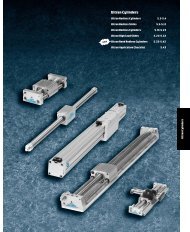
<strong>Linear</strong> <strong>Thrusters</strong><br />
Pneu-Moment
Bimba <strong>Linear</strong> <strong>Thrusters</strong><br />
<strong>Linear</strong> <strong>Thrusters</strong><br />
Pneu-Moment<br />
304 stainless steel body<br />
air cylinder with 303<br />
stainless steel piston rod<br />
Large diameter<br />
303 stainless<br />
steel shafts<br />
Composite<br />
bearings<br />
Clear anodized<br />
aluminum<br />
housing and<br />
tooling plate<br />
ADVANTAGES<br />
• Bimba stainless steel body air cylinders for long,<br />
reliable life.<br />
• Optional magnetic piston for use with Hall Effect or<br />
Magnetic Reed Switches. (Hall Effect Switch not<br />
available for 9/16" bore.)<br />
• Optional adjustable cushions for smooth deceleration<br />
of load at end of stroke. (Not available for 9/16".)<br />
• Optional internal or external bumpers to absorb<br />
shock or adjust stroke.<br />
• Easily accessible ports.<br />
• Choice of TE (composite bearing) and T(ball bearing).<br />
304 stainless steel body<br />
air cylinder with 303<br />
stainless steel piston rods<br />
Case hardened<br />
steel shafts<br />
Shaft collars<br />
TE SERIES<br />
• Large diameter stainless steel shafts (hard chrome<br />
plated carbon steel on 2-1/2" and 3" bores).<br />
• Mounting plate and shaft collars optional.<br />
• High-strength composite bearing made of<br />
fiber-imbedded plastic.<br />
• Composite bearing may perform better in certain<br />
environments (for example, dust or lint).<br />
• Composite bearing/stainless steel shaft<br />
combination is ideal for corrosive environments.<br />
• High load capabilities.<br />
Precision<br />
recirculating<br />
ball bearings<br />
Black anodized<br />
aluminum housing<br />
and mounting plate<br />
TSERIES<br />
• Less friction<br />
• High precision<br />
• Easily accessible lubrication ports<br />
• Mounting plate and shaft collars standard<br />
Steel tooling plate<br />
3.2
Bimba Extruded <strong>Linear</strong> <strong>Thrusters</strong><br />
Themodel number forExtruded<strong>Linear</strong><strong>Thrusters</strong> consists<br />
of three alphanumeric clusters. These designate product<br />
type, bore size and stroke length, and options.<br />
ET<br />
ETS<br />
ETD<br />
Please note the following features are standard, and<br />
are included in all model numbers: E(inch-series<br />
threading), and M(magnet for position sensing).<br />
Model Bore Sizes Options<br />
Extruded Thruster<br />
12 -12mm<br />
U.S. Customary Units<br />
-<br />
Extended Shafts; 4bushings<br />
16 - 16mm E Inch Series Porting/Mounting<br />
Extruded Thruster<br />
20 -20mm *Standard; included in all model numbers<br />
-<br />
Shafts Flush; 2bushings<br />
External Bumpers<br />
25 - 25mm<br />
EB External Bumpers, Retract<br />
Extruded Thruster<br />
-<br />
32 -32mm<br />
EB1 External Bumpers, Extend<br />
Double-end; Saddle Mount<br />
EB2 External Bumpers, Both Ends<br />
ETS -EB available only<br />
ET -16100 -EK12M<br />
No Stroke ReductionwithBumpers<br />
Extend Bumpers include One Set of Collars<br />
Shock Absorbers<br />
K_ _ First _will be: 1-BothEnds<br />
2-Extend Only<br />
Exceptions<br />
ET with Option K<br />
(Shock Absorbers)<br />
Minimum Stroke Length<br />
26mm N/A 26mm<br />
26mm N/A 26mm<br />
26mm N/A 26mm<br />
39mm 16mm 39mm<br />
42mm 45mm 42mm<br />
ET with Option X<br />
(Ball Bearings)<br />
Standard Stroke Lengths<br />
5mm Increments to 255mm<br />
The Bimba Extruded Thruster is arugged, guided<br />
actuator with acylinder integral to the thruster block.<br />
The sleak body incorporates switch mounting, for a<br />
clean, space-efficient package.<br />
HowtoOrder<br />
ETD withOptionX<br />
Only 2Bushings(not 4)<br />
when stroke is less than<br />
List Prices<br />
Second _will be:<br />
3-Retract Only<br />
1-Light Duty<br />
2-Medium Duty<br />
3-HeavyDuty<br />
ETS -K3 available only(retract only)<br />
See Minimum Stroke Note in Stroke Table<br />
Magnetic Position Sensing<br />
M MRS PositionSensing<br />
*Standard; included in all model numbers<br />
Alternate Port Location<br />
P Ports onTop Surface<br />
Must be specificed if Option Xisordered<br />
Fluoroelastomer Seals<br />
V High Temperature(0to275 deg F)<br />
Ball Bushings<br />
X Ball Bushings and HardenedShafts<br />
Must specifyOptionPwith XOption<br />
Model Type 12mm<br />
16mm 20mm 25mm 32mm<br />
ET (extended shafts, 4bushings) $143.65<br />
$155.50 $166.30 $187.60 $246.55<br />
add per 5mm stroke 0.70<br />
0.80 0.85 0.90 1.30<br />
ETS (shafts flush, 2bushings) 140.80<br />
152.45 163.00 183.90 241.70<br />
add per 5mm stroke 0.65 0.70 0.75 0.80 1.05<br />
ETD (double-end, saddle mount) 158.05 171.10 182.95 206.40 271.25<br />
add per 5mm stroke 0.70 0.80 0.85 0.90 1.30<br />
Extruded <strong>Linear</strong><br />
<strong>Thrusters</strong><br />
(Composite Bearings)<br />
(Ball Bearings)<br />
TE Series<br />
TSeries<br />
Multiple Position<br />
<strong>Linear</strong> <strong>Thrusters</strong><br />
<strong>Linear</strong> <strong>Thrusters</strong><br />
Checklist<br />
(PneumaticActuators)<br />
(Application Checklist)<br />
<strong>PneuMoment</strong><br />
Pneu Moment<br />
Options 12mm 16mm 20mm 25mm 32mm<br />
EB (External Bumpers, Retract) 6.95 6.95 9.25 11.50 13.85<br />
EB1 (External Bumpers, Extend) 20.70 20.70 25.30 30.45 34.45<br />
EB2 (External Bumpers, Both Ends) 27.60 27.60 34.45 41.90 48.20<br />
K__ (Shock Absorbers); Per End 94.85 120.05 134.15 149.10 161.25<br />
V(High Temperature Seals) 11.95 14.20 14.30 16.40 18.75<br />
X(Ball Bushings) ETS 57.35 57.35 68.85 71.70 83.50<br />
X(Ball Bushings) ET and ETD 114.70 114.70 137.65 143.35 166.90<br />
No Charge Options: P<br />
Included as Standard in Base: E, M<br />
All prices are F.O.B. Monee, Illinois and are subject to change without notice<br />
3.3 ForTechnical Assistance: 800-442-4622
Bimba Extruded <strong>Linear</strong> <strong>Thrusters</strong><br />
Engineering Specifications<br />
Maximum Operating Pressure 140 psi (10 bar)<br />
Temperature Range 15 to 160 degrees F(-10 to 70 degrees C)<br />
Expected Service Life 1,500 miles (with filtered, lubricated air)<br />
CylinderLubrication PTFE grease<br />
Bore<br />
Theoretical Cylinder Forces<br />
FORCE =Power Factor (PF) xInput Pressure<br />
PF xbar =kg; PF xpsi =pounds<br />
Input =PSI<br />
Input =Bar<br />
PF Extend PF Retract PF Extend PF Retract<br />
12mm 0.2 0.1 1.1 0.8<br />
16mm 0.3 0.2 2.0 1.5<br />
20mm 0.5 0.4 3.1 2.4<br />
25mm 0.8 0.6 4.9 3.8<br />
32mm 1.2 0.9 8.0 6.0<br />
Tooling Plate Endplay<br />
Maximum Tooling Plate Movement<br />
in Unloaded Condition (values in inches)<br />
ETS; with Standard Bearings<br />
Bore 25mm 50mm 75mm 100mm 125mm 150mm 175mm 200mm 225mm 250mm 275mm<br />
12mm 0.017 0.025 0.033 0.041 0.050 0.058 0.066 0.075 0.083 0.091 0.100<br />
16mm 0.017 0.025 0.033 0.041 0.050 0.058 0.066 0.075 0.083 0.091 0.100<br />
20mm 0.015 0.023 0.030 0.037 0.045 0.052 0.059 0.067 0.074 0.081 0.089<br />
25mm 0.013 0.019 0.024 0.030 0.035 0.041 0.046 0.052 0.057 0.063 0.069<br />
32mm 0.012 0.017 0.022 0.026 0.031 0.036 0.041 0.045 0.050 0.055 0.059<br />
ETS; with Ball Bearings<br />
Bore 25mm 50mm 75mm 100mm 125mm 150mm 175mm 200mm 225mm 250mm 275mm<br />
12mm 0.006 0.008 0.011 0.013 0.016 0.018 0.020 0.023 0.025 0.028 0.030<br />
16mm 0.006 0.008 0.011 0.013 0.016 0.018 0.020 0.023 0.025 0.028 0.030<br />
20mm 0.006 0.009 0.011 0.014 0.016 0.019 0.021 0.024 0.027 0.029 0.032<br />
25mm 0.005 0.006 0.008 0.009 0.011 0.013 0.014 0.016 0.018 0.019 0.021<br />
32mm 0.006 0.007 0.009 0.011 0.013 0.015 0.016 0.018 0.020 0.022 0.024<br />
ET and ETD; with Standard Bearings<br />
Bore 25mm 50mm 75mm 100mm 125mm 150mm 175mm 200mm 225mm 250mm 275mm<br />
12mm 0.005 0.005 0.006 0.006 0.006 0.006 0.006 0.006 0.006 0.006 0.006<br />
16mm 0.005 0.005 0.005 0.006 0.006 0.006 0.006 0.006 0.006 0.006 0.006<br />
20mm 0.005 0.006 0.006 0.006 0.006 0.006 0.006 0.006 0.006 0.006 0.007<br />
25mm 0.005 0.006 0.006 0.006 0.006 0.006 0.006 0.006 0.006 0.006 0.006<br />
32mm 0.006 0.006 0.007 0.007 0.007 0.007 0.007 0.007 0.007 0.007 0.007<br />
ET and ETD; with Ball Bearings<br />
Endplay on all ET and ETD <strong>Thrusters</strong> with Option "X" not to exceed .003"<br />
3.4
Bimba Extruded <strong>Linear</strong> <strong>Thrusters</strong><br />
2X “FF” X“EE” DP<br />
“U”<br />
“V”<br />
“W”<br />
“X”<br />
Dimensions -ET<br />
“B”<br />
“D”<br />
(OPTIONAL)<br />
“C” +STROKE<br />
“A” +2XSTROKE<br />
(OPP.SIDE)<br />
STROKE<br />
2X Ø“E”<br />
(OPTIONAL)<br />
2X Ø“F”<br />
(OPTIONAL)<br />
Extruded <strong>Linear</strong><br />
<strong>Thrusters</strong><br />
(Composite Bearings)<br />
TE Series<br />
2X “DD”<br />
“Y”<br />
“Z”<br />
“R” “S”<br />
“T”<br />
2X “H” PORTS<br />
(OPTIONAL TOP PORT)<br />
“G”<br />
(Ball Bearings)<br />
TSeries<br />
2X Ø“I”<br />
2X Ø“DD” X“EE” DP<br />
4X TAP “AA” THRU<br />
Ø“BB” C’BORE X“CC” DP (OPP.SIDE)<br />
“Q”<br />
“O”<br />
“P”<br />
“J”<br />
4X C’BORE Ø“K” X“L” DP<br />
TAP “M” X“N” DP (OPP.SIDE)<br />
Multiple Position<br />
<strong>Linear</strong> <strong>Thrusters</strong><br />
“KK”<br />
“GG” 2X “H” PORTS “HH”<br />
“II”<br />
<strong>Linear</strong> <strong>Thrusters</strong><br />
Checklist<br />
“JJ”<br />
Bore A B C D E F G H I<br />
12mm 3.20 .55 1.66 .25 .60 .95 2.00 #10-32 .39 (10mm)<br />
16mm 3.36 .55 1.81 .25 .60 .95 2.00 #10-32 .39 (10mm)<br />
20mm 3.79 .62 1.91 .25 .68 1.10 2.50 1/8 NPT .47 (12mm)<br />
25mm 3.90 .79 1.96 .25 .76 1.34 2.75 1/8 NPT .63 (16mm)<br />
32mm 4.43 .98 2.21 .25 .84 1.57 3.25 1/8 NPT .79 (20mm)<br />
Bore J K L M N O P Q R S<br />
12mm .43 .28 .16 #10-32 .50 .44 .88 .63 2.85 1.00<br />
16mm .43 .28 .16 #10-32 .50 .53 1.06 .65 2.85 1.00<br />
20mm .50 .38 .21 1/4-20 .63 .63 1.25 .79 3.50 1.39<br />
25mm .62 .38 .21 1/4-20 .63 .75 1.50 .79 3.99 1.39<br />
32mm .75 .47 .26 5/16-18 .77 .84 1.69 .85 4.75 1.65<br />
(PneumaticActuators)<br />
(Application Checklist)<br />
<strong>PneuMoment</strong><br />
Pneu Moment<br />
Bore T U V W X Y Z AA BB CC<br />
12mm .50 .86 .43 .50 .25 .50 1.00 #8-32 .25 .20<br />
16mm .50 .86 .43 .63 .31 .63 1.25 #8-32 .25 .20<br />
20mm .69 1.10 .55 .75 .38 .75 1.50 #10-32 .28 .20<br />
25mm .69 1.30 .65 .88 .44 .88 1.75 #10-32 .28 .30<br />
32mm .82 1.73 .87 1.00 .50 1.00 2.00 1/4-20 .33 .44<br />
Bore DD EE FF GG HH II JJ KK<br />
12mm .16 .14 .20 .48 .19 .98 .45 .37<br />
16mm .19 .20 .24 .51 .19 1.11 .45 .37<br />
20mm .19 .20 .24 .57 .32 1.36 .57 .49<br />
25mm .25 .24 .28 .57 .32 1.49 .73 .50<br />
32mm .25 .24 .28 .63 .32 1.98 .98 .58<br />
3.5 ForTechnical Assistance: 800-442-4622
Bimba Extruded <strong>Linear</strong> <strong>Thrusters</strong><br />
Dimensions -ETS<br />
“U”<br />
“V”<br />
“W”<br />
“X”<br />
“B”<br />
“A” +STROKE<br />
“D”<br />
(OPTIONAL)<br />
“C” +STROKE<br />
(OPP. SIDE)<br />
2X “FF” X“EE” DP<br />
2X “DD”<br />
“Y”<br />
“Z”<br />
“R” “S”<br />
“T”<br />
2X “H” PORTS<br />
(OPTIONAL TOP PORT)<br />
2X Ø“DD” X“EE” DP<br />
4X TAP“AA” THRU<br />
Ø“BB” C’BORE X“CC” DP (OPP.SIDE)<br />
“Q”<br />
“O”<br />
“P”<br />
4X C’BORE Ø“K” X“L” DP<br />
TAP “M” X“N” DP (OPP.SIDE)<br />
“GG”<br />
2X “H” PORTS<br />
“HH”<br />
“KK”<br />
“II”<br />
Bore A* B C D H K L M N O<br />
12mm 2.21 .55 1.66 .25 #10-32 .28 .16 #10-32 .50 .44<br />
16mm 2.36 .55 1.81 .25 #10-32 .28 .16 #10-32 .50 .53<br />
20mm 2.53 .62 1.91 .25 1/8 NPT .38 .21 1/4-20 .63 .63<br />
25mm 2.75 .79 1.96 .25 1/8 NPT .38 .21 1/4-20 .63 .75<br />
32mm 3.19 .98 2.21 .25 1/8 NPT .47 .26 5/16-18 .77 .84<br />
Bore P Q R S T U V W X Y<br />
12mm .88 .63 2.85 1.00 .50 .86 .43 .50 .25 .50<br />
16mm 1.06 .65 2.85 1.00 .50 .86 .43 .63 .31 .63<br />
20mm 1.25 .79 3.50 1.39 .69 1.10 .55 .75 .38 .75<br />
25mm 1.50 .79 3.99 1.39 .69 1.30 .65 .88 .44 .88<br />
32mm 1.69 .85 4.75 1.65 .82 1.73 .87 1.00 .50 1.00<br />
Bore Z AA BB CC DD EE FF GG HH II KK<br />
12mm 1.00 #8-32 .25 .20 .16 .14 .20 .48 .19 .98 .37<br />
16mm 1.25 #8-32 .25 .20 .19 .20 .24 .51 .19 1.11 .37<br />
20mm 1.50 #10-32 .28 .20 .19 .20 .24 .57 .32 1.36 .49<br />
25mm 1.75 #10-32 .28 .30 .25 .24 .28 .57 .32 1.49 .50<br />
32mm 2.00 1/4-20 .33 .44 .25 .24 .28 .63 .32 1.98 .58<br />
*Optional bumpers (EB) add .25" to overall length<br />
3.6
Bimba Extruded <strong>Linear</strong> <strong>Thrusters</strong><br />
TAP “DD” XTHRU<br />
“AA”<br />
“BB”<br />
“Z”<br />
“CC”<br />
Dimensions -ETD<br />
“D”<br />
(TYP)<br />
“W”<br />
“V” “Y”<br />
“U” “X”<br />
2X “B”<br />
1/2 (“C” +STROKE)<br />
2X “E”<br />
(OPTIONAL)<br />
“A” +2XSTROKE<br />
“C” +STROKE<br />
“F”<br />
“M” X“N” DP<br />
“G”<br />
2X “H”<br />
(OPTIONAL<br />
TOP PORT)<br />
“I”<br />
“J”<br />
Extruded <strong>Linear</strong><br />
<strong>Thrusters</strong><br />
(Composite Bearings)<br />
(Ball Bearings)<br />
TE Series<br />
TSeries<br />
4X C’BORE Ø“Q” X“R” DP<br />
TAP“S” X“T” DP (OPP.SIDE)<br />
“P”<br />
(TYP)<br />
(SEE “QTY OF THREADED MOUNTING HOLES” CHART)<br />
“O”<br />
2X “H” PORTS<br />
Ø“M” X“N” DP<br />
TAP“K” X“L” DP XQTY<br />
(SEE “QTY OF THREADED MOUNTING HOLES” CHART)<br />
Multiple Position<br />
<strong>Linear</strong> <strong>Thrusters</strong><br />
“II” “KK”<br />
Bore A* B C D E F G H I<br />
12mm 2.76 .55 1.66 .28 .25 .44 .20 #10-32 2.00<br />
16mm 2.91 .55 1.81 .28 .25 .53 .24 #10-32 2.00<br />
20mm 3.16 .62 1.91 .31 .25 .63 .24 1/8 NPT 2.50<br />
25mm 3.54 .79 1.96 .39 .25 .75 .28 1/8 NPT 2.75<br />
32mm 4.18 .98 2.21 .49 .25 1.69 .28 1/8 NPT 3.25<br />
Bore J K L M N O P** Q R S<br />
12mm .43 #10-32 .50 .16 .14 .88 .88 .36 .19 1/4-28<br />
16mm .43 #10-32 .50 .19 .20 1.06 1.00 .43 .26 5/16-24<br />
20mm .50 1/4-20 .63 .19 .20 1.25 1.25 .43 .27 5/16-24<br />
25mm .62 1/4-20 .63 .25 .24 1.50 1.50 .52 .32 3/8-24<br />
32mm .75 5/16-18 .77 .25 .24 1.69 1.69 .52 .32 3/8-24<br />
Bore T U V W X Y Z AA BB CC<br />
12mm .49 2.85 1.31 .66 1.00 .50 .84 .56 .28 1.13<br />
16mm .50 2.85 1.26 1.00 1.00 .50 .84 .56 .26 1.16<br />
20mm .68 3.50 1.69 1.25 1.39 .69 1.08 .64 .31 1.31<br />
25mm .58 3.99 1.76 1.38 1.39 .69 1.28 .95 .35 2.41<br />
32mm .80 4.75 2.13 1.63 1.65 .83 1.71 1.12 .41 1.83<br />
Bore DD EE FF GG HH II JJ KK<br />
12mm M8 x1.0 .48 .19 1.09 .39 (10mm) .98 .45 .37<br />
16mm M8 x1.0 .51 .19 1.22 .39 (10mm) 1.11 .45 .37<br />
20mm M10 x1.0 .57 .32 1.43 .47 (12mm) 1.36 .57 .49<br />
25mm M12 x1.0 .57 .32 1.70 .63 (16mm) 1.48 .73 .50<br />
32mm M14 x1.0 .63 .32 2.12 .79 (20mm) 1.98 .98 .58<br />
**Quantity of Threaded Mounting Holes<br />
Bore<br />
4 8 12 16 20 24<br />
For stroke lengths (mm):<br />
12mm 13.5 -57.9 58.0 -102.3 102.4 -146.8 146.9 -191.2 191.3 -235.7 235.8 -254.0<br />
16mm 16.0 -69.6 69.7 -123.6 123.7 -177.6 177.7 -231.6 231.7 -254.0 N/A<br />
20mm 26.0 -89.3 89.4 -152.8 152.9 -216.3 216.4 -254.0 N/A N/A<br />
25mm 31.0 -107.0 107.1 -183.2 183.3 -254.0 N/A N/A N/A<br />
32mm 33.0 -118.6 118.7 -203.6 203.7 -254.0 N/A N/A N/A<br />
*Optional bumpers (EB, EB1, EB2) add .25" per end to overall length<br />
“JJ”<br />
Ø“HH”<br />
“GG”<br />
<strong>Linear</strong> <strong>Thrusters</strong><br />
Checklist<br />
(PneumaticActuators)<br />
(Application Checklist)<br />
<strong>PneuMoment</strong><br />
Pneu Moment<br />
3.7 ForTechnical Assistance: 800-442-4622
Bimba Extruded <strong>Linear</strong> <strong>Thrusters</strong><br />
Dimensions<br />
Options-ET with Shock Absorbers<br />
“H” (TYP)<br />
2X “C”<br />
“A” +2XSTROKE<br />
2X “B”<br />
2X “E”<br />
2X “D”<br />
“F”<br />
“G”<br />
Bore A B C D E F G H<br />
12mm 3.20 0.23 0.06 0.89 M8 x1.0 1.91 3.34 0.20<br />
16mm 3.36 0.23 0.06 0.89 M8 x1.0 1.91 3.34 0.33<br />
20mm 3.79 0.31 0.11 0.82 M10 x1.0 2.42 4.17 0.79<br />
25mm 3.90 0.39 0.12 1.57 M12 x1.0 2.71 4.70 0.36<br />
32mm 4.43 0.47 0.10 2.77 M14 x1.0 3.23 5.60 0.56<br />
Dimensions<br />
Options-ETS with Shock Absorbers<br />
“H”<br />
“C”<br />
“A” +2XSTROKE<br />
“B”<br />
“E”<br />
“D”<br />
“F”<br />
“G”<br />
Bore A B C D E F G H<br />
12mm 2.46 0.23 0.06 0.89 M8x1.0 1.91 3.34 0.20<br />
16mm 2.61 0.23 0.06 0.89 M8 x1.0 1.91 3.34 0.33<br />
20mm 2.78 0.31 0.11 0.82 M10 x1.0 2.42 4.17 0.79<br />
25mm 3.00 0.39 0.12 1.57 M12 x1.0 2.71 4.70 0.36<br />
32mm 3.44 0.47 0.10 2.77 M14 x1.0 3.23 5.60 0.56<br />
3.8
Bimba Extruded <strong>Linear</strong> <strong>Thrusters</strong><br />
Dimensions<br />
Options-ETD with Shock Absorbers<br />
Extruded <strong>Linear</strong><br />
<strong>Thrusters</strong><br />
E<br />
(TYP)<br />
(Composite Bearings)<br />
TE Series<br />
A<br />
(TYP)<br />
B<br />
(TYP)<br />
(Ball Bearings)<br />
TSeries<br />
C<br />
(TYP)<br />
D<br />
(TYP)<br />
Bore A B C D E<br />
12mm 0.57 0.55 M8 x1.0 0.28 0.30<br />
16mm 0.57 0.55 M8 x1.0 0.26 0.27<br />
20mm 0.51 0.62 M10 x1.0 0.31 0.44<br />
25mm 1.17 0.79 M12 x1.0 0.35 0.42<br />
32mm 2.25 0.99 M14 x1.0 0.41 0.55<br />
Multiple Position<br />
<strong>Linear</strong> <strong>Thrusters</strong><br />
<strong>Linear</strong> <strong>Thrusters</strong><br />
Checklist<br />
1<br />
2<br />
3<br />
4<br />
Components/Materials of Construction<br />
5<br />
6<br />
7<br />
8<br />
9<br />
15<br />
11<br />
10<br />
13<br />
12<br />
14<br />
Item # Description Material<br />
1 Assembly Bolt Zinc-Plated Steel<br />
2 Tooling Plate Anodized Aluminum<br />
3 Piston Rod Hard Chrome Plated Stainless Steel<br />
4 Retaining Ring Zinc-Plated Steel<br />
5 Rod Seal Nitrile (Fluoroelastomer optional)<br />
6 Rod Guide Seal Nitrile (Fluoroelastomer optional)<br />
7 Rod Guide Anodized Aluminum<br />
8 Bumper Urethane<br />
9 Piston Seal Nitrile (Fluoroelastomer optional)<br />
10 Magnet Nitrile<br />
11 Piston Aluminum<br />
12 Body Anodized Aluminum<br />
13 Guide Bushing<br />
Self-Lubricating Nylon<br />
Ball Bushings optional<br />
14 Guide Shaft<br />
Hard Chrome Plated Stainless Steel<br />
Case Hardened Steel with XOption<br />
15 Rear Head Anodized Aluminum<br />
(PneumaticActuators)<br />
(Application Checklist)<br />
<strong>PneuMoment</strong><br />
Pneu Moment<br />
Basic Repair Kit includes: Piston Seals, Rod Seal, and Rod Guide Seal.<br />
Specify as K-B-ET-(bore size) -V(if applicable)<br />
Kit<br />
K-B-ET-__<br />
K-B-ET-__-V<br />
Bore<br />
12mm 16mm 20mm 25mm 32mm<br />
$8.15 $8.50 $9.30 $9.90 $10.45<br />
12.75 14.85 15.10 17.40 20.85<br />
All prices are F.O.B. Monee, Illinois and are subject to change without notice<br />
3.9 ForTechnical Assistance: 800-442-4622
Bimba Extruded <strong>Linear</strong> <strong>Thrusters</strong><br />
Maximum Side Load<br />
P<br />
P<br />
Maximum Load "P" as shown for ET, ETS, ETD<br />
with Standard Bearings (pounds)<br />
ETS; by Stroke<br />
Bore ET ETD 25mm 50mm 75mm 100 mm 125mm 150mm 175mm 200mm 225mm 250mm 275mm<br />
12mm 19 64 3.5 2.2 1.6 1.3 1.0 0.9 0.8 0.7 0.6 0.6 0.5<br />
16mm 19 64 3.5 2.2 1.6 1.3 1.0 0.9 0.8 0.7 0.6 0.6 0.5<br />
20mm 26 92 5.6 3.7 2.8 2.2 1.8 1.6 1.4 1.2 1.1 1.0 0.9<br />
25mm 43 156 11.1 7.5 5.7 4.6 3.8 3.3 2.9 2.6 2.3 2.1 1.9<br />
32mm 68 255 21.5 15.0 11.6 9.4 7.9 6.8 6.0 5.4 4.9 4.4 4.1<br />
Maximum Load "P" as shown for ET, ETS, ETD<br />
with Ball Bearings, Option "X" (pounds)<br />
For Ball Bearing model, use 2x Load Rating for Standard Bearings in above table.<br />
Maximum Moments<br />
Mc<br />
Mr<br />
Maximum Radial Moment (Mr) as shown for ET, ETS, ETD<br />
Standard Bearings (inch-pounds)<br />
Standard Bearings<br />
Bore ET/ETD ETS<br />
12mm 64 32<br />
16mm 64 32<br />
20mm 115 57<br />
25mm 214 107<br />
32mm 414 207<br />
For Ball Bearing model,use 2x MomentRatingfor Standard Bearings in above table.<br />
Maximum Axial (Ma) and Cross (Mc) Moments asshown for ETD<br />
Standard Bearings (inch-pounds)<br />
ETD; by Stroke<br />
Bore 25mm 50mm 75mm 100mm 125mm 150mm 175mm 200mm 225mm 250mm 275mm<br />
12mm 72 104 136 168 200 232 264 296 328 360 392<br />
16mm 77 109 141 173 205 237 269 301 332 365 370<br />
20mm 112 158 203 250 295 341 387 433 478 525 570<br />
25mm 184 262 340 417 495 573 650 729 806 885 960<br />
32mm 309 437 564 690 819 947 1074 1200 1329 1457 1584<br />
For Ball Bearing model, use 2x Moment Rating for Standard Bearings in above table.<br />
Mr<br />
Mc<br />
3.10
Bimba <strong>Linear</strong> <strong>Thrusters</strong>-TE Series (Composite Bearings)<br />
The model number of all <strong>Linear</strong> <strong>Thrusters</strong> consists of<br />
three alphanumeric clusters. These designate product<br />
type, bore size and stroke length, and options. Please<br />
refer to the charts below for an example of model<br />
HowtoOrder<br />
TE-098-EB1M<br />
number TE-098-EB1M. This is a1-1/16" bore, 8"<br />
stroke TE series <strong>Linear</strong> Thruster with extension<br />
external bumpers and amagnet for position sensing.<br />
Extruded <strong>Linear</strong><br />
<strong>Thrusters</strong><br />
(Composite Bearings)<br />
TE Series<br />
BORE SIZE<br />
02 - 9/16"<br />
04 - 3/4"<br />
09 - 1-1/16"<br />
17 - 1-1/2"<br />
31 - 2"<br />
50 - 2-1/2"<br />
70 - 3"<br />
STANDARD STROKE LENGTHS*<br />
1" increments to 6"<br />
1" increments to 12"<br />
1" increments to 12"<br />
1" increments to 12"<br />
1" increments to 12"<br />
1" increments to 12"<br />
1" increments to 12"<br />
*Stroke lengths beyond maximum<br />
are available; the rear of the<br />
cylinder must be supported in<br />
horizontal applications.<br />
OPTIONS<br />
B - Internal bumpers, both ends 1<br />
C - Adjustable cushions, both ends 1<br />
D - Dowel pin holes for Transition Plate 2<br />
EB1 - External bumpers, extension (one set) (see page 3.14)<br />
EB2 - External bumpers, both ends (two sets) (see page 3.14)<br />
K__ - Shock absorbers 3<br />
First _will be: 1-Shock both ends<br />
2-Shock extend only<br />
3-Shock retract only<br />
Second _will be: 1-Light shock<br />
2-Standard shock<br />
3-Heavy shock<br />
M - MRS ® magnetic position sensing 4<br />
H - Tapped holes<br />
P - Mounting plate (includes 12 tapped holes)<br />
S - Stainless steel tooling plate and optional shaft collars<br />
(Ball Bearings)<br />
TSeries<br />
Multiple Position<br />
<strong>Linear</strong> <strong>Thrusters</strong><br />
<strong>Linear</strong> <strong>Thrusters</strong><br />
Checklist<br />
1 Internal bumpers and cushions cannot be ordered in<br />
combination. Adjustable cushions are not available for 9/16"<br />
bore size.<br />
2 Transition Plate Applications: Option -H or -P must be<br />
ordered. Option-D must also be ordered if dowel pin holes<br />
are required. Not available in 2-1/2" and 3" bores with S<br />
option. Dowel pin hole locations shown in Appendix.<br />
3 See Ultran Cylinders, page 5.18 for more information. Shocks<br />
not available on 2-1/2" and 3" bores.<br />
4 Hall Effect Switch not available for 9/16" bore size.<br />
NOTE: TE Series <strong>Linear</strong> Thruster includes shaft collars only<br />
when external bumpers are ordered as an option (see page<br />
3.14). Shaft collars can also be ordered separately as arepair<br />
part.<br />
(PneumaticActuators)<br />
(Application Checklist)<br />
<strong>PneuMoment</strong><br />
Pneu Moment<br />
Approximate Power Factors<br />
9/16" = 0.2<br />
3/4" = 0.4<br />
1-1/16" = 0.9<br />
1-1/2" = 1.7<br />
2" = 3.1<br />
2-1/2" = 5.0<br />
3" = 7.0<br />
For example, aTE-046-EB1M will exert<br />
aforce of 0.4 times the air line pressure;<br />
aTE-173-EB1M will exert aforce of 1.7<br />
times the air pressure, etc.<br />
3.11 ForTechnical Assistance: 800-442-4622
Bimba <strong>Linear</strong> <strong>Thrusters</strong>-TE Series (Composite Bearings)<br />
Basic Model<br />
List Prices<br />
Base Price by Bore Size<br />
9/16" 3/4" 1-1/16" 1-1/2" 2" 2-1/2" 3"<br />
TE $168.90 $182.90 $220.70 $313.40 $463.95 $755.80 $1237.85<br />
Adder per 1"<br />
of Stroke<br />
3.25 3.75 4.20 5.95 7.90 6.95 7.50<br />
Options<br />
Adders by Bore Size<br />
9/16" 3/4" 1-1/16" 1-1/2" 2" 2-1/2" 3"<br />
B-Internal Bumpers, Both Ends $4.15 $4.15 $4.15 $5.10 $6.55 $6.25 $8.10<br />
C-Adjustable Cushions, Both Ends N/A 13.60 15.15 17.65 29.00 34.45 39.10<br />
D-Dowel Pin Holes— Standard Tooling Plate 5.90 7.55 10.95 14.70 15.00 21.65 30.35<br />
D-Dowel Pin Holes—Stainless Steel Tooling Plate 8.85 10.40 17.50 22.70 24.55 N/A N/A<br />
EB1-External Bumpers, Extension (1 set) 32.70 34.55 37.95 41.30 47.95 83.35 132.50<br />
EB1-with S-Option 46.70 49.25 54.15 59.05 68.50 N/A N/A<br />
EB2-External Bumpers, Both Ends (2 sets) 58.45 60.25 65.45 70.55 82.00 155.15 247.65<br />
EB2-with S-Option 83.50 85.95 93.55 100.75 117.00 N/A N/A<br />
H-12 Tapped Holes 6.75 6.75 6.75 8.15 9.30 29.80 42.65<br />
K-Shock Absorbers, Per End 94.85 120.05 134.15 161.25 215.75 N/A N/A<br />
M-MRS Magnetic Position Sensing 9.70 9.70 12.10 14.55 16.95 16.15 28.70<br />
P-Mounting Plate* 22.95 25.85 31.60 43.20 57.50 94.50 133.25<br />
S-Stainless Steel Tooling Plate 37.65 41.90 56.55 64.80 120.45 356.35 424.60<br />
*Option Pincludes 12tapped holes (option H)<br />
Engineering Data<br />
• Rated 250 psi<br />
• Low breakaway friction<br />
Components:<br />
• 303 stainless steel shafts<br />
• Clear anodized aluminum housing and tooling plate<br />
• Plastic composite guide shaft bearings<br />
Cylinder:<br />
• 304 stainless steel body<br />
• High-strength aluminum alloy porting ends<br />
• 303 stainless steel piston rods<br />
• Buna N"U" cup seals<br />
• Sintered bronze rod guide bushing<br />
Options:<br />
• Internal Buna Norexternal urethane bumpers<br />
• Patented adjustable cushions*<br />
• Buna Nmagnet for position sensing<br />
Temperature Range:<br />
Buna Nseals with atemperature range of -20°F<br />
(-25°C) to 200°F (95°C) are standard inall BIMBA air<br />
cylinders. High temperature option Aseals rated for<br />
higher temperature applications are available. If<br />
cylinders are operated at temperatures below 0°F<br />
for extended time periods, special modifications<br />
may be required. Special seal materials are available<br />
on request.<br />
With -M option: -20°F to +185°F (-25°C to +85°C).<br />
Lubrication:<br />
Air cylinders are pre-lubricated and sealed at the<br />
factory for extensive maintenance-free life. Cylinder<br />
life can be lengthened by providing additional lubricant<br />
with an air line mist lubricator or direct introduction<br />
of oil to the cylinder every 500 hours of operation.<br />
Recommended oils are medium to heavy<br />
inhibited hydraulic and general purpose oil.<br />
* U.S. Patent nos. 4,794,681 and 4,862,786<br />
All prices are F.O.B. Waco, Texas and are subject to change without notice<br />
3.12
Bimba <strong>Linear</strong> <strong>Thrusters</strong>-TE Series (Composite Bearings)<br />
UU<br />
TT<br />
WW<br />
Y<br />
Dimensions (in.)<br />
X<br />
W *<br />
L+STROKE<br />
V<br />
N<br />
T<br />
Q<br />
E<br />
N<br />
M<br />
P<br />
2Q<br />
Extruded <strong>Linear</strong><br />
<strong>Thrusters</strong><br />
QQ B<br />
HH<br />
GG<br />
FF<br />
CC<br />
S<br />
R<br />
J<br />
A<br />
K<br />
H<br />
C<br />
B<br />
(Composite Bearings)<br />
TE Series<br />
KK<br />
ZZ<br />
SS<br />
RR<br />
MM<br />
DRILL &CBORE<br />
FOR JJ SOCKET<br />
HEAD CAP<br />
SCREW 4PLCS<br />
Z<br />
DD<br />
DRILL &CBORE FOR<br />
JJ SOCKET HEAD CAP<br />
SCREW 4PLCS<br />
OPTIONAL BB 4PLCS<br />
EE 2PLCS OPP SIDE<br />
OPTIONAL MOUNTING PLATE<br />
*9/16" (02) model: Drawing is not an accurate depiction.<br />
Bore A B C D E F G H J K L M N P Q<br />
9/16" (02) 3.50 2.50 1.25 0.22 1.00 0.31 0.38 1.75 0.38 3.00 3.50 0.12 0.75 0.50 0.25<br />
3/4" (04) 4.50 3.00 1.50 0.25 1.25 0.38 0.50 2.12 0.44 3.75 4.25 0.16 0.94 0.62 0.38<br />
1-1/16" (09) 6.25 4.25 2.12 0.38 2.00 0.50 1.00 3.12 0.56 5.25 5.00 0.31 1.38 1.00 0.50<br />
1-1/2" (17) 7.50 5.50 2.75 0.44 2.50 0.59 1.31 4.00 0.75 6.50 6.38 0.38 1.75 1.25 0.50<br />
2" (31) 8.00 6.00 3.00 0.44 3.00 0.75 1.50 4.25 0.88 7.00 7.12 0.50 2.00 1.50 0.50<br />
2-1/2" (50) 11.50 7.50 3.75 0.69 3.50 0.84 1.81 5.37 1.06 9.50 9.75 0.50 2.50 1.75 1.00<br />
3" (70) 13.00 9.00 4.50 0.81 4.50 1.15 2.19 6.50 1.25 11.00 11.50 0.75 3.00 2.25 1.00<br />
U<br />
OPTIONAL<br />
BB 8PLCS<br />
OPTIONAL SHAFT COLLAR<br />
(STANDARD WITH EB OPTION<br />
OR ORDERED SEPARATELY)<br />
Bore R S T U V W X Y Z AA BB CC DD EE<br />
9/16" (02) 0.88 0.38 0.34 0.60 2.25 1.25 0.25 0.38 0.86 0.75 8-32 0.62 6-32 10-32<br />
3/4" (04) 1.12 0.50 0.41 0.52 2.50 0.78 0.38 0.50 0.85 1.00 10-32 0.81 8-32 1/8 NPT<br />
1-1/16" (09) 1.31 0.62 0.44 0.98 3.00 0.81 0.38 0.62 1.00 1.50 1/4-20 1.12 10-32 1/8 NPT<br />
1-1/2" (17) 1.50 0.75 0.50 1.57 4.00 1.12 0.50 0.75 1.38 2.00 5/16-18 1.56 1/4-28 1/8 NPT<br />
2" (31) 1.62 0.88 0.50 1.07 4.00 1.00 0.75 1.00 1.60 2.25 5/16-18 2.08 1/4-28 1/4 NPT<br />
21/2" (50) 1.87 1.13 0.50 2.20 6.00 1.75 0.75 1.25 1.45 3.00 3/8-16 2.62 1/4-28 1/4-NPT<br />
3" (70) 2.25 1.38 0.56 3.73 7.00 2.00 1.00 1.50 1.62 3.50 1/2-13 3.12 1/4-28 3/8 NPT<br />
G<br />
F<br />
AA<br />
D<br />
(Ball Bearings)<br />
TSeries<br />
Multiple Position<br />
<strong>Linear</strong> <strong>Thrusters</strong><br />
<strong>Linear</strong> <strong>Thrusters</strong><br />
Checklist<br />
(PneumaticActuators)<br />
(Application Checklist)<br />
<strong>PneuMoment</strong><br />
Pneu Moment<br />
Bore FF GG HH JJ KK MM QQ RR SS TT UU WW ZZ<br />
9/16" (02) 0.69 1.00 7/16-20 #8 10-32 0.19 1.25 0.63 0.45 0.60 0.90 0.15 #10-32<br />
3/4" (04) 0.94 1.25 5/8-18 #10 1/4-28 0.25 1.50 0.75 0.58 0.75 1.15 0.20 1/4-20<br />
1-1/16" (09) 1.12 1.88 5/8-18 1/4 5/16-24 0.31 2.00 1.12 0.88 1.00 1.75 0.38 5/16-18<br />
1-1/2" (17) 1.12 2.38 3/4-16 5/16 7/16-20 0.44 3.00 1.25 1.12 1.50 2.25 0.38 3/8-16<br />
2" (31) 1.25 2.70 1-1/4-12 5/16 1/2-20 0.62 3.00 1.50 1.38 2.00 2.75 0.38 3/8-16<br />
2-1/2" (50) 1.50 3.50 13/8-12 3/8 1/2-20 0.63 3.75 1.88 1.63 2.25 3.25 0.50 1/2-13<br />
3" (70) 1.75 4.20 11/2-12 1/2 5/8-18 0.75 4.50 2.25 2.00 2.75 4.00 0.63 3/4-16<br />
<strong>Linear</strong> <strong>Thrusters</strong> ordered with adjustable cushions incorporate aside port on rear of cylinder.<br />
3.13 ForTechnical Assistance: 800-442-4622
Bimba <strong>Linear</strong> <strong>Thrusters</strong>-TE Series (Composite Bearings)<br />
Repair Parts<br />
Add the bore size to the basic model number shown<br />
below. For the Basic Shaft, specify the stroke length<br />
in inches and indicate options -EB1 or -EB2 as<br />
applicable. For example, shaft collars for a1-1/16"<br />
bore <strong>Linear</strong> Thruster Series TE would be SCTE-09.<br />
The Basic Shaft for the same thruster with 8-1/2"<br />
stroke would be BSTE-09-8.5. Cylinder repair part<br />
number corresponds to number shown on cylinder<br />
shipped with <strong>Linear</strong> Thruster.<br />
Part # Description Quantity<br />
BTE- Shaft Bearing 4<br />
BSTE- -X.XX Basic Shaft 2<br />
EBTE- External Bumper 2or4<br />
LT-Bore Stroke-D Cylinder 1<br />
LT-Bore Stroke-DB Cylinder 1<br />
LT-Bore Stroke-DM* Cylinder 1<br />
LT-Bore Stroke-DBM* Cylinder 1<br />
LTC-Bore Stroke-D Cylinder 1<br />
LTC-Bore Stroke-DM Cylinder 1<br />
SCTE- Shaft Collars 2or4<br />
TNTE- Cylinder Lock Nut 1<br />
* For 1-1/16” bore use LTEprefix.<br />
External Bumpers<br />
Use and Dimensional Changes<br />
Guide Shaft<br />
Extention with<br />
Bumpers (in.)<br />
Bore<br />
Size<br />
Length<br />
Adder<br />
9/16" 0.5<br />
3/4" 0.5<br />
1-1/16" 0.63<br />
1-1/2" 0.75<br />
2" 0.875<br />
2-1/2" 1.38<br />
3" 1.50<br />
The stroke can be adjusted with external urethane<br />
bumpers. These are available on one or both ends<br />
(-EB1 and -EB2 options). They are 1/4" thick in all<br />
bore sizes, and fit over the guide shafts at the ends of<br />
the housing (see illustration). Shaft collars are<br />
supplied with each set of bumpers to eliminate movement<br />
possible with high loads and velocities. Thus,<br />
Bore Size<br />
Retraction Stroke Reduction<br />
with Bumpers (in.)<br />
Standard<br />
Reduction<br />
with Mounting<br />
Plate Option<br />
9/16" 0.34 0.59<br />
3/4" 0.28 0.66<br />
1-1/16" 0.31 0.69<br />
1-1/2" 0.25 0.75<br />
2" 0 0.75<br />
2-1/2" .25 1.00<br />
3" .31 1.31<br />
with -EB1 option, there will be atotal of two collars;<br />
with -EB2 option, there will be four shaft collars.<br />
Guide shafts are lengthened so stroke on<br />
extension isn't affected; however, bumpers reduce<br />
the retraction stroke (see charts above). Higher<br />
loads and velocities may dictate the use of external<br />
means of deceleration such as shock absorbers.<br />
3.14
Bimba <strong>Linear</strong> <strong>Thrusters</strong>-TE Series (Composite Bearings)<br />
1000<br />
SIDE LOAD (LBS) (LBS)<br />
100<br />
10<br />
TE-SIDE LOAD<br />
1<br />
0 5 10 15 20 25 30<br />
35 40 45 50 55<br />
STROKE (IN)<br />
10000<br />
MOMENT LOAD (IN-LBS) (IN-LBS)<br />
1000<br />
100<br />
10<br />
TE-MOMENT LOAD<br />
1 0 5 10 15 20 25 30 35 40 45 50 55<br />
(IN)<br />
STROKE (IN)<br />
Frictional characteristics of TE Series <strong>Linear</strong> <strong>Thrusters</strong><br />
deteriorate as stroke length increases.<br />
TE -Maximum Side Loads (lbs.)<br />
TE-02<br />
TE-04<br />
TE-09<br />
TE-17<br />
TE-31<br />
TE-50<br />
TE-70<br />
TE -Maximum Moments (in.-lbs.)<br />
TE-02<br />
TE-04<br />
TE-09<br />
TE-17<br />
TE-31<br />
TE-50<br />
TE-70<br />
TE-02 TE-04 TE-09 TE-17 TE-31 TE-50 TE-70<br />
0 76.52 133.95 210.00 328.24 425.18 752.44 1000.00<br />
1 55.80 102.00 165.60 273.00 359.17 661.79 999.87<br />
2 41.50 82.00 136.00 233.00 310.00 590.30 905.30<br />
3 31.00 66.00 116.00 199.00 271.00 532.45 826.67<br />
4 24.40 55.02 98.00 170.00 240.00 484.67 760.25<br />
5 19.96 45.50 86.00 144.00 211.67 444.52 703.38<br />
6 16.94 38.78 74.00 124.00 183.91 410.31 654.14<br />
7 14.65 33.77 65.00 109.00 162.33 380.80 611.07<br />
8 12.83 29.78 57.00 97.00 145.22 355.07 573.07<br />
9 11.44 26.71 52.00 87.00 131.26 332.44 539.30<br />
10 10.32 24.11 47.00 79.00 119.66 312.38 509.07<br />
11 9.30 21.99 43.00 72.00 109.74 294.46 481.85<br />
12 8.54 20.16 39.00 66.00 101.38 278.35 457.20<br />
13 7.95 18.81 36.46 62.03 95.03 263.80 434.78<br />
14 7.43 17.61 34.20 58.48 89.66 250.57 414.28<br />
15 6.96 16.53 32.17 55.27 84.80 238.50 395.47<br />
16 6.54 15.57 30.35 52.36 80.39 227.44 378.15<br />
17 6.16 14.70 28.69 49.71 76.36 217.25 362.13<br />
18 5.82 13.90 27.18 47.28 72.67 207.85 347.28<br />
19 5.51 13.18 25.79 45.05 69.26 199.14 333.46<br />
20 5.22 12.51 24.52 42.99 66.12 191.04 320.58<br />
21 4.95 11.89 23.34 41.08 63.20 183.49 308.53<br />
22 4.71 11.32 22.25 39.31 60.49 176.43 297.23<br />
23 4.48 10.79 21.23 37.66 57.96 169.82 286.62<br />
24 4.27 10.30 20.29 36.12 55.59 163.62 276.63<br />
25 4.07 9.84 19.40 34.67 53.37 157.77 267.21<br />
26 3.89 9.41 18.57 33.31 51.28 152.26 258.30<br />
27 3.71 9.00 17.79 32.03 49.32 147.06 249.87<br />
28 3.55 8.62 17.06 30.83 47.46 142.13 241.87<br />
29 3.39 8.25 16.36 29.69 45.70 137.46 234.28<br />
30 3.25 7.91 15.70 28.61 44.04 133.02 227.05<br />
31 3.11 7.59 15.08 27.58 42.46 128.79 220.17<br />
32 2.97 7.28 14.48 26.61 40.96 124.77 213.60<br />
33 2.85 6.98 13.92 25.68 39.52 120.93 207.32<br />
34 2.73 6.70 13.38 24.79 38.16 117.27 201.32<br />
35 2.61 6.43 12.86 23.95 36.85 113.76 195.58<br />
36 2.50 6.18 12.37 23.14 35.60 110.41 190.07<br />
37 2.40 5.93 11.90 22.37 34.41 107.19 184.78<br />
38 2.29 5.69 11.44 21.63 33.26 104.10 179.71<br />
39 2.20 5.47 11.01 20.91 32.16 101.13 174.82<br />
40 2.10 5.25 10.59 20.23 31.10 98.27 170.12<br />
41 2.01 5.04 10.19 19.57 30.08 95.52 165.60<br />
42 1.93 4.83 9.80 18.94 29.10 92.87 161.23<br />
43 1.84 4.64 9.42 18.33 28.15 90.32 157.01<br />
44 1.76 4.45 9.06 17.74 27.24 87.85 152.94<br />
45 1.68 4.26 8.71 17.17 26.35 85.47 149.01<br />
46 1.60 4.09 8.37 16.61 25.50 83.16 145.20<br />
47 1.53 3.91 8.04 16.08 24.67 80.93 141.52<br />
48 1.46 3.75 7.73 15.56 23.87 78.77 137.95<br />
49 1.39 3.58 7.42 15.06 23.09 76.67 134.49<br />
50 1.32 3.43 7.12 14.58 22.34 74.64 131.13<br />
TE-02 TE-04 TE-09 TE-17 TE-31 TE-50 TE-70<br />
0 66.96 142.32 328.12 656.48 903.51 2022.18 3623.75<br />
1 48.83 108.38 258.75 546.00 763.24 1778.57 3249.57<br />
2 36.31 87.13 212.50 466.00 658.75 1586.43 2942.22<br />
3 27.13 70.13 181.25 398.00 575.88 1430.96 2686.67<br />
4 21.35 58.46 153.13 340.00 510.00 1302.54 2470.80<br />
5 17.47 48.34 134.38 288.00 449.80 1194.65 2285.99<br />
6 14.82 41.20 115.63 248.00 390.81 1102.70 2125.94<br />
7 12.82 35.88 101.56 218.00 344.95 1023.39 1985.97<br />
8 11.23 31.64 89.06 194.00 308.59 954.26 1862.49<br />
9 10.01 28.38 81.25 174.00 278.93 893.44 1752.72<br />
10 9.03 25.62 73.44 158.00 254.28 839.52 1654.47<br />
11 8.14 23.36 67.19 144.00 233.20 791.36 1566.00<br />
12 7.47 21.42 60.94 132.00 215.43 748.08 1485.90<br />
13 6.95 19.98 56.97 124.07 201.93 708.96 1413.03<br />
14 6.50 18.71 53.44 116.95 190.52 673.41 1346.42<br />
15 6.09 17.57 50.27 110.54 180.20 640.97 1285.29<br />
16 5.72 16.54 47.41 104.72 170.83 611.24 1228.98<br />
17 5.39 15.62 44.82 99.42 162.27 583.87 1176.92<br />
18 5.09 14.77 42.46 94.56 154.41 558.60 1128.65<br />
19 4.82 14.00 40.30 90.10 147.18 535.18 1083.75<br />
20 4.57 13.29 38.31 85.98 140.50 513.41 1041.87<br />
21 4.34 12.64 36.47 82.17 134.30 493.13 1002.71<br />
22 4.12 12.03 34.76 78.62 128.54 474.16 966.01<br />
23 3.92 11.47 33.18 75.32 123.16 456.40 931.52<br />
24 3.74 10.94 31.70 72.23 118.13 439.72 899.05<br />
25 3.56 10.45 30.32 69.34 113.42 424.01 868.43<br />
26 3.40 9.99 29.02 66.62 108.98 409.21 839.48<br />
27 3.25 9.56 27.80 64.07 104.80 395.21 812.08<br />
28 3.10 9.15 26.65 61.65 100.86 381.97 786.09<br />
29 2.97 8.77 25.56 59.37 97.12 369.41 761.40<br />
30 2.84 8.41 24.53 57.21 93.59 357.48 737.91<br />
31 2.72 8.06 23.56 55.16 90.23 346.14 715.54<br />
32 2.60 7.73 22.63 53.21 87.03 335.33 694.19<br />
33 2.49 7.42 21.74 51.36 83.99 325.01 673.80<br />
34 2.39 7.12 20.90 49.59 81.09 315.16 654.30<br />
35 2.29 6.83 20.10 47.90 78.31 305.74 635.63<br />
36 2.19 6.56 19.33 46.28 75.66 296.71 617.73<br />
37 2.10 6.30 18.59 44.74 73.12 288.06 600.55<br />
38 2.01 6.05 17.88 43.25 70.68 279.76 584.05<br />
39 1.92 5.81 17.20 41.83 68.34 271.78 568.18<br />
40 1.84 5.58 16.55 40.46 66.09 264.10 552.90<br />
41 1.76 5.35 15.92 39.14 63.92 256.71 538.18<br />
42 1.68 5.14 15.31 37.87 61.83 249.59 523.99<br />
43 1.61 4.93 14.73 36.65 59.82 242.73 510.30<br />
44 1.54 4.73 14.16 35.47 57.88 236.09 497.07<br />
45 1.47 4.53 13.61 34.33 56.00 229.69 484.28<br />
46 1.40 4.34 13.08 33.23 54.19 223.49 471.91<br />
47 1.34 4.16 12.57 32.16 52.43 217.50 459.93<br />
48 1.28 3.98 12.07 31.13 50.73 211.69 448.33<br />
49 1.21 3.81 11.59 30.12 49.08 206.06 437.08<br />
50 1.15 3.64 11.12 29.15 47.47 200.60 426.16<br />
Extruded <strong>Linear</strong><br />
<strong>Thrusters</strong><br />
(Composite Bearings)<br />
(Ball Bearings)<br />
TE Series<br />
TSeries<br />
Multiple Position<br />
<strong>Linear</strong> <strong>Thrusters</strong><br />
<strong>Linear</strong> <strong>Thrusters</strong><br />
Checklist<br />
(PneumaticActuators)<br />
(Application Checklist)<br />
<strong>PneuMoment</strong><br />
Pneu Moment<br />
3.15 ForTechnical Assistance: 800-442-4622
Bimba <strong>Linear</strong> <strong>Thrusters</strong>-TE Series (Composite Bearings)<br />
TE -Tooling Plate End Play (in.)<br />
0.25<br />
TE-END PLAY<br />
0.20<br />
END END PLAY(IN)<br />
0.15<br />
0.10<br />
TE-02<br />
TE-04<br />
TE-09<br />
TE-17<br />
TE-31<br />
TE-50<br />
TE-70<br />
0.05<br />
0.00<br />
00 5 10 15 20 25 30 35 40 45 50 55<br />
STROKE (IN) (IN)<br />
TE-02 TE-04 TE-09 TE-17 TE-31 TE-50 TE-70<br />
0 0.006 0.007 0.006 0.006 0.007 0.006 0.006<br />
1 0.011 0.011 0.010 0.009 0.009 0.008 0.008<br />
2 0.015 0.015 0.013 0.011 0.012 0.010 0.009<br />
3 0.019 0.019 0.016 0.014 0.014 0.011 0.011<br />
4 0.024 0.023 0.020 0.016 0.017 0.013 0.012<br />
5 0.028 0.027 0.023 0.019 0.019 0.015 0.014<br />
6 0.033 0.031 0.026 0.021 0.022 0.016 0.015<br />
7 0.037 0.035 0.030 0.024 0.024 0.018 0.016<br />
8 0.042 0.039 0.033 0.026 0.027 0.020 0.018<br />
9 0.046 0.043 0.036 0.029 0.029 0.021 0.019<br />
10 0.051 0.047 0.040 0.031 0.032 0.023 0.021<br />
11 0.055 0.051 0.043 0.034 0.034 0.025 0.022<br />
12 0.059 0.055 0.046 0.036 0.037 0.026 0.024<br />
13 0.064 0.059 0.050 0.039 0.039 0.028 0.025<br />
14 0.068 0.063 0.053 0.041 0.042 0.030 0.026<br />
15 0.073 0.067 0.056 0.044 0.044 0.031 0.028<br />
16 0.077 0.071 0.060 0.046 0.047 0.033 0.029<br />
17 0.082 0.075 0.063 0.049 0.049 0.035 0.031<br />
18 0.086 0.079 0.066 0.051 0.052 0.036 0.032<br />
19 0.091 0.083 0.070 0.054 0.054 0.038 0.034<br />
20 0.095 0.087 0.073 0.056 0.057 0.040 0.035<br />
21 0.099 0.091 0.076 0.059 0.059 0.041 0.036<br />
22 0.104 0.095 0.080 0.061 0.062 0.043 0.038<br />
23 0.108 0.099 0.083 0.064 0.064 0.045 0.039<br />
24 0.113 0.103 0.086 0.066 0.067 0.046 0.041<br />
25 0.117 0.107 0.090 0.069 0.069 0.048 0.042<br />
26 0.122 0.111 0.093 0.071 0.072 0.050 0.044<br />
27 0.126 0.115 0.096 0.074 0.074 0.051 0.045<br />
28 0.131 0.119 0.100 0.076 0.077 0.053 0.046<br />
29 0.135 0.123 0.103 0.079 0.079 0.055 0.048<br />
30 0.139 0.127 0.106 0.081 0.082 0.056 0.049<br />
31 0.144 0.131 0.110 0.084 0.084 0.058 0.051<br />
32 0.148 0.135 0.113 0.086 0.087 0.060 0.052<br />
33 0.153 0.139 0.116 0.089 0.089 0.061 0.054<br />
34 0.157 0.143 0.120 0.091 0.092 0.063 0.055<br />
35 0.162 0.147 0.123 0.094 0.094 0.065 0.056<br />
36 0.166 0.151 0.126 0.096 0.097 0.066 0.058<br />
37 0.171 0.155 0.130 0.099 0.099 0.068 0.059<br />
38 0.175 0.159 0.133 0.101 0.102 0.070 0.061<br />
39 0.179 0.163 0.136 0.104 0.104 0.071 0.062<br />
40 0.184 0.167 0.140 0.106 0.107 0.073 0.064<br />
41 0.188 0.171 0.143 0.109 0.109 0.075 0.065<br />
42 0.193 0.175 0.146 0.111 0.112 0.076 0.066<br />
43 0.197 0.179 0.150 0.114 0.114 0.078 0.068<br />
44 0.202 0.183 0.153 0.116 0.117 0.080 0.069<br />
45 0.206 0.187 0.156 0.119 0.119 0.081 0.071<br />
46 0.211 0.191 0.160 0.121 0.122 0.083 0.072<br />
47 0.215 0.195 0.163 0.124 0.124 0.085 0.074<br />
48 0.219 0.199 0.166 0.126 0.127 0.086 0.075<br />
49 0.224 0.203 0.170 0.129 0.129 0.088 0.076<br />
50 0.228 0.207 0.173 0.131 0.132 0.090 0.078<br />
3.16
Bimba <strong>Linear</strong> <strong>Thrusters</strong>-T Series (Ball Bearings)<br />
The model number of all <strong>Linear</strong> <strong>Thrusters</strong> consists of<br />
three alphanumeric clusters. These designate product<br />
type, bore size and stroke length, and options. Please<br />
refer to the charts below for an example of model<br />
HowtoOrder<br />
T-046-CM<br />
number T-046-CM. This is a3/4" bore, 6" stroke <strong>Linear</strong><br />
Thruster with adjustable cushions and amagnet for<br />
position sensing.<br />
Extruded <strong>Linear</strong><br />
<strong>Thrusters</strong><br />
(Composite Bearings)<br />
TE Series<br />
BORE SIZE<br />
02 - 9/16"<br />
04 - 3/4"<br />
09 - 1-1/16"<br />
17 - 1-1/2"<br />
31 - 2"<br />
50 - 2-1/2"<br />
70 - 3"<br />
STANDARD STROKE LENGTHS*<br />
1" increments to 6"<br />
1" increments to 12"<br />
1" increments to 12"<br />
1" increments to 12"<br />
1" increments to 12"<br />
1" increments to 12"<br />
1" increments to 12"<br />
*Stroke lengths beyond maximum<br />
are available; the rear of the<br />
cylinder must be supported in<br />
horizontal applications.<br />
OPTIONS<br />
B - Internal bumpers, both ends 1<br />
C - Adjustable cushions, both ends 1<br />
D - Dowel pin holes for Transition Plate 2<br />
EB1 - External bumpers, extension (one set) (see page 3.20)<br />
EB2 - External bumpers, both ends (two sets) (see page 3.20)<br />
K__ - Shock absorbers 3<br />
First _will be: 1-Shock both ends<br />
2-Shock extend only<br />
3-Shock retract only<br />
Second _will be: 1-Light shock<br />
2-Standard shock<br />
3-Heavy shock<br />
M - MRS ® magnetic position sensing 4<br />
NP - Nomounting plate<br />
S - Stainless steel tooling plate, shafts and collars 5<br />
1 Internal bumpers and cushions cannot be ordered in<br />
combination. Adjustable cushions are not available for 9/16"<br />
bore size.<br />
2 Transition Plate Applications: Option-D must be ordered if<br />
dowel pin holes are required. Not available in 2-1/2" and 3"<br />
bores with Soption. Dowel pin hole locations shown in<br />
Appendix.<br />
(Ball Bearings)<br />
TSeries<br />
Multiple Position<br />
<strong>Linear</strong> <strong>Thrusters</strong><br />
<strong>Linear</strong> <strong>Thrusters</strong><br />
Checklist<br />
(PneumaticActuators)<br />
<strong>PneuMoment</strong><br />
3 Not available on 2-1/2" and 3" bores.<br />
4 Hall Effect Switch not available for 9/16" bore size.<br />
5 Not available in 2-1/2" and 3" bores.<br />
(Application Checklist)<br />
Pneu Moment<br />
Approximate Power Factors<br />
9/16" = 0.2<br />
3/4" = 0.4<br />
1-1/16" = 0.9<br />
1-1/2" = 1.7<br />
2" = 3.1<br />
2-1/2" = 5.0<br />
3" = 7.0<br />
For example, aT-046-CM will exert a<br />
force of 0.4 times the air line pressure;<br />
aT-173-M will exert aforce of 1.7 times<br />
the air pressure, etc.<br />
3.17 ForTechnical Assistance: 800-442-4622
Bimba <strong>Linear</strong> <strong>Thrusters</strong>-T Series (Ball Bearings)<br />
Basic<br />
Model<br />
Base Price by Bore Size<br />
9/16" 3/4" 1-1/16" 1-1/2" 2" 2-1/2" 3"<br />
T $297.95 $332.30 $347.95 $490.75 $681.30 $1342.15 $2543.45<br />
Adder per 1"<br />
of Stroke<br />
ListPrices<br />
3.80 3.80 4.00 5.70 6.30 6.95 8.10<br />
Options<br />
Adders by Bore Size<br />
9/16" 3/4" 1-1/16" 1-1/2" 2" 2-1/2" 3"<br />
B-Internal Bumpers, Both Ends $4.15 $4.15 $4.15 $5.10 $6.55 $6.25 $8.10<br />
C-Adjustable Cushions, Both Ends N/A 13.60 15.15 17.65 29.00 34.45 39.10<br />
D-Dowel Pin Holes— Standard Tooling Plate 5.90 7.55 10.95 14.70 15.00 21.65 30.35<br />
D-Dowel Pin Holes—Stainless Steel Tooling Plate 8.85 10.40 17.50 22.70 24.55 N/A N/A<br />
EB1-External Bumpers, Extension (1 set) 25.80 25.80 27.60 29.25 34.05 71.60 122.40<br />
EB1-with S-Option 36.55 36.55 40.20 47.55 58.45 N/A N/A<br />
EB2-External Bumpers, Both Ends (2 sets) 51.60 51.60 55.10 58.45 68.10 131.65 232.05<br />
EB2-with S-Option 73.05 73.05 80.40 95.00 116.85 111.25 111.25<br />
K-Shock Absorbers, Per End 94.85 120.05 134.15 161.25 215.75 N/A N/A<br />
M-MRS Magnetic Position Sensing 9.70 9.70 12.10 14.55 16.95 16.15 28.70<br />
NP-No Mounting Plate (Deduct from Price) (5.95) (7.15) (11.05) (16.85) (31.55) (56.85) (110.40)<br />
S-Stainless Steel Tooling Plate, Shafts and Collars (Base Price) 85.75 115.80 135.30 191.30 295.25 N/A N/A<br />
Adder Per Inch of Stroke 6.30 6.55 7.05 8.40 9.35 N/A N/A<br />
Engineering Data<br />
• Rated 250 psi<br />
• Low breakaway friction<br />
Components:<br />
• Case hardened steel shafts<br />
• Steel tooling plate and collars<br />
• Black anodized aluminum housing and mounting plate<br />
• Precision recirculating ball bearings<br />
Cylinder:<br />
• 304 stainless steel body<br />
• High-strength aluminum alloy porting ends<br />
• 303 stainless steel piston rods<br />
• Buna N"U" cup seals<br />
• Sintered bronze rod guide bushing<br />
Options:<br />
• Internal Buna Norexternal urethane bumpers<br />
• Patented adjustable cushions*<br />
• Buna Nmagnet for position sensing<br />
Temperature Range:<br />
Buna Nseals with atemperature range of -20°F<br />
(-25°C) to 200°F (95°C) are standard inall BIMBA air<br />
cylinders. High temperature option Aseals rated for<br />
higher temperature applications are available. If<br />
cylinders are operated at temperatures below 0°F for<br />
extended time periods, special modifications may be<br />
required. Special seal materials are available on<br />
request.<br />
With -M option: -20°F to +185°F (-25°C to +85°C)<br />
Lubrication:<br />
Air cylinders are pre-lubricated and sealed at the<br />
factory for extensive maintenance-free life. Cylinder life<br />
can be lengthened by providing additional lubricant<br />
with an air line mist lubricator or direct introduction of<br />
oil to the cylinder every 500 hours of operation. Recommended<br />
oils are medium to heavy inhibited<br />
hydraulic and general purpose oil.<br />
The two spring-loaded oiler ports on the housing face<br />
should also receive several drops of the same oil every<br />
100 hours of operation. For applications that involve<br />
rapid cycling, oil these ports more often.<br />
All prices are F.O.B. Waco, Texas and are subject to change without notice<br />
3.18
Bimba <strong>Linear</strong> <strong>Thrusters</strong>-T Series (Ball Bearings)<br />
UU<br />
TT<br />
WW<br />
Y<br />
X<br />
W *<br />
Dimensions<br />
L+STROKE<br />
V<br />
N<br />
OILER 2PLCS<br />
T<br />
Q<br />
E<br />
N<br />
M<br />
P<br />
2Q<br />
Extruded <strong>Linear</strong><br />
<strong>Thrusters</strong><br />
QQ B<br />
HH<br />
GG<br />
FF<br />
CC<br />
S<br />
R<br />
J<br />
A<br />
K<br />
H<br />
C<br />
B<br />
(Composite Bearings)<br />
TE Series<br />
KK<br />
ZZ<br />
SS<br />
RR<br />
MM<br />
DRILL &CBORE<br />
FOR JJ SOCKET<br />
HEAD CAP SCREW<br />
4PLCS<br />
Z<br />
DD<br />
DRILL &CBORE FOR<br />
JJ SOCKET HEAD CAP<br />
SCREW 4PLCS<br />
BB 4PLCS OPP SIDE<br />
EE 2PLCS<br />
* 9/16" (02) model: Drawing is not an accurate depiction.<br />
Bore A B C D E F G H J K L M N P Q R<br />
9/16" (02) 3.50 2.50 1.25 0.22 1.00 0.31 0.38 1.75 0.38 3.00 3.50 0.12 0.75 0.50 0.25 0.62<br />
3/4" (04) 4.50 3.00 1.50 0.25 1.25 0.38 0.50 2.12 0.44 3.75 4.12 0.16 0.94 0.62 0.38 0.88<br />
1-1/16" (09) 6.25 4.25 2.12 0.38 2.00 0.50 1.00 3.12 0.56 5.25 4.75 0.31 1.38 1.00 0.50 1.12<br />
1-1/2" (17) 7.50 5.50 2.75 0.44 2.50 0.59 1.31 4.00 0.75 6.50 6.25 0.38 1.75 1.25 0.50 1.31<br />
2" (31) 9.50 7.00 3.50 0.56 4.00 1.22 1.56 5.00 1.00 8.25 7.00 0.94 2.12 2.00 0.63 1.50<br />
2-1/2" 50) 12.50 8.50 4.25 0.63 4.50 1.25 2.00 6.25 1.13 10.50 9.50 0.94 2.63 2.25 1.00 1.75<br />
3" (70) 15.00 11.00 5.50 0.81 6.00 1.41 3.19 8.00 1.50 13.00 11.50 1.00 4.00 3.00 1.00 2.06<br />
Bore S T U V W X Y Z AA BB CC DD EE FF<br />
9/16" (02) 0.25 0.28 0.67 2.25 1.25 0.25 0.31 0.86 0.75 8-32 0.62 4-40 10-32 0.69<br />
3/4" (04) 0.38 0.34 0.51 2.50 0.78 0.38 0.38 0.85 0.94 10-32 0.81 6-32 1/8 NPT 0.94<br />
1-1/16" (09) 0.50 0.41 0.85 3.00 0.81 0.38 0.50 1.00 1.62 1/4-20 1.12 8-32 1/8 NPT 1.12<br />
1-1/2" (17) 0.62 0.44 1.44 4.00 1.12 0.50 0.75 1.50 2.12 5/16-18 1.56 10-32 1/8 NPT 1.12<br />
2" (31) 0.75 0.50 0.95 4.00 0.94 0.75 1.00 1.60 3.00 3/8-16 2.08 1/4-28 1/4 NPT 1.25<br />
2-1/2" (50) 1.00 0.50 2.92 6.00 1.69 0.75 1.25 1.48 3.50 3/8-16 2.62 1/4-28 1/4 NPT 1.25<br />
3" (70) 1.25 0.50 3.75 7.00 1.50 1.00 1.50 1.88 4.63 1/2-13 3.12 1/4-28 3/8 NPT 1.25<br />
U<br />
BB 8<br />
PLCS<br />
G<br />
F<br />
AA<br />
D<br />
(Ball Bearings)<br />
TSeries<br />
Multiple Position<br />
<strong>Linear</strong> <strong>Thrusters</strong><br />
<strong>Linear</strong> <strong>Thrusters</strong><br />
Checklist<br />
(PneumaticActuators)<br />
(Application Checklist)<br />
<strong>PneuMoment</strong><br />
Pneu Moment<br />
Bore GG HH JJ KK MM QQ RR SS TT UU WW ZZ<br />
9/16" (02) 1.00 7/16-20 #8 10-32 0.19 1.25 0.62 0.50 0.60 1.00 0.20 N/A<br />
3/4" (04) 1.25 5/8-18 #10 1/4-28 0.25 1.50 0.75 0.62 0.75 1.25 0.25 10-32<br />
1-1/16" (09) 1.88 5/8-18 1/4 5/16-24 0.31 2.00 1.12 1.00 1.00 2.00 0.50 1/4-20<br />
1-1/2" (17) 2.38 3/4-16 5/16 7/16-20 0.437 3.00 1.25 1.25 1.50 2.50 0.50 3/8-16<br />
2" (31) 3.25 1-1/4-12 3/8 1/2-20 0.625 4.00 1.50 1.50 2.00 3.00 0.50 3/8-16<br />
2-1/2" (50) 4.10 1-3/8-12 3/8 1/2-20 0.63 4.75 1.76 2.00 3.00 4.00 N/A 1/2-13<br />
3" (70) 5.25 1-1/2-12 1/2 5/8-18 0.75 6.00 2.50 2.00 3.00 4.00 N/A 3/4-16<br />
<strong>Linear</strong> <strong>Thrusters</strong> ordered with adjustable cushions incorporate aside port on rear of cylinder.<br />
3.19 ForTechnical Assistance: 800-442-4622
Bimba <strong>Linear</strong> <strong>Thrusters</strong>-T Series (Ball Bearings)<br />
Use and Dimensional Changes<br />
Guide Shaft<br />
Extention with<br />
Bumpers (in.)<br />
Bore<br />
Size<br />
Length<br />
Adder<br />
9/16" 0.5<br />
3/4" 0.5<br />
1-1/16" 0.63<br />
1-1/2" 0.75<br />
2" 0.875<br />
2-1/2" 1.38<br />
3" 1.50<br />
External Bumpers<br />
The stroke can be adjusted with external urethane<br />
bumpers. These are available on one or both ends<br />
(-EB1 and -EB2 options). They are 1/4" thick in all bore<br />
sizes, and fit over the guide shafts at the ends of the<br />
housing (see illustration). Shaft collars are supplied with<br />
each set of bumpers to eliminate movement possible with<br />
high loads and velocities. Thus, with -EB1 option, there<br />
will be atotal of four collars; with -EB2 option, there will<br />
be six shaft collars. Flat stainless steel washers are also<br />
installed to protect the shaft seals from impact damage.<br />
Guide shafts are lengthened so stroke on extension<br />
isn't affected; however, bumpers reduce the retraction<br />
stroke if the mounting plate is used in the shipped<br />
position (see charts below). Higher loads and velocities<br />
may dictate the use of external means of deceleration<br />
such as shock absorbers.<br />
Retraction Stroke Reduction<br />
with Bumpers (in.)<br />
Bore<br />
Size<br />
With<br />
Mounting<br />
Plate<br />
Without<br />
Mounting<br />
Plate<br />
9/16" 0.56 .31<br />
3/4" 0.62 .24<br />
1-1/16" 0.70 N/A<br />
1-1/2" 0.73 .25<br />
2" 0.81 N/A<br />
2-1/2" 1.06 0.31<br />
3" 1.31 0.31<br />
NOTE: The single set of shaft collars supplied with<br />
each <strong>Linear</strong> Thruster are for setup only. DONOT<br />
use them to limit the stroke or damage can occur.<br />
Part # Description Quantity<br />
B- Shaft Bearing 4<br />
BS- -X.XX Basic Shaft 2<br />
EB-<br />
Repair Parts<br />
Add the bore size to the basic model number shown<br />
below. For the Basic Shaft, specify the stroke length in<br />
inches and indicate options -EB1 or -EB2 and -S as<br />
applicable. For example, shaft seals for a1-1/16" bore<br />
<strong>Linear</strong> Thruster would be S-09. The Basic Shaft for the<br />
same thruster with 8-1/2" stroke would be BS-09-8.5.<br />
Cylinder repair part number corresponds to number<br />
shown on cylinder shipped with <strong>Linear</strong> Thruster.<br />
External Bumper<br />
Assembly<br />
2or4<br />
LT-Bore Stroke-D Cylinder 1<br />
LT-Bore Stroke-DB Cylinder 1<br />
LT-Bore Stroke-DM* Cylinder 1<br />
LT-Bore Stroke-DBM* Cylinder 1<br />
LTC-Bore Stroke-D Cylinder 1<br />
LTC-Bore Stroke-DM Cylinder 1<br />
S- Shaft Seal 4<br />
SC- Shaft Collars 2, 4or6<br />
TN- Cylinder Lock Nut 1<br />
NOTE: We recommend that if bearings are replaced, seals be<br />
replaced at the same time.<br />
* For 1-1/16” bore use LTEprefix.<br />
Approximate Weights<br />
Bore<br />
(T and TE Series)<br />
Base<br />
Weight<br />
(oz.)<br />
Adder<br />
per 1"<br />
(oz.)<br />
Mounting<br />
Plate<br />
(oz.)<br />
9/16" (02) 13 1 1<br />
3/4" (04) 32 2.2 2.2<br />
1-1/16" (09) 46 5.7 5<br />
1-1/2" (17) 154 6.3 10<br />
2" (31) 296 8.3 32<br />
Model T<br />
2-1/2" (50) 586 9.9 191<br />
3" (70) 1048 15.2 408<br />
Model TE<br />
2-1/2" (50) 400 11.7 137<br />
3" (70) 640 17.6 265<br />
3.20
Bimba <strong>Linear</strong> <strong>Thrusters</strong>-T Series (Ball Bearings)<br />
SIDE LOAD (LBS)<br />
MOMENT LOAD (IN-LBS)<br />
1000<br />
100<br />
10<br />
1<br />
10000<br />
1000<br />
100<br />
10<br />
1<br />
T-SIDE LOAD<br />
0 5 10 15 20 25 30 35 40 45 50 55<br />
P<br />
STROKE (IN)<br />
T-MOMENT LOAD<br />
0 5 10 15 20 25 30 35 40 45 50 55<br />
M<br />
STROKE<br />
STROKE (IN)<br />
STROKE<br />
T-Maximum Side Loads (lbs.)<br />
T-02<br />
T-04<br />
T-09<br />
T-17<br />
T-31<br />
T-50<br />
T-70<br />
T-Maximum Moments (in.-lbs.)<br />
T-02<br />
T-04<br />
T-09<br />
T-17<br />
T-31<br />
T-50<br />
T-70<br />
T-02 T-04 T-09 T-17 T-31 T-50 T-70<br />
0 20.34 37.49 80.50 151.62 171.30 342.37 465.67<br />
1 14.11 27.17 60.61 122.73 140.62 295.93 410.17<br />
2 10.76 21.23 48.46 102.88 118.91 260.13 365.92<br />
3 8.67 17.38 40.26 88.39 102.73 231.67 329.78<br />
4 7.24 14.66 34.34 77.34 90.19 208.50 299.70<br />
5 6.19 12.65 29.87 68.63 80.18 189.25 274.27<br />
6 5.40 11.09 26.37 61.58 72.00 173.00 252.46<br />
7 4.77 9.85 23.54 55.75 65.19 159.10 233.56<br />
8 4.26 8.83 21.22 50.86 59.41 147.06 217.00<br />
9 3.84 7.98 19.27 46.68 54.46 136.52 202.37<br />
10 3.48 7.26 17.61 43.07 50.16 127.22 189.34<br />
11 3.18 6.64 16.17 39.92 46.38 118.95 177.66<br />
12 2.91 6.10 14.92 37.14 43.04 111.54 167.13<br />
13 2.68 5.63 13.82 34.67 40.06 104.85 157.57<br />
14 2.48 5.21 12.83 32.47 37.39 98.80 148.86<br />
15 2.30 4.83 11.96 30.48 34.97 93.28 140.88<br />
16 2.13 4.49 11.16 28.67 32.77 88.23 133.54<br />
17 1.98 4.18 10.44 27.03 30.77 83.58 126.77<br />
18 1.85 3.90 9.79 25.53 28.92 79.30 120.49<br />
19 1.72 3.64 9.18 24.15 27.22 75.33 114.66<br />
20 1.61 3.40 8.63 22.87 25.65 71.64 109.22<br />
21 1.50 3.18 8.11 21.69 24.19 68.20 104.14<br />
22 1.41 2.98 7.64 20.59 22.83 64.99 99.37<br />
23 1.31 2.78 7.19 19.57 21.56 61.97 94.89<br />
24 1.23 2.60 6.78 18.61 20.37 59.14 90.67<br />
25 1.15 2.44 6.39 17.71 19.25 56.48 86.68<br />
26 1.07 2.28 6.02 16.86 18.20 53.96 82.91<br />
27 1.00 2.12 5.67 16.06 17.20 51.58 79.34<br />
28 1.98 5.34 15.31 16.26 49.32 75.94<br />
29 1.84 5.03 14.60 15.36 47.18 72.72<br />
30 1.71 4.74 13.92 14.51 45.14 69.64<br />
31 1.59 4.45 13.28 13.70 43.20 66.71<br />
32 1.47 4.18 12.66 12.93 41.35 63.90<br />
33 1.36 3.93 12.08 12.19 39.58 61.22<br />
34 1.25 3.68 11.52 11.48 37.89 58.64<br />
35 1.14 3.45 10.98 10.80 36.26 56.18<br />
36 1.04 3.22 10.47 10.15 34.70 53.80<br />
37 3.00 9.98 9.52 33.21 51.52<br />
38 2.79 9.50 8.92 31.77 49.33<br />
39 2.59 9.05 8.34 30.38 47.21<br />
40 2.39 8.61 7.78 29.05 45.16<br />
41 2.20 8.19 7.24 27.76 43.19<br />
42 2.02 7.78 6.72 26.51 41.28<br />
43 1.84 7.38 6.21 25.30 39.43<br />
44 1.67 7.00 5.72 24.14 37.64<br />
45 1.50 6.63 5.24 23.01 35.91<br />
46 1.33 6.27 4.78 21.91 34.22<br />
47 1.17 5.92 4.33 20.85 32.59<br />
48 1.02 5.58 3.89 19.82 31.00<br />
49 5.25 3.47 18.82 29.46<br />
50 4.93 3.05 17.84 27.95<br />
T-02 T-04 T-09 T-17 T-31 T-50 T-70<br />
0 17.80 39.83 125.78 303.23 428.25 1069.92 1862.69<br />
1 12.35 28.86 94.70 245.46 351.56 924.78 1640.70<br />
2 9.42 22.56 75.72 205.76 297.28 812.90 1463.66<br />
3 7.59 18.46 62.90 176.78 256.83 723.97 1319.12<br />
4 6.33 15.58 53.66 154.68 225.48 651.55 1198.81<br />
5 5.42 13.44 46.67 137.26 200.46 591.41 1097.07<br />
6 4.72 11.78 41.20 123.16 180.01 540.64 1009.86<br />
7 4.17 10.46 36.79 111.51 162.96 497.18 934.23<br />
8 3.73 9.38 33.16 101.71 148.53 459.55 868.00<br />
9 3.36 8.48 30.11 93.36 136.15 426.62 809.47<br />
10 3.05 7.72 27.51 86.14 125.39 397.56 757.37<br />
11 2.78 7.06 25.27 79.84 115.96 371.71 710.65<br />
12 2.55 6.49 23.31 74.28 107.61 348.55 668.51<br />
13 2.35 5.98 21.59 69.35 100.16 327.67 630.29<br />
14 2.17 5.54 20.05 64.93 93.47 308.74 595.44<br />
15 2.01 5.13 18.68 60.95 87.43 291.49 563.53<br />
16 1.86 4.77 17.44 57.35 81.93 275.71 534.18<br />
17 1.73 4.45 16.32 54.06 76.91 261.19 507.08<br />
18 1.62 4.15 15.29 51.06 72.31 247.80 481.98<br />
19 1.51 3.87 14.35 48.30 68.06 235.40 458.64<br />
20 1.41 3.62 13.48 45.74 64.13 223.87 436.89<br />
21 1.32 3.38 12.68 43.38 60.48 213.12 416.54<br />
22 1.23 3.16 11.93 41.18 57.08 203.08 397.47<br />
23 1.15 2.96 11.24 39.13 53.91 193.66 379.55<br />
24 1.08 2.77 10.59 37.22 50.93 184.82 362.66<br />
25 1.01 2.59 9.98 35.42 48.13 176.49 346.72<br />
26 2.42 9.40 33.72 45.49 168.62 331.64<br />
27 2.26 8.86 32.13 43.00 161.18 317.35<br />
28 2.10 8.35 30.62 40.64 154.13 303.78<br />
29 1.96 7.86 29.19 38.40 147.44 290.87<br />
30 1.82 7.40 27.84 36.27 141.07 278.56<br />
31 1.69 6.96 26.55 34.25 135.01 266.83<br />
32 1.56 6.54 25.33 32.31 129.22 255.61<br />
33 1.44 6.14 24.16 30.47 123.69 244.87<br />
34 1.33 5.75 23.04 28.70 118.39 234.58<br />
35 1.21 5.38 21.97 27.00 113.32 224.70<br />
36 1.11 5.03 20.94 25.37 108.45 215.22<br />
37 1.00 4.69 19.96 23.81 103.77 206.09<br />
38 4.36 19.01 22.30 99.27 197.30<br />
39 4.04 18.10 20.85 94.94 188.83<br />
40 3.74 17.22 19.45 90.77 180.65<br />
41 3.44 16.37 18.10 86.74 172.76<br />
42 3.15 15.56 16.79 82.84 165.12<br />
43 2.87 14.77 15.52 79.08 157.73<br />
44 2.60 14.00 14.29 75.43 150.57<br />
45 2.34 13.26 13.10 71.90 143.63<br />
46 2.08 12.54 11.95 68.48 136.90<br />
47 1.83 11.84 10.82 65.16 130.36<br />
48 1.59 11.17 9.73 61.94 124.00<br />
49 1.36 10.51 8.66 58.80 117.82<br />
50 1.13 9.87 7.63 55.75 111.81<br />
Extruded <strong>Linear</strong><br />
<strong>Thrusters</strong><br />
(Composite Bearings)<br />
(Ball Bearings)<br />
TE Series<br />
TSeries<br />
Multiple Position<br />
<strong>Linear</strong> <strong>Thrusters</strong><br />
<strong>Linear</strong> <strong>Thrusters</strong><br />
Checklist<br />
(PneumaticActuators)<br />
(Application Checklist)<br />
<strong>PneuMoment</strong><br />
Pneu Moment<br />
3.21 ForTechnical Assistance: 800-442-4622
Bimba <strong>Linear</strong> <strong>Thrusters</strong>-T Series (Ball Bearings)<br />
T-Tooling Plate End Play (in.)<br />
0.06<br />
T-END PLAY<br />
0.05<br />
0.04<br />
END END PLAY(IN)<br />
PLAY (IN)<br />
0.03<br />
T-02<br />
T-04<br />
T-09<br />
T-17<br />
T-31<br />
T-50<br />
T-70<br />
0.02<br />
0.01<br />
0 0 1 10 0 2 20 0 3 30 0 4400 5500 6600<br />
STROKE (IN) (IN)<br />
T-02 T-04 T-09 T-17 T-31 T-50 T-70<br />
0 0.001 0.001 0.001 0.001 0.001 0.002 0.002<br />
1 0.002 0.002 0.002 0.002 0.002 0.002 0.002<br />
2 0.003 0.003 0.003 0.002 0.002 0.003 0.003<br />
3 0.004 0.004 0.003 0.003 0.003 0.004 0.003<br />
4 0.005 0.005 0.004 0.003 0.004 0.004 0.004<br />
5 0.006 0.006 0.005 0.004 0.004 0.005 0.004<br />
6 0.007 0.007 0.006 0.004 0.005 0.005 0.005<br />
7 0.008 0.008 0.006 0.005 0.005 0.006 0.005<br />
8 0.009 0.008 0.007 0.006 0.006 0.006 0.006<br />
9 0.010 0.009 0.008 0.006 0.006 0.007 0.006<br />
10 0.011 0.010 0.009 0.007 0.007 0.007 0.007<br />
11 0.012 0.011 0.009 0.007 0.007 0.008 0.007<br />
12 0.013 0.012 0.010 0.008 0.008 0.008 0.008<br />
13 0.014 0.013 0.011 0.008 0.008 0.009 0.008<br />
14 0.015 0.014 0.011 0.009 0.009 0.009 0.009<br />
15 0.016 0.015 0.012 0.009 0.009 0.010 0.009<br />
16 0.017 0.016 0.013 0.010 0.010 0.010 0.010<br />
17 0.018 0.016 0.014 0.010 0.010 0.011 0.010<br />
18 0.019 0.017 0.014 0.011 0.011 0.012 0.011<br />
19 0.020 0.018 0.015 0.011 0.012 0.012 0.011<br />
20 0.021 0.019 0.016 0.012 0.012 0.013 0.012<br />
21 0.022 0.020 0.017 0.012 0.013 0.013 0.012<br />
22 0.023 0.021 0.017 0.013 0.013 0.014 0.013<br />
23 0.024 0.022 0.018 0.014 0.014 0.014 0.013<br />
24 0.025 0.023 0.019 0.014 0.014 0.015 0.014<br />
25 0.026 0.024 0.019 0.015 0.015 0.015 0.014<br />
26 0.027 0.024 0.020 0.015 0.015 0.016 0.014<br />
27 0.028 0.025 0.021 0.016 0.016 0.016 0.015<br />
28 0.029 0.026 0.022 0.016 0.016 0.017 0.015<br />
29 0.030 0.027 0.022 0.017 0.017 0.017 0.016<br />
30 0.031 0.028 0.023 0.017 0.017 0.018 0.016<br />
31 0.032 0.029 0.024 0.018 0.018 0.018 0.017<br />
32 0.033 0.030 0.025 0.018 0.018 0.019 0.017<br />
33 0.034 0.031 0.025 0.019 0.019 0.020 0.018<br />
34 0.035 0.032 0.026 0.019 0.020 0.020 0.018<br />
35 0.036 0.032 0.027 0.020 0.020 0.021 0.019<br />
36 0.037 0.033 0.027 0.020 0.021 0.021 0.019<br />
37 0.038 0.034 0.028 0.021 0.021 0.022 0.020<br />
38 0.039 0.035 0.029 0.022 0.022 0.022 0.020<br />
39 0.040 0.036 0.030 0.022 0.022 0.023 0.021<br />
40 0.041 0.037 0.030 0.023 0.023 0.023 0.021<br />
41 0.042 0.038 0.031 0.023 0.023 0.024 0.022<br />
42 0.043 0.039 0.032 0.024 0.024 0.024 0.022<br />
43 0.044 0.040 0.033 0.024 0.024 0.025 0.023<br />
44 0.045 0.040 0.033 0.025 0.025 0.025 0.023<br />
45 0.046 0.041 0.034 0.025 0.025 0.026 0.024<br />
46 0.047 0.042 0.035 0.026 0.026 0.026 0.024<br />
47 0.048 0.043 0.035 0.026 0.026 0.027 0.025<br />
48 0.049 0.044 0.036 0.027 0.027 0.028 0.025<br />
49 0.050 0.045 0.037 0.027 0.028 0.028 0.026<br />
50 0.051 0.046 0.038 0.028 0.028 0.029 0.026<br />
3.22
Bimba Multiple Position <strong>Linear</strong> <strong>Thrusters</strong><br />
Bimba’s Multiple Position <strong>Linear</strong> <strong>Thrusters</strong> incorporate a<br />
double-acting, single rod end cylinder that provides<br />
three positions with just one cylinder.<br />
Extruded <strong>Linear</strong><br />
<strong>Thrusters</strong><br />
(Composite Bearings)<br />
TE Series<br />
TSeries<br />
(Ball Bearings)<br />
HowtoOrder<br />
T- 09 1/2-M<br />
Multiple Position<br />
<strong>Linear</strong> <strong>Thrusters</strong><br />
PRODUCT TYPE<br />
T-TSeries<br />
(Ball Bearings)<br />
TE -TESeries<br />
(Composite Bearings)<br />
BORE SIZE<br />
02 - 9/16"<br />
04 - 3/4"<br />
09 - 1-1/16"<br />
31 - 2"<br />
Stroke A<br />
STROKE LENGTHS<br />
Stroke B<br />
Standard Strokes and<br />
Stroke Maximums<br />
0.5 =1/2" 0.5 =1/2" 1" increments to 12"<br />
1=1" 1 =1" Stroke A+Stroke B<br />
Maximum =12"<br />
OPTIONS<br />
M - MRS ® magnetic<br />
position sensing<br />
<strong>Linear</strong> <strong>Thrusters</strong><br />
Checklist<br />
(PneumaticActuators)<br />
<strong>PneuMoment</strong><br />
List Prices<br />
Additional pricing can be found on pages 3.12 and 3.18<br />
Bore<br />
Add to<br />
Base<br />
Stroke adder**<br />
Total combined stroke adder per inch<br />
T<br />
TE<br />
9/16" (02) $17.25 $3.65 $2.90<br />
3/4" (04) 20.15 3.65 3.45<br />
1-1/16" (09) 22.95 3.85 3.85<br />
1-1/2" (17) 25.85 5.40 5.40<br />
2" (31) 28.70 6.05 7.15<br />
(Application Checklist)<br />
Pneu Moment<br />
**Total combined stroke =(2xStroke A) +Stroke B<br />
Note: Cushions are not available in three-position cylinder<br />
All prices are F.O.B. Waco, Texas and are subject to change without notice<br />
3.23 ForTechnical Assistance: 800-442-4622
Bimba Multiple Position <strong>Linear</strong> <strong>Thrusters</strong><br />
Dimensions<br />
NN +2xSTROKE A+STROKE B<br />
Tand TE Series<br />
PP +STROKE A+STROKE B<br />
Bore Size NN PP<br />
9/16" (02) 4.67 2.80<br />
3/4" (04) 6.11 3.76<br />
1-1/16" (09) 6.62 3.90<br />
1-1/2" (17) 7.62 4.81<br />
2" (31) 9.61 6.14<br />
Note: Additional Tand TE dimensions can be found on<br />
page 3.13 and 3.19.<br />
(T Series shown)<br />
Engineering Data<br />
• Rated 250 psi<br />
• Low breakaway friction<br />
Components:<br />
• Case hardened or hard chrome plated carbon<br />
steel shafts<br />
• Steel or clear anodized aluminum tooling plate<br />
and collars<br />
• Precision recirculating ball bearings or plastic<br />
composite<br />
Cylinder:<br />
• 304 stainless steel body<br />
• High-strength aluminum alloy porting ends<br />
• 303 stainless steel piston rods<br />
• Buna N"U" cup seals<br />
• Sintered bronze rod guide bushings<br />
Options:<br />
• Internal Buna Norexternal urethane bumpers<br />
• Buna Nmagnet for position sensing<br />
Temperature Range:<br />
Buna Nseals with atemperature range of -20°F (-25°C)<br />
to 200°F (95°C) are standard inall Bimba air cylinders.<br />
High temperature option Aseals rated for higher temperature<br />
applications are available. If cylinders are operated<br />
at temperatures below 0°F for extended time periods,<br />
special modifications may be required. Special seal<br />
materials are available upon request.<br />
With -M option: -20°F to +185°F (-25°C to +85°C)<br />
Lubrication:<br />
Air cylinders are pre-lubricated and sealed at the factory<br />
for extensive maintenance-free life. Cylinder life can be<br />
lengthened by providing additional lubricant with an air<br />
line mist lubricator or direct introduction of oil to the<br />
cylinder every 500 hours of operation. Recommended oil<br />
is medium to heavy inhibited hydraulic and general<br />
purpose oil.<br />
The two spring-loaded oiler ports on the housing face<br />
should also receive several drops of the same oil every<br />
100 hours of operation. For applications that involve<br />
rapid cycling, oil these ports more often.<br />
T-700 series incorporates grease fittings.<br />
3.24
Bimba <strong>Linear</strong> <strong>Thrusters</strong> Checklist<br />
<strong>Linear</strong> Thruster Application Checklist<br />
This checklist makes sizing and selecting Bimba actuators<br />
easier. Bimba's Engineering Department will assist you by<br />
providing adetailed analysis of your application and, based<br />
on the information in the application checklist, will help you<br />
choose the actuators best suited to your needs.<br />
Step 1.<br />
Step 2 .<br />
Step 3 .<br />
Photocopy the sketch and checklist sheets.<br />
Complete the sketch and checklist.<br />
Mail or fax the sketch and checklist to your<br />
local stocking distributor.<br />
Date:<br />
Your Name:<br />
Company:<br />
Address:<br />
Phone:<br />
Fax:<br />
Extruded <strong>Linear</strong><br />
<strong>Thrusters</strong><br />
(Composite Bearings)<br />
(Ball Bearings)<br />
TE Series<br />
TSeries<br />
1. Type of <strong>Linear</strong> Thruster selected.<br />
■ TSeries<br />
■ TE Series<br />
5. What kind of force does the load place on the<br />
tooling plate<br />
■ Side load (lbs)<br />
Multiple Position<br />
<strong>Linear</strong> <strong>Thrusters</strong><br />
2. What is the weight of the load being moved<br />
(lbs.)<br />
3. What is the required stroke length<br />
(in.)<br />
<strong>Linear</strong> <strong>Thrusters</strong><br />
Checklist<br />
(PneumaticActuators)<br />
<strong>PneuMoment</strong><br />
4. How will the <strong>Linear</strong> Thruster be mounted<br />
■ Horizontally.<br />
■ Vertically, tooling plate at top.<br />
■ Moment<br />
Maximum Side Load<br />
(lbs)<br />
(Application Checklist)<br />
Pneu Moment<br />
■ Vertically, tooling plate at bottom.<br />
Maximum Moments<br />
3.25 ForTechnical Assistance: 800-442-4622
Bimba <strong>PneuMoment</strong> Pneumatic Actuators<br />
ADVANTAGES<br />
The Bimba <strong>PneuMoment</strong> pneumatic actuator features a<br />
revolutionary, compact design that uses conventional<br />
pneumatic technology but has the capacity to carry<br />
high loads and moments.<br />
The <strong>PneuMoment</strong> guide beam provides the mounting<br />
surface and remains stationary, and the load beam<br />
provides the motion, extending and retracting. A<br />
stationary piston and rod assembly is attached to the<br />
guide beam end cap. The piston rod isacoaxial<br />
assembly of two hollow rods which convey air to and<br />
from each side of the piston. Air let into one hollow rod<br />
pressurizes the chamber atone end of the piston,<br />
causing the load beam to extend. Air let into the other<br />
rod pressurizes the other end of the piston and causes<br />
the load beam to retract.<br />
The <strong>PneuMoment</strong> has eight flat bearings to support the<br />
load beam. These bearings ride on hard anodized,<br />
PTFE-impregnated surfaces to allow the <strong>PneuMoment</strong><br />
to carry heavy loads and large moments. No lubrication<br />
is needed for the bearings, although standard air line<br />
lubrication should be used to enhance the actuator’s<br />
seal life.<br />
ROD GUIDE<br />
ROD GUIDE OUTER SEAL<br />
INTERNAL END PLATE<br />
GUIDE BEAM END CAP<br />
BACKUP WASHER<br />
AIR TUBE END CAP SEAL<br />
VENT FILTER<br />
BACKUP WASHER<br />
CYLINDER SLEEVE<br />
LOAD BEARINGS<br />
BEAM WIPER<br />
SLEEVE PLUG<br />
LOAD BEAM<br />
LOAD BEAM TOOLING PLATE<br />
GUIDE BEAM RETAINING SCREWS<br />
AIR TUBE ROD SEAL<br />
GUIDE BEAM END CAP ROD SEAL<br />
JAM NUT<br />
AIR TUBE<br />
ROD<br />
END PLATE RETAINING SCREW<br />
GUIDE BEAM<br />
PISTON<br />
AIR TUBE PISTON SEAL<br />
WEAR RING<br />
PISTON SEALS<br />
ROD NUT<br />
ROD GUIDE BEARING<br />
ROD SEAL<br />
SHOWN PARTIALLY EXTENDED<br />
LOAD BEAM RETAINING SCREW<br />
SLEEVE PLUG SEAL<br />
FEATURES AND BENEFITS<br />
• Carries high moment loads<br />
• Compact design<br />
• Long life<br />
• Available in U.S. customary units (inches) or metric<br />
• Non-lube bearings<br />
• Built-in track for position sensing switches<br />
• Guide beam end cap ports transmit air or vacuum<br />
through the actuator from the guide beam end cap<br />
to connect additional automation devices such as<br />
grippers<br />
• Corrosion-resistant, hard coat anodized aluminum<br />
load and guide beams with PTFE impregnation<br />
• Standard vacuum port for clean room applications<br />
• Standard side or end ports<br />
• Base, front or rear flange mounting<br />
OPTIONS<br />
• Internal or external bumpers<br />
• External shock absorbers for retract and extend<br />
strokes<br />
• Internal stroke adjustment –full stroke, retract<br />
and extend (1-1/16" and 2" bores only)<br />
• Magnetic Position Sensing<br />
• Auxiliary ports to transmit air or vacuum through<br />
the actuator to operate automation devices.<br />
3.26
Bimba <strong>PneuMoment</strong> Pneumatic Actuators<br />
The model number consists of three alphanumeric<br />
clusters. These designate product type, bore size and<br />
stroke length, and options. Please refer to the example<br />
and charts below to determine the model number<br />
BORE SIZE*<br />
09 -1-1/16"<br />
09 -27mm<br />
17 -1-1/2"<br />
17 -38mm<br />
31 -2"<br />
31 -50mm<br />
50 -2-1/2"<br />
50 -63mm<br />
The above bore sizes<br />
are not directly<br />
interchangeable. Refer<br />
to dimensional drawing<br />
on page 3.29 for<br />
details.<br />
PRODUCT TYPE<br />
PM - U.S. Customary units<br />
PMM - (metric)<br />
(All external fasteners<br />
and ports are metric)<br />
HowtoOrder<br />
PM-096-EBMRY<br />
STANDARD STROKE LENGTHS**<br />
1" increments to 6"<br />
25mm increments to 150mm<br />
**Stroke lengths beyond 6" are available<br />
up to amaximum of 30" (762mm). Stroke<br />
lengths above 15" require application<br />
review. Fractional stroke lengths are also<br />
available. Consult your distributor for<br />
price and availability.<br />
needed. The U.S. customary units (inch) model<br />
example shown below include options for external<br />
bumpers, magnetic position sensing, auxiliary port and<br />
plugs installed in the guide beam end cap ports.<br />
OPTIONS<br />
A - Internal stroke adjustment, both ends 1<br />
B - Internal bumpers -both ends<br />
EB - External bumpers -both ends<br />
(Can be used for stroke adjustment)<br />
M - Magnetic position sensing<br />
R - Auxiliary port -air/vacuum 2<br />
S - Shock absorber -both directions with stroke adjustment<br />
S1 - Shock absorber -extend with stroke adjustment<br />
S2 - Shock absorber -retract with stroke adjustment<br />
Y - Air ports -side 3<br />
1<br />
Not required with shock absorber or external bumper. Not available<br />
in stroke lengths above 15". (Above 4" on 2" bore). Not available<br />
on 2 1 ⁄2 "bore.<br />
2<br />
Seals used allow air or vacuum transmitted through the actuator to<br />
the load beam tooling plate.<br />
3<br />
The standard unit offers both end and side ports in the guide beam<br />
end cap. The standard unit has flush surface plugs installed in the<br />
side ports. <strong>PneuMoment</strong>s ordered with the “Y” option are shipped<br />
with the plugs installed in the end ports.<br />
Note -(Stroke lengths 15" and above) Stroke adjustment can be<br />
achieved by using External Bumber -Option EB or Shock<br />
Absorber - option S, S1, S2. These options will require amodified<br />
stop plate to compensate for guide rod deflection.<br />
Extruded <strong>Linear</strong><br />
<strong>Thrusters</strong><br />
(Composite Bearings)<br />
(Ball Bearings)<br />
TE Series<br />
TSeries<br />
Multiple Position<br />
<strong>Linear</strong> <strong>Thrusters</strong><br />
<strong>Linear</strong> <strong>Thrusters</strong><br />
Checklist<br />
(PneumaticActuators)<br />
(Application Checklist)<br />
<strong>PneuMoment</strong><br />
Pneu Moment<br />
Clean room applications -The <strong>PneuMoment</strong> has avent port on<br />
the guide beam end cap. Remove the vent fitting and connect a<br />
vacuum line to this port for clean room service.<br />
Option/Combination Availability<br />
Bore A B EB M R S Y<br />
1-1/16"<br />
(27mm)<br />
1-1/2"<br />
(38mm)<br />
2" (50mm)<br />
M,R,Y M,R,Y M,R,Y<br />
N/A M,R,Y M,R,Y<br />
M,R,Y<br />
M,R,Y<br />
A,B,EB,<br />
R,S,Y<br />
B,EB,<br />
R,S,Y<br />
A,B,EB,<br />
M,S,Y<br />
B,EB,<br />
M,S,Y<br />
M,R,Y<br />
M,R,Y<br />
M,R,Y A,B,EB,R,S,Y A,B,EB,M,S,Y M,R,Y<br />
2-1/2" (63mm) N/A M,R,Y M,R,Y B,EB,R,S,Y A,B,EB,M,S,Y M,R,Y<br />
A,B,EB,<br />
M,R,S<br />
B,EB,<br />
M,R,S<br />
A,B,EB,M,R,S,Y<br />
A,B,EB,M,R,S,Y<br />
3.27 ForTechnical Assistance: 800-442-4622
Bimba <strong>PneuMoment</strong> Pneumatic Actuators<br />
Base Model<br />
PM /PMM<br />
List Prices<br />
A B EB M R S S1 S2 Y<br />
Base Price<br />
Stroke Adder per<br />
inch/ 25mm of stroke<br />
09 (1-1/16") $303.90 $56.10 $15.60 $115.10 $4.20 $53.00 $286.80 $231.10 $231.10 N/C<br />
17 (1-1/2") 418.80 N/A<br />
31 -(2")<br />
50 -(2-1/2")<br />
09 (1-1/16") 6.60 1.90<br />
17 (1-1/2") 9.30 N/A<br />
31 -(2")<br />
50 -(2-1/2")<br />
584.00 218.30<br />
796.30 N/A<br />
Order # Part Description Quantity<br />
Seal Kits<br />
1-1/16" –PMKS-09<br />
1-1/2" –PMKS-17<br />
2" –PMKS-31<br />
2-1/2" –PMKS-50<br />
(US and Metric)<br />
1-1/16"<br />
1-1/2"<br />
27mm<br />
38mm<br />
2"<br />
2-1/2"<br />
31mm<br />
50mm<br />
15.40 2.50<br />
17.80 N/A<br />
17.80<br />
RD-76758<br />
(U.S. Customary)<br />
RD-68404-M<br />
(Metric)<br />
RD-80179<br />
(U.S. Customary)<br />
RD-80179-M<br />
(Metric)<br />
N/C 1.00 N/C .40 1.00 1.00 1.00 N/C<br />
N/C<br />
206.50<br />
2.60<br />
14.20<br />
N/C<br />
Piston Seals 2<br />
Air Tube Piston Seal 2<br />
Rod Guide Inner Seal 1<br />
Rod Guide Outer Seal 1<br />
Rod Seal 1<br />
Sleeve Plug Seal 1<br />
Beam Wiper 1<br />
Tube Gasket 1<br />
Wrench –<br />
For Piston Removal<br />
Replacement<br />
Shock<br />
59.10<br />
Replacement<br />
Shock<br />
Replacement<br />
Shock<br />
Replacement<br />
Shock<br />
1.40<br />
586.40<br />
2.60<br />
Mounting Accessories for 1-1/16" and 1-1/2" Bores<br />
Description Model Number List Price<br />
1<br />
1<br />
1<br />
1<br />
1<br />
428.30<br />
4Mounting Clamps with<br />
Through Holes<br />
1-1/6" -1-1/2" 2" -2-1/2"<br />
(U.S. Customary Units and Metric) PM-MC-09 $41.65 PM-MC-31 $57.95<br />
End Flange Brackets with 4Clamps –<br />
Threaded Hole<br />
(U.S. Customary Units Only)<br />
End Flange Brackets with 4Clamps –<br />
Threaded Hole (Metric)<br />
End Flange Brackets with 4Clamps –<br />
Through Hole (U.S. Customary Units)<br />
End Flange Brackets with 4Clamps –<br />
Through Hole (Metric)<br />
PM-EF-09 71.10<br />
PMM-EF-09 78.05<br />
PM-EFT-09 71.10<br />
PMM-EFT-09 71.10<br />
Model Number<br />
2.60<br />
428.30<br />
2.60<br />
List Price<br />
PM-EF-31 98.45<br />
PMM-EF-31 98.45<br />
PM-EFT-31 92.65<br />
PMM-EFT-31 92.65<br />
Repair Parts 1-1/16" and 1-1/2" Bores<br />
N/C<br />
N/C<br />
All prices are F.O.B. Monee, Illinois and are subject to change without notice<br />
3.28
Bimba <strong>PneuMoment</strong> Pneumatic Actuators<br />
R<br />
S<br />
EXTEND<br />
UVENT FILTER T<br />
U VENT FILTER<br />
(VACUUM (VACUUMPORT) PORT)<br />
V<br />
W X<br />
F<br />
Y YNPT<br />
RETRACT<br />
YNPT<br />
Y NPT (SIDE PORTS PORTS<br />
(END PORTS)<br />
PLUGGED)<br />
090&170 (1.06&1.50) BORE BOREGUIDEBEAMENDCAP<br />
END PRT PORTPLUG CONFIGURATION<br />
R&T<br />
EXTEND<br />
G<br />
H<br />
B<br />
C<br />
Basic Model<br />
A+ A+STROKE STROKE<br />
D<br />
E<br />
2X.12<br />
I<br />
JSQ<br />
K<br />
L<br />
4X 15<br />
4X 15<br />
4X M<br />
4X N<br />
O 0 4X P<br />
090 090 (1.06) BORETOOLINGPLATE<br />
BOLT BOLT HOLE PATTERN<br />
K<br />
Q<br />
K<br />
Q<br />
4X P<br />
170 170(1.50)BORE BORETOOLINGPLATE<br />
BOLT BOLTHOLE PATTERN<br />
K<br />
Extruded <strong>Linear</strong><br />
<strong>Thrusters</strong><br />
(Composite Bearings)<br />
(Ball Bearings)<br />
TE Series<br />
TSeries<br />
RETRACT<br />
2X ÿ.87 Ø.87<br />
Q<br />
Q<br />
Y YNPT<br />
YNPT Y NPT<br />
(SIDE PORTS PORTS<br />
(END PLUGGED)<br />
(END PORTS)<br />
PLUGGD)<br />
310 &500 BORE GUIDE BEAM END CAP<br />
310 &500 (2.00 &2.50) BORE GUIDE BEAM E ND CAP<br />
PORT PLUG CONFIGURATION<br />
PORT PLUG CONFIGURATION<br />
63MM BORE GUIDE GUIDE BEAMEND BEAM CAPEND CAP<br />
PLUG PORT PLUG CONFIGURATION<br />
4XPP<br />
310 310(2.00)BORE BORETOOLINGPLATE<br />
BOLT BOLT HOLE PATTERN<br />
4XP P<br />
500 (2.50) BORETOOLINGPLATE<br />
BOLT BOLT HOLE PATTERN<br />
Multiple Position<br />
<strong>Linear</strong> <strong>Thrusters</strong><br />
Bore A B C D E F G H I J K L M<br />
(09)<br />
(17)<br />
1-1/16"<br />
1-1/2"<br />
5.75<br />
5.88<br />
0.75<br />
0.88<br />
0.38<br />
0.33<br />
0.75<br />
0.75<br />
0.12<br />
0.12<br />
2.54<br />
2.54<br />
1.02<br />
1.17<br />
0.76<br />
0.69<br />
2.81<br />
2.81<br />
2.00<br />
2.00<br />
1.57<br />
0.75<br />
2.56<br />
2.56<br />
0.50<br />
0.50<br />
27mm<br />
38mm<br />
146.0<br />
149.4<br />
19.0<br />
22.4<br />
9.5<br />
8.4<br />
19.0<br />
19.0<br />
3.2<br />
3.2<br />
64.6<br />
64.6<br />
26.0<br />
29.7<br />
19.3<br />
17.4<br />
71.4<br />
71.4<br />
50.7<br />
50.7<br />
39.9<br />
19.0<br />
65.0<br />
65.0<br />
12.7<br />
12.7<br />
(31)<br />
(50)<br />
(09)<br />
(17)<br />
(31)<br />
(50)<br />
2" 10.48 1.19 0.59 1.00 0.12 4.35 1.65 1.35 4.50 3.43 1.50 4.38 1.28<br />
50mm 266.2 30.1 15.1 25.4 3.2 110.6 41.9 34.4 114.3 87.1 38.1 111.1 32.6<br />
2-1/2" 10.48 1.19 0.59 1.00 0.12 4.35 1.65 1.35 4.50 3.43 1.50 4.38 1.28<br />
63mm 266.2 30.1 15.1 25.4 3.2 110.6 41.9 34.4 114.3 87.1 38.1 111.1 32.6<br />
Bore N O P Q R S T U V W X Y<br />
1-1/16" 0..38 0.11 1/4-20 UNC 1.57 2.17 0.74 0.61 #10-32 1.93 1.38 1.06 1/8 NPT<br />
27mm 9.5 2.8 M6 x1.0 39.9 55.0 18.8 15.5 M5x0.8 49.0 35.0 26.9 G1/8<br />
1-1/2" 0.38 0.11 1/4-20 UNC 1.66 1.98 1.25 0.81 #10-32 1.93 1.76 0.88 1/4 NPT<br />
38mm 9.5 2.8 M6 x1.0 42.1 50.4 31.8 20.5 M5x0.8 49.0 44.8 22.4 G1/4<br />
2" 0.50 0.11 5/16-18 UNC 1.75 3.50 3.27 N/A 1/8 NPT 3.55 2.74 1.61 3/8 NPT<br />
50mm 12.7 2.8 M8 x1.25 44.5 88.8 83.0 N/A G1/8 90.2 69.7 40.9 G1/4<br />
2-1/2" 0.50 0.11 5/16-18 UNC 1.25 2.24 3.26 N/A 1/8 NPT 3.43 2.80 1.55 3/8 NPT<br />
63mm 12.7 2.8 M8 x1.25 31.8 56.9 82.8 N/A G1/8 87.1 71.1 39.5 G1/4<br />
<strong>Linear</strong> <strong>Thrusters</strong><br />
Checklist<br />
(PneumaticActuators)<br />
(Application Checklist)<br />
<strong>PneuMoment</strong><br />
Pneu Moment<br />
Ports<br />
The basic unit offers both end and side ports in the<br />
guide beam end cap. The unit is supplied with flush<br />
surface plugs installed in the side ports unless the<br />
<strong>PneuMoment</strong> is ordered with the “Y” option. This no<br />
charge option has the plugs installed in the end ports.<br />
Vent Filter –Vacuum Port<br />
The vent port can be used to connect avacuum line.<br />
Remove the vent filter and connect avacuum line to<br />
this port for clean room applications.<br />
3.29 ForTechnical Assistance: 800-442-4622
Bimba <strong>PneuMoment</strong> Pneumatic Actuators<br />
Mounting Accessories<br />
Mounting Clamps<br />
DRILLEDTHROUGH THROUGH AND AND<br />
C'BOREDFOR FOR ES.H.C.S.<br />
2X 2XB<br />
B<br />
A<br />
A<br />
C<br />
D<br />
Mounting clamps can be used any time the<br />
<strong>PneuMoment</strong> is mounted to aflat surface. They are<br />
supplied with through holes for socket head cap<br />
screws. The clamps connect to the channel that<br />
runs along the length of the guide beam. Mounting<br />
clamps can be located anywhere along the length of<br />
the guide beam but we recommend they be as close<br />
to the ends as possible with the width of the clamp<br />
engaged into the guide beam channel. Mounting<br />
clamps are supplied in packets of four. The same<br />
clamp is used for U.S. customary unit and metric<br />
mountings.<br />
(09)<br />
(31)<br />
(50)<br />
Bore Part No. A B C D E<br />
1-1/16"-1-1/2" 0.56 0.56 3.37 4.06 1/4-20 UNC<br />
PM-MC-09<br />
(27mm-38mm) 14.3 14.3 85.6 103.1 M6 x1.0<br />
2"-2-1/2" 1.50 .69 5.30 6.18 3/8-16 UNC<br />
(50mm- PM-MC-31<br />
63mm)<br />
38.1 17.5 134.5 156.9 M10 x1.5<br />
3.30
Bimba <strong>PneuMoment</strong> Pneumatic Actuators<br />
End flanges can be used to mount the actuator at either<br />
end of the guide beam. The clamps connect to the<br />
flange bracket using screws and threaded holes. Two<br />
flange bracket styles are available; one with through<br />
A<br />
B<br />
Mounting Accessories<br />
End Flanges<br />
holes and the other with threaded holes. End flanges<br />
are supplied in akit containing two flange brackets and<br />
four clamps.<br />
C<br />
D<br />
Extruded <strong>Linear</strong><br />
<strong>Thrusters</strong><br />
(Composite Bearings)<br />
TE Series<br />
J<br />
E<br />
F<br />
G<br />
(Ball Bearings)<br />
TSeries<br />
Threaded Holes (U.S. PM-EF-09, Metric PMM-EF-09*) U.S. PM-EF-31, Metric PMM-EF-31<br />
Through Holes (U.S. PM-EFT-09, Metric PMM-EFT-09*) U.S. PM-EFT-31, Metric PMM-EFT-31<br />
ADJUSTING SCREW<br />
(RETRACT)<br />
ADJUSTING SCREW<br />
(RETRACT)<br />
B<br />
C<br />
Bore A B C D E F G H I J<br />
1-1/16", 1-1/2" 1.50 0.56 4.12 2.12 0.28 1.06 3.62 0.28 1/4-20 UNC 0.62<br />
(27mm), (38mm) 38.3 14.3 104.8 53.9 7.1 27.0 92.0 7.1 M6 x1.0 15.9<br />
2" -2-1/2" 2.74 1.50 6.25 3.82 0.38 1.47 5.88 0.41 3/8-16 UNC 0.92<br />
(50mm), (63mm) 69.6 38.1 158.9 97.1 9.5 37.4 149.2 0.42 M10 x1.5 23.4<br />
* 1-1/16” and 1-1/2” bore sizes use the same End Flange.<br />
2" and 2-1/2" bore sizes use the same End Flange.<br />
Optional internal stroke adjustment screws on the rear of the<br />
guide beam end cap limit the stroke in either direction. Each<br />
screw limits the stroke in one direction. Approximate<br />
adjustment per 1/4 turn –Extend .008", Retract .014" for 1-<br />
1/16 (27mm) bore. Extend .021", Retract .025" for 2" (31mm)<br />
bore.<br />
A<br />
ADJUSTING ADJUSTING SCREW SCREW<br />
(RETRACT)<br />
Options<br />
C<br />
A&B<br />
H<br />
OR<br />
I I<br />
Internal Stroke Adjustment –Option A<br />
Note: Within the unit’s stroke length there are no dimensional<br />
limitations for either extend or retract adjustments. Not<br />
compatible with shock absorbers, external bumpers or<br />
internal bumpers.<br />
(09)<br />
Bore A B C D E<br />
1-1/16" 2.06 0.73 0.36 1.94 0.61<br />
(27mm) 52.2 18.5 9.1 49.3 15.5<br />
(RETRACT)<br />
Option A–isnot available for 1-1/2" and 2-1/2"<br />
bore. Use External Bumper –Option EB to achieve<br />
stroke adjustment.<br />
Multiple Position<br />
<strong>Linear</strong> <strong>Thrusters</strong><br />
<strong>Linear</strong> <strong>Thrusters</strong><br />
Checklist<br />
(PneumaticActuators)<br />
(Application Checklist)<br />
<strong>PneuMoment</strong><br />
Pneu Moment<br />
F&D<br />
F<br />
D<br />
E<br />
ADJUSTING SCREW SCREW<br />
(EXTEND)<br />
(EXTEND)<br />
090(1.06)BOREINTERNALSTROKE<br />
STROKE<br />
ADJUSTER CONFIGURATION<br />
CONFIGURATION<br />
E<br />
ADJUSTING ADJUSTINGSCREW<br />
SCREW<br />
(EXTEND)<br />
310 310 (2.00) (2.00)BOREINTERNALSTROKE<br />
STROKE<br />
ADJUSTER CONFIGURATION<br />
3.31 ForTechnical Assistance: 800-442-4622
Bimba <strong>PneuMoment</strong> Pneumatic Actuators<br />
Options<br />
Internal Bumpers –Option B<br />
Provides internal bumpers for end of stroke noise<br />
reduction in both directions.<br />
External Bumpers –Option EB<br />
Optional external bumpers provide both end-of-stroke<br />
noise reduction and end-of-stroke adjustment. The<br />
external bumper assembly is mounted to the actuator<br />
with clamps that connect to the channel that runs along<br />
the length of the guide beam.<br />
Air Pressure Effect on Stroke<br />
Air Pressure 20 psi 40 psi 60 psi 80 psi<br />
1-1/16", 1-1/2" -0.77 -0.047 -0.020 0<br />
27mm, 38mm<br />
-19.0mm -1.2mm -0.51mm 0<br />
2" -0.090 -0.080 -0.020 0<br />
50mm<br />
-2.3mm -2mm -0.5mm 0<br />
2-1/2" -0.027 -0.018 -0.010 0<br />
63mm<br />
-0.68mm -.45mm -.25mm 0<br />
Note: not compatible with shock absorbers, end flange<br />
mounting on the guide beam end, internal stroke<br />
adjustment and internal bumpers.<br />
2X D<br />
C<br />
A+STROKE<br />
M<br />
B<br />
H<br />
I<br />
F<br />
E<br />
K<br />
J<br />
L<br />
(09), (17)<br />
Bore A B C D E F G H I J K L<br />
1-1/16", 1-1/2" 2.75 0.44 0.62 0.38 0.38 0.73 0.75 4.12 3.62 1.16 1.59 3.37<br />
(27mm), (38mm) 69.8 11.1 15.9 9.5 9.5 18.5 19.0 104.8 92.0 29.4 40.5 85.6<br />
Bore A B C D E F G H I J K<br />
(31) 2" -2-1/2" 4.44 0.68 1.54 0.50 0.62 1.56 1.57 6.25 5.69 1.75 2.30<br />
(50) 50mm -63mm 112.8 17.3 39.1 12.7 15.9 39.6 40.0 158.9 144.4 44.3 58.3<br />
L<br />
5.95<br />
151.1<br />
M<br />
0.75<br />
19.1<br />
3.32
Bimba <strong>PneuMoment</strong> Pneumatic Actuators<br />
Auxiliary Port-Air/Vacuum –Option R<br />
Optional air/vacuum ports can be supplied to transmit air or vacuum through the<br />
actuator to the load beam tooling plate for use by other automation devices.<br />
E<br />
F<br />
PORT"1"<br />
Options<br />
A+STROKE<br />
B<br />
PORT"1"<br />
PORT"2"<br />
PORT "1" PORT "2"<br />
Extruded <strong>Linear</strong><br />
<strong>Thrusters</strong><br />
(Composite Bearings)<br />
TE Series<br />
PORT "2"<br />
4X INPT<br />
090&170 (1.06 &1.50) BORE GUIDEBEAM END CAP<br />
AUXILIARY PORT CONFIGURATION<br />
G<br />
H<br />
090 &170 (1.06 &1.50) BORE GUIDE BEAM END CAP<br />
AUXILIARY PORT CONFIGURATION<br />
C<br />
D<br />
(Ball Bearings)<br />
TSeries<br />
E&F<br />
PORT"1"<br />
Multiple Position<br />
<strong>Linear</strong> <strong>Thrusters</strong><br />
PORT "2"<br />
4X INPT<br />
310<br />
310&500<br />
&500<br />
(2.00<br />
(2.00<br />
&2.50)<br />
&2.50)<br />
BORE GUIDEBEAM<br />
BOREEND GUIDE<br />
CAP<br />
BEAM END CAP<br />
PORT CONFIGURATION<br />
AUXILIARY PORT CONFIGURATION<br />
Bore A B C D E F G H I<br />
1-1/16" 5.75 0.32 1.41 0.59 1.50 1.26 2.05 0.50 1/8 NPT<br />
(09)<br />
(27mm) 146.0 8.2 35.8 14.9 38.1 32.1 52.0 12.6 G1/8<br />
1-1/2" 5.88 0.32 1.00 1.00 0.65 2.06 2.02 0.48 1/8 NPT<br />
(17)<br />
(38mm) 149.4 8.2 25.3 25.3 16.5 52.2 51.3 12.2 G1/8<br />
2" 10.48 0.50 2.84 0.60 2.24 2.24 3.56 0.80 1/8 NPT<br />
(31)<br />
50mm 266.2 12.7 72.1 15.2 56.9 56.9 90.4 20.2 G1/8<br />
2-1/2" 10.48 0.50 1.68 1.76 0.99 3.49 3.43 0.83 1/4 NPT<br />
(50)<br />
63mm 266.2 12.7 42.6 44.7 25.1 88.7 87.1 21.0 G1/4<br />
<strong>Linear</strong> <strong>Thrusters</strong><br />
Checklist<br />
(PneumaticActuators)<br />
(Application Checklist)<br />
<strong>PneuMoment</strong><br />
Pneu Moment<br />
3.33 ForTechnical Assistance: 800-442-4622
Bimba <strong>PneuMoment</strong> Pneumatic Actuators<br />
Options<br />
Shock Absorbers –Option S, S1, S2<br />
Optional adjustable shock absorbers are available to<br />
control the deceleration of heavier loads as well as<br />
limit the stroke of the actuator. The shock absorber<br />
assembly is mounted with clamps that connect to the<br />
channel that runs along the length of the guide beam.<br />
Option Sincludes two shocks to decelerate loads in<br />
both directions. Option S1 provides one shock in the<br />
extend direction. Option S2 provides one shock in the<br />
retract direction. See page 3.35 to select the proper<br />
shock absorber setting for your application.<br />
Note: not compatible with external bumpers, end<br />
flange mounting on either end, internal stroke<br />
adjustment and internal bumpers.<br />
2X ØJ<br />
I<br />
F<br />
H<br />
G<br />
2X D<br />
C<br />
A A+STROKE<br />
M<br />
B<br />
A<br />
L<br />
K<br />
E<br />
SECTION A-A<br />
(09), (17)<br />
Bore A B C D E F G H I J K L M<br />
1-1/16", 1-1/2" 5.56 0.44 3.88 0.38 3.37 0.02 0.73 1.16 1.59 0.38 3.62 4.12 N/A<br />
(27mm), (38mm) 141.2 11.1 98.4 9.5 85.6 0.4 18.5 29.4 40.5 9.5 92.0 104.8 N/A<br />
(31) 2", 2-1/2" 8.17 0.68 5.71 0.50 5.84 0.02 1.56 1.75 2.30 0.62 5.69 6.25 0.75<br />
(50) (50mm) -(63mm) 207.5 17.3 145.0 12.7 148.4 0.40 39.6 44.3 58.3 15.9 144.4 158.9 19.1<br />
All <strong>PneuMoment</strong>s have both end and side ports in the<br />
guide beam end cap. Removable flush port plugs are<br />
installed at the factory in the side ports unless the “Y”<br />
End and Side Ports –Option Y<br />
option is specified. <strong>PneuMoment</strong>s with this option are<br />
shipped with plugs installed in the end ports.<br />
A<br />
A<br />
PORT<br />
B<br />
PORT<br />
B<br />
PORT<br />
C<br />
Extend<br />
PORT<br />
C<br />
PORTSPLUGGED<br />
PLUGGED<br />
090 090 &170 (1.06&1.50) &1.50) BORE BORE GUIDE GUIDE BEAMEND BEAMCAP<br />
END CAP<br />
PORT PLUG CONFIGURATION<br />
Retract<br />
PORTS PLUGGED<br />
310 &500(2.00 (2.00 &2.50) &.50) BORE BORE GUIDE GUIDE BEAMEND CAP END CAP<br />
PORT PLUG CONFIGURATION<br />
(09)<br />
(17)<br />
(31)<br />
(50)<br />
Bore A B C<br />
1-1/16" 0.38 1.02 0.76<br />
(27mm) 9.5 26.0 19.3<br />
1-1/2" 0.33 1.17 0.69<br />
(38mm) 8.4 29.7 17.4<br />
2" 0.59 1.65 1.35<br />
(50mm) 15.1 41.9 34.4<br />
2-1/2" 0.59 1.65 1.35<br />
(63mm) 15.1 41.9 34.4<br />
3.34
Bimba<strong>PneuMoment</strong> Pneumatic Actuators<br />
D<br />
A<br />
B<br />
C<br />
Options<br />
Shock Absorbers –Option S, S1, S2<br />
The load-carrying capabilities of the <strong>PneuMoment</strong> can be enhanced by the use of external deceleration devices<br />
such as shock absorbers. Shocks, when used properly, can also increase actuator life. Use the following data<br />
to determine the requirements for your specific application.<br />
The shock allows multiple deceleration settings. Set the adjustable shock dial to the setting that meets your<br />
application.<br />
G<br />
F<br />
E xtruded <strong>Linear</strong><br />
<strong>Thrusters</strong><br />
(Composite Bearings)<br />
(Ball Bearings)<br />
TE Series<br />
TSeries<br />
The shock allows<br />
multiple deceleration<br />
settings.<br />
The blue area<br />
represents the<br />
range of settings<br />
to consider<br />
based on velocity.<br />
Set the<br />
adjustable shock<br />
dial to the setting<br />
that meets your<br />
application.<br />
IN/SEC<br />
200<br />
180<br />
160<br />
140<br />
120<br />
100<br />
80<br />
60<br />
40<br />
20<br />
0<br />
E<br />
M/SEC<br />
5.08<br />
4.57<br />
4.06<br />
3.56<br />
3.05<br />
2.54<br />
2.03<br />
1.52<br />
1.02<br />
.51<br />
0<br />
Bore A B C D E F G<br />
1 1 ⁄16" - 1 1 ⁄2 " 0.69 3.31 4.36 0.59 9/16-18 UNF 0.5 0.47<br />
27mm-38mm 17.4 84.1 110.7 15.1 M16 x1.5 11.9<br />
2"-2 1 ⁄2 0.58 4.45 6.52 0.88 1-3/8-12UNF 1.22 N/A<br />
50mm-63mm 14.7 113 165.6 22.4 N/C 31 N/A<br />
2.00 &2.50 BORE<br />
Adjustment Setting Range<br />
1.06 &1.50 BORE<br />
0 1 2 3 4 5 6 7 8<br />
Multiple Position<br />
<strong>Linear</strong> <strong>Thrusters</strong><br />
<strong>Linear</strong> <strong>Thrusters</strong><br />
Checklist<br />
(PneumaticActuators)<br />
(Application Checklist)<br />
<strong>PneuMoment</strong><br />
Pneu Moment<br />
Minimum<br />
Resistance<br />
Shock Setting<br />
Maximum<br />
Resistance<br />
Use this chart to determine the shock absorber’s maximum energy levels.<br />
Bore<br />
1-1/16"<br />
1-1/2"<br />
27mm<br />
38mm<br />
2"-2-1/2"<br />
Model<br />
Shock<br />
Absorber<br />
Bore<br />
(S)<br />
Stroke<br />
Thread Type<br />
Shock Absorber Specifications<br />
(E T )Max.<br />
Per Hour<br />
(ET<br />
-C) Max.<br />
Per Hour<br />
(F )<br />
P<br />
Max.<br />
Shock<br />
Force<br />
Normal Coil<br />
Spring Force<br />
Extension<br />
Compression<br />
(F D )Max.<br />
Propelling<br />
Force<br />
U.S. .28 in .5 in 3/4-16UNF-2A 250 in-lbs. 284,000 in-lbs. 775 lbs. 1.25 lbs. 2.75 lbs. 250 lbs. 5oz.<br />
Weight<br />
Metric (7.11mm) (12.7mm) M16 x1.5 (16.95 Nm) (33,900 Nm) (2 KN) (4.44 N) (9.77 N) (534 N) (85 g.)<br />
U.S. .63" 1.00" 1-3/8-12UNF-2A 1100 in-lbs. 808,000 in-lbs. 1700 lbs. 9.00" 13.00" 500 lbs. 20 oz.<br />
*31mm<br />
50mm<br />
*Metric (16.0mm) (25.4mm) —— (124.5 Nm) (91,291.7 Nm) (7.5 KN) (40 N) (57.8 N) (2224.1 N) (567 g.)<br />
*Uses U.S. shock for 2" -2-1/2".<br />
3.35 ForTechnical Assistance: 800-442-4622
Bimba <strong>PneuMoment</strong> Pneumatic Actuators<br />
Engineering Specifications<br />
Guide beam<br />
Components:<br />
Load beam<br />
Guide beam end cap<br />
Load beam tooling plate<br />
Load bearings<br />
Beam wiper<br />
Rod<br />
Air tube<br />
Internal end plate<br />
Cylinder sleeve<br />
Sleeve plug<br />
Rod guide<br />
Rod guide bearing<br />
Rod nut<br />
Piston<br />
Port plugs<br />
Vent filter<br />
Sleeve plug seal<br />
Piston seal<br />
Rod guide outer seal<br />
Rod guide seal<br />
Air tube piston seal<br />
Air tube end cap seal<br />
Retaining screws<br />
PTFE-impregnated, hard-coat<br />
anodized extruded aluminum<br />
PTFE-impregnated, hard-coat<br />
anodized extruded aluminum<br />
Black anodized aluminum<br />
Black anodized aluminum<br />
PTFE-filled polymer<br />
Urethane<br />
Welded DOM steel<br />
304 stainless steel<br />
6061 aluminum<br />
304 stainless steel<br />
2011 aluminum<br />
2011 aluminum<br />
Phosphor bronze<br />
Carbon steel-plated<br />
2011 aluminum<br />
Galvanized steel<br />
Sintered bronze<br />
Buna-N<br />
Buna-N<br />
Buna-N<br />
Buna-N<br />
Buna-N<br />
Buna-N<br />
Grade 8Alloy Steel<br />
Rated Air Pressure<br />
150 psi (10.34 bar)<br />
Power Factors<br />
1-1/16" bore 2" bore<br />
Extend .888 xAir Pressure Extend 3.1 xAir Pressure<br />
Retract .734 xAir Pressure Retract 2.65 xAir Pressure<br />
1-1/2" bore 2-1/2" bore<br />
Extend 1.7 xAir Pressure Extend 5.0 xAir Pressure<br />
Retract 1.5 xAir Pressure Retract 4.42 xAir Pressure<br />
Velocity @80psi<br />
1-1/16" bore –27mm-27 in/sec.<br />
1-1/2" bore – 38mm-27 in/sec.<br />
2" bore –30in/sec.<br />
2-1/2" bore – 26 in/sec.<br />
*Special units with increased velocity are available.<br />
Contact your Bimba distributor.<br />
Temperature Range:<br />
-20°F to 140°F (-29°C to 60°C)<br />
Breakaway:<br />
Less than 13 psi (.89 bar)<br />
Lubrication:<br />
All Bimba <strong>PneuMoment</strong> actuators are pre-lubricated with our<br />
special HT-99 lubrication and sealed at the factory for<br />
extensive maintenance-free life. Actuator life can be extended<br />
by providing additional lubricant with an air line mist lubricator.<br />
Actuator life is also dependent upon operational temperature,<br />
velocity and load. The PTFE-filled plastic bearings are<br />
installed “dry” and should require noadditional lubrication for<br />
the life of the bearing.<br />
Options:<br />
Bumpers Urethane<br />
(internal &external)<br />
Stroke adjusters 303 stainless steel<br />
Shock absorbers Anodized aluminum end plates,<br />
303 stainless steel guide rods<br />
Auxiliary air tube 303 stainless steel<br />
Magnet Neodynium<br />
Model /Option<br />
At 0" Stroke<br />
1-1/16" (09) 1-1/2" (17)<br />
Adder Per<br />
Inch (25mm)<br />
of Stroke<br />
At 0" Stroke<br />
Weights<br />
Weights –Pounds (Kilograms)<br />
Adder Per<br />
Inch (25mm)<br />
of Stroke<br />
Standard Model 2.75 (1.25) 0.37 (0.17) 3.30 (1.50) .44 (.20)<br />
Adder for AOption 0.5 (0.23) 0.04 (0.02) N/A N/A<br />
Adder for BOption 0.01 (0.004) N/A 0.01 (0.004) N/A<br />
Adder for EB Option 1.75 (0.79) 0.06 (0.03) 1.75 (0.79) 0.06 (0.03)<br />
Adder for ROption 0.15 (0.07) 0.06 (0.03) 0.15 (0.07) 0.06 (0.03)<br />
Adder for SOption 3.62 (1.64) 0.06 (0.03) 3.62 (1.64) 0.06 (0.03)<br />
Adder for S1 Option 3.43 (1.56) 0.06 (0.03) 3.43 (1.56) 0.06 (0.03)<br />
Adder for S2 Option 3.43 (1.56) 0.06 (0.03) 3.43 (1.56) 0.06 (0.03)<br />
At 0" Stroke<br />
2" Bore 2-1/2" Bore<br />
Adder Per<br />
Inch<br />
of Stroke<br />
At 0" Stroke<br />
Adder Per<br />
Inch<br />
of Stroke<br />
17 lb. .98 lb. 16.9 lb. 1.12 lb.<br />
.59 .067 N/A N/A<br />
0.03 N/A 0.03 N/A<br />
5.47 0.17 5.47 0.17<br />
0.15 0.02 0.15 0.02<br />
9.67 0.17 9.67 0.17<br />
8.5 0.17 8.5 0.17<br />
8.5 0.17 8.5 0.17<br />
3.36
Bimba <strong>PneuMoment</strong> Pneumatic Actuators<br />
Application Considerations<br />
Maximum Allowable Side Load (Pmax)<br />
These graphs illustrate <strong>PneuMoment</strong>s capability to carry large sides loads. Examples for all four bore sizes are<br />
shown. Use the formulas on page 3.39 to calculate the maximum allowable side load using your application<br />
perimeters or visit our website and use the <strong>PneuMoment</strong> sizing program. 80 degree Ftemperature used for graph<br />
calculations.<br />
Extruded <strong>Linear</strong><br />
<strong>Thrusters</strong><br />
(Composite Bearings)<br />
TE Series<br />
200<br />
(Ball Bearings)<br />
TSeries<br />
150<br />
100<br />
50<br />
0<br />
5IN/SEC<br />
10 IN/SEC<br />
2" 4" 6" 8" 10" 12"<br />
Multiple Position<br />
<strong>Linear</strong> <strong>Thrusters</strong><br />
<strong>Linear</strong> <strong>Thrusters</strong><br />
Checklist<br />
1000<br />
900<br />
800<br />
700<br />
600<br />
500<br />
400<br />
300<br />
200<br />
100<br />
0<br />
10 IN/SEC<br />
5IN/SEC<br />
2" 4" 6" 8" 10" 12"<br />
(PneumaticActuators)<br />
(Application Checklist)<br />
<strong>PneuMoment</strong><br />
Pneu Moment<br />
3.37 ForTechnical Assistance: 800-442-4622
Bimba <strong>PneuMoment</strong> Pneumatic Actuators<br />
Application Considerations<br />
Combination Side and Moment Load<br />
The following graphs illustrate <strong>PneuMoment</strong>s capability tocarry acombination of side and moment load. Examples<br />
for all 4bore sizes are shown. Use the formulas on page 3.39 tocalculate the maximum load carrying capabilities for<br />
your application or visit our web-site and use the <strong>PneuMoment</strong> sizing program. 80 degree Ftemperature used for<br />
graph calculations.<br />
Combination Side and Moment Load<br />
5" Stroke<br />
10" Stroke<br />
Combination Side and Moment Load<br />
5" Stroke<br />
10" Stroke<br />
3.38
Bimba <strong>PneuMoment</strong> Pneumatic Actuators<br />
Capability<br />
Use the following formulas to calculate<br />
<strong>PneuMoment</strong>'s capability to solve your<br />
application requirement.<br />
S MAX<br />
PV<br />
V<br />
= The maximum allowable stress in the<br />
bearing material in psi (MPa)<br />
= One of the limiting factors of the<br />
bearing depending on ambient<br />
temperature and cycle velocity.<br />
Application Considerations<br />
= Velocity in feet per minute (meters per second)<br />
T = Ambient temperature indegrees F(degrees C)<br />
P<br />
Extruded <strong>Linear</strong><br />
<strong>Thrusters</strong><br />
(Composite Bearings)<br />
(Ball Bearings)<br />
TE Series<br />
TSeries<br />
P MAX<br />
= Maximum side load in pounds (Newtons)<br />
M MAX<br />
P<br />
M<br />
W<br />
= Maximum moment load in inch-pounds (Newton-meters)<br />
= Actual side load in pounds (Newtons)<br />
= Actual Moment Load in inch-pounds (Newton-meters)<br />
= Actual load weight in pounds (kilograms)<br />
STROKE<br />
M<br />
Multiple Position<br />
<strong>Linear</strong> <strong>Thrusters</strong><br />
Please note that asizing program located on our website can perform these calculations for you.<br />
Step One: For all bore sizes -find the PV Value from the charts below or calculate it using the formula:<br />
•U.S. PV (psi*ft/min.) =0.044V 2 –25.6V +0.27T 2 –87T +12,970<br />
•Metric PV (MPa*m/s) =(1703V 2 –5039.4V +0.875T 2 –125.5T +10462.5) /28550<br />
T=Ambient temperature degrees –ForC<br />
6IN/SEC 15 IN/SEC 20 IN/SEC 27 IN/SEC<br />
<strong>Linear</strong> <strong>Thrusters</strong><br />
Checklist<br />
(PneumaticActuators)<br />
<strong>PneuMoment</strong><br />
Pneu Moment<br />
(Application Checklist)<br />
.15 M/SEC .38 M/SEC .5 M/SEC .68 M/SEC<br />
3.39 ForTechnical Assistance: 800-442-4622
Bimba <strong>PneuMoment</strong> Pneumatic Actuators<br />
Step Two: Calculate maximum bearing stress<br />
Smax =PVLimit (U.S. or Metric) /Velocity (ft/min. or<br />
n/m 2 )<br />
All bore sizes use this calculation<br />
Step Three: Calculate maximum Moment Load<br />
1-1/16"(27mm) or 1-1/2"(38mm) bore sizes:<br />
U.S. - Mmax (in/lbs.) =3.165 xSmax<br />
Metric – Mmax (nm) =51.79 xSmax<br />
2"(31mm) or 2-1/2"(50mm) bore sizes:<br />
U.S. - Mmax (in/lbs.) =31.841 xSmax<br />
Metric – Mmax (nm) =515.448 xSmax<br />
Step Four: Calculate maximum Side Load<br />
1-1/16"(27mm) or 1-1/2"(38mm) bore sizes:<br />
U.S. - Pmax (lbs.) =(3.281x Smax) /(3.5 +stroke)<br />
Metric – Pmax (n) =(53,240 xSmax) /(88.9 +stroke)<br />
2"(31mm) or 2-1/2"(50mm) bore sizes:<br />
U.S. - Pmax (lbs.) =(26.416 xSmax) /(6.720 +stroke)<br />
Metric - Pmax (n) =(432,423 xSmax) /(170.69 +Stroke)<br />
Kinetic Energy<br />
<strong>PneuMoment</strong> maximum KE rating:<br />
Bore<br />
1-1/16"(27mm) or 1-1/2"(38mm)<br />
2"(31mm) or 2-1/2"(63mm)<br />
Application Considerations<br />
KE<br />
.135 (ft./lbs.) –0.183 (nm)<br />
.270 (ft./lbs.) –0.366 (nm)<br />
Applications with both Moment and Side load<br />
If you know the actual<br />
Moment load (M)in/lbs. or (nm)<br />
Calculate the allowable Side Load<br />
1-1/16"(27mm) or 1-1/2"(38mm) bore sizes:<br />
U.S. - Pmax (lbs.) =(Smax –M/3.165) x<br />
3.281 /(3.5 +stroke)<br />
Metric – Pmax (n) =Smax –M/51.87) x<br />
53,240 /(88.9 +stroke)<br />
2"(31mm) or 2-1/2"(50mm) bore sizes:<br />
Pmax (lbs.) =(Smax –M/31.841) x<br />
26.416 /(6.720 +stroke)<br />
Pmax (n) =(Smax –M/515.448) x<br />
432,423, /(170.69 +stroke)<br />
If you know the actual Side load (P)lbs. Or (n)<br />
Calculate the allowable Moment Load<br />
1-1/16"(27mm) or 1-1/2"(38mm) bore sizes:<br />
Mmax (in/lbs.) =3.165 x{Smax –[Px(3.5 +stroke) /<br />
3.281]}<br />
Mmax (nm) =51.87 x{Smax –[Px(88.9 +stroke) /<br />
53,770]}<br />
2"(31mm) or 2-1/2"(50mm) bore sizes:<br />
Mmax (in/lbs.) =31.841 x{Smax –[Px(6.720 +<br />
stroke) /26.416]}<br />
Mmax (nm) =515.448 x{Smax –{P x(170.69 +<br />
stroke) /432,423]}<br />
Loads generating aKEfactor above these KE values require -Shock Option (S) or other external<br />
deceleration devices. To calculate the applications KE rating use the formula 1/2mV 2 ;where misthe<br />
mass of the load, Visthe velocity in ft./sec. or m/s, i.e. 4in/sec would be expressed as 4/12 or.33<br />
ft./sec.<br />
Additional KE information:<br />
1-1/16"(27mm) or 1-1/2"(38mm)<br />
2"(31mm) or 2-1/2"(50mm)<br />
U.S. m={W+[0.162 *(3.5 +stroke(in))]} /32.179 slugs<br />
Metric m={W+[0.028 *(88.9 +stroke(mm))]} /9.81<br />
U.S. m={W+[0.916 *(6.72 +stroke(in))]} /32.179 slugs<br />
Metric m={W+[.1635 *(170.69 +stroke(mm))]} /9.81<br />
W=actual side load being moved<br />
Deflection and End Play<br />
Due to the structural integrity<br />
of <strong>PneuMoment</strong>’s guide and<br />
load beams, deflection at end<br />
of stroke is negligible within its<br />
maximum loading capabilities.<br />
However, bearing clearance<br />
between the guide beam and<br />
load beam may affect end-ofstroke<br />
position. Please contact<br />
Bimba if you need additional<br />
information.<br />
<strong>PneuMoment</strong> 1-1/16"(27mm) or 1-1/2"(38mm) 2"(31mm) or 2-1/2" (50mm)<br />
Stroke Length 5lbs. (1.86 kg) load applied 35 lbs. (13.06 kg) load applied<br />
1" .0083" -(.210mm) .0025" -(.064mm)<br />
2" .0110" -(.279mm) .0040" -(.102mm)<br />
3" .0140" -(.355mm) .0045" -(.114mm)<br />
4" .0174" -(.441mm) .0055" -(.140mm)<br />
5" .0210" -(.533mm) .0075" -(.190mm)<br />
6" .0251" -(.637mm) .0095" -(.241mm)<br />
7" .0294" -(.746mm) .0110" -(.279mm)<br />
8" .0341" -(.866mm) .0125" -(.318mm)<br />
9" .0391" -(.993mm) .0140" -(.356mm)<br />
10" .0444" -(1.12mm) .0150" -(.381mm)<br />
3.40
Bimba <strong>PneuMoment</strong> Pneumatic Actuators Checklist<br />
<strong>PneuMoment</strong> Application Checklist<br />
This checklist makes sizing and selecting Bimba<br />
<strong>PneuMoment</strong> easier. Bimba's Engineering Department will<br />
assist you by providing adetailed analysis of your application<br />
and, based on the information provided, will help you choose<br />
the actuator that best fits your needs.<br />
Step 1.<br />
Step 2 .<br />
Photocopy this page and complete all<br />
applicable information.<br />
Mail or fax your information to your local<br />
stocking distributor.<br />
Date:<br />
Your Name:<br />
Company:<br />
Address:<br />
Phone:<br />
Fax:<br />
Extruded <strong>Linear</strong><br />
<strong>Thrusters</strong><br />
(Composite Bearings)<br />
(Ball Bearings)<br />
TE Series<br />
TSeries<br />
1. How will the cylinder be mounted<br />
(Check all that apply)<br />
■ Horizontally<br />
■ Vertically<br />
■ Base ■ Rear Flange ■ Front Flange<br />
2. What is your operating air pressure<br />
psi<br />
(bar)<br />
3. What is the weight of the load being moved<br />
lbs.<br />
(kg.)<br />
4. How far is the center of the load from the surface<br />
of the dynamic member<br />
inches<br />
5. What is the desired stroke length<br />
inches<br />
(mm)<br />
(mm)<br />
10. Do you need position sensing<br />
■ Yes<br />
If yes,<br />
■ end-of-stroke<br />
■ No<br />
■ mid-stroke<br />
Briefly describe the environment the <strong>PneuMoment</strong> will be<br />
used in:<br />
Application Sketch (include sketch of external guide/support)<br />
Multiple Position<br />
<strong>Linear</strong> <strong>Thrusters</strong><br />
<strong>Linear</strong> <strong>Thrusters</strong><br />
Checklist<br />
(PneumaticActuators)<br />
(Application Checklist)<br />
<strong>PneuMoment</strong><br />
Pneu Moment<br />
6. What is the maximum velocity of the load<br />
ft./second<br />
(m/second)<br />
7. Will external deceleration devices be used<br />
■ Yes<br />
■ No<br />
8. Will <strong>PneuMoment</strong> shock absorbers be used to slow<br />
down the load<br />
■ Yes<br />
■ No<br />
9. What is the ambient operating temperature<br />
˚F<br />
˚C<br />
3.41 ForTechnical Assistance: 800-442-4622
Notes<br />
3.42