EE462L, Power Electronics, DC-DC Boost Converter Version ... - ECS
EE462L, Power Electronics, DC-DC Boost Converter Version ... - ECS
EE462L, Power Electronics, DC-DC Boost Converter Version ... - ECS

Create successful ePaper yourself
Turn your PDF publications into a flip-book with our unique Google optimized e-Paper software.
<strong>EE462L</strong>, <strong>Power</strong> <strong>Electronics</strong>, <strong>DC</strong>-<strong>DC</strong> <strong>Boost</strong> <strong>Converter</strong><br />
<strong>Version</strong> Oct. 3, 2011<br />
Capacitor Voltage Ripple<br />
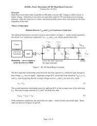
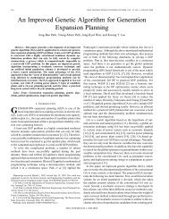
Re-examining the capacitor current in Figure 9, and re-illustrated in Figure 10, it can be seen that<br />
the amount of charge taken from C when the switch is closed is represented by the dotted area.<br />
2 I<br />
−<br />
in I out<br />
0<br />
Iin − I out<br />
−<br />
I out<br />
DT (1–D)T ΔQ<br />
Figure 10. Capacitor Charge Given Up While Switch is Closed<br />
As D → 1, the width of the dotted area increases to fill almost the entire cycle, and the<br />
maximum peak-to-peak ripple becomes<br />
Iout<br />
• T Iout<br />
ΔV<br />
max = = . (16)<br />
C Cf<br />
The Experiment (Important - to avoid high output voltages, always keep a load attached to<br />
the boost converter output when input power is applied. Use a conventional 120V, 150W<br />
light bulb as your load. Do not exceed 120V on the output.<br />
1. Convert a buck converter to a boost converter, using the circuit shown in Figure 1 of this<br />
document.<br />
2. Double-check that the polarity of your converter’s output capacitor is correct.<br />
3. Locate one of the 150W light bulb test load assemblies. Check the light bulb with an<br />
ohmmeter to make sure it is not burned out.<br />
4. Connect the light bulb test load to your circuit.<br />
5. Connect an oscilloscope Channel #1 to view V GS , and Channel #2 to view V DS . The<br />
ground clip of the Channel #2 probe should not be attached to the circuit, but instead it<br />
should be clipped back onto its own lead in-cable so that it does not dangle.<br />
Page 8 of 11