EE462L, Power Electronics, DC-DC Boost Converter Version ... - ECS
EE462L, Power Electronics, DC-DC Boost Converter Version ... - ECS
EE462L, Power Electronics, DC-DC Boost Converter Version ... - ECS

Create successful ePaper yourself
Turn your PDF publications into a flip-book with our unique Google optimized e-Paper software.
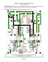
<strong>EE462L</strong>, <strong>Power</strong> <strong>Electronics</strong>, <strong>DC</strong>-<strong>DC</strong> <strong>Boost</strong> <strong>Converter</strong><br />
<strong>Version</strong> Oct. 3, 2011<br />
Lboundary<br />
VinD<br />
= . (9)<br />
2Iin<br />
f<br />
Because the maximum value of D is 1, then<br />
Vin<br />
L > . (10)<br />
2Iin<br />
f<br />
will guarantee continuous conduction for all D. Note in (9) and (10) that continuous conduction<br />
can be achieved more easily when I out and f are large.<br />
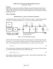
Discontinuous Conduction<br />
At low load, the converter may slip into the discontinuous conduction mode. Referring back to<br />
Figure 2b, this occurs when the inductor current coasts to zero. At that moment, the capacitor<br />
attempts to reverse i L and “backfeed” the inductor, but the diode prevents current reversal. Thus,<br />
the diode opens, and the circuit assumes the topology shown in Figure 6 until the switch closes<br />
again. During this third state, all load power is provided by the capacitor.<br />
+ 0 –<br />
0<br />
I out<br />
V in<br />
L<br />
C<br />
+<br />
V out<br />
–<br />
Figure 6. Third State for Discontinuous Conduction<br />
Once discontinuous, the voltage across the inductor is zero. The corresponding voltage<br />
waveform is shown in Figure 7.<br />
V in<br />
Discontinuous<br />
Vin − V out<br />
0<br />
Figure 7. Inductor Voltage in Discontinuous Conduction<br />
Page 4 of 11