EE462L, Power Electronics, DC-DC Boost Converter Version ... - ECS
EE462L, Power Electronics, DC-DC Boost Converter Version ... - ECS
EE462L, Power Electronics, DC-DC Boost Converter Version ... - ECS

Create successful ePaper yourself
Turn your PDF publications into a flip-book with our unique Google optimized e-Paper software.
<strong>EE462L</strong>, <strong>Power</strong> <strong>Electronics</strong>, <strong>DC</strong>-<strong>DC</strong> <strong>Boost</strong> <strong>Converter</strong><br />
<strong>Version</strong> Oct. 3, 2011<br />
diL<br />
dt<br />
vL<br />
Vin<br />
−Vout<br />
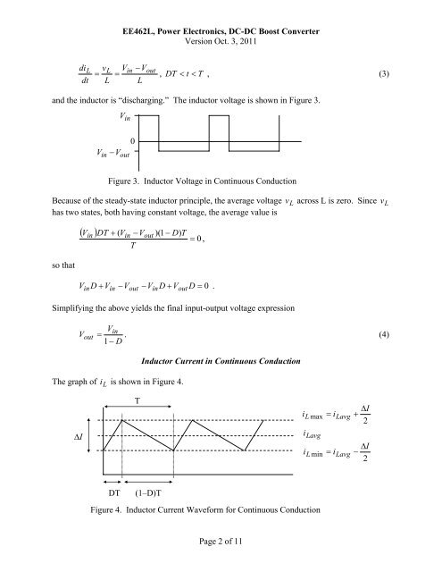
= = , DT < t < T , (3)<br />
L L<br />
and the inductor is “discharging.” The inductor voltage is shown in Figure 3.<br />
V in<br />
0<br />
Vin − V out<br />
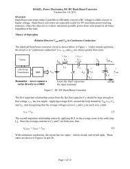
Figure 3. Inductor Voltage in Continuous Conduction<br />
Because of the steady-state inductor principle, the average voltage v L across L is zero. Since v L<br />
has two states, both having constant voltage, the average value is<br />
( V )<br />
in DT + ( Vin<br />
−Vout<br />
T<br />
)(1 − D)<br />
T<br />
= 0 ,<br />
so that<br />
Vin D + Vin<br />
−Vout<br />
−VinD<br />
+ Vout<br />
D = 0 .<br />
Simplifying the above yields the final input-output voltage expression<br />
Vout<br />
Vin<br />
= . (4)<br />
1 − D<br />
The graph of i L is shown in Figure 4.<br />
Inductor Current in Continuous Conduction<br />
Δ I<br />
T<br />
i<br />
L max<br />
i Lavg<br />
i<br />
L min<br />
= i<br />
= i<br />
Lavg<br />
Lavg<br />
ΔI<br />
+<br />
2<br />
ΔI<br />
−<br />
2<br />
DT<br />
(1–D)T<br />
Figure 4. Inductor Current Waveform for Continuous Conduction<br />
Page 2 of 11