Rotary Seals - Dilanda.it
Rotary Seals - Dilanda.it
Rotary Seals - Dilanda.it

You also want an ePaper? Increase the reach of your titles
YUMPU automatically turns print PDFs into web optimized ePapers that Google loves.
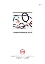
GAMMA Seal<br />
Figure 64<br />
70<br />
TBP/RB<br />
RB 55<br />
Case<br />
Sealing<br />
element<br />
GAMMA seal types<br />
TBR/9RB<br />
Manufacture materials<br />
The sealing member is moulded and is normally made of<br />
N<strong>it</strong>rile rubber w<strong>it</strong>h a hardness of 75±5 IRHD. Other<br />
compounds can be supplied on request. The case is<br />
stamped of cold-rolled steel sheet. In order to ensure a<br />
good seal and a tight grip on the shaft, the inside diameter<br />
is machined to dimensions which ensure a su<strong>it</strong>able press f<strong>it</strong>.<br />
The tolerances for the inside diameter of the case are given<br />
in Table XLVI. The case is normally zinc plated. The case can<br />
also be made out ot other materials, e.g. in stainless steel.<br />
Installation design<br />
GAMMA seal type TBP should normally be installed as<br />
shown in Figure 67, i.e. w<strong>it</strong>h the seal located in the medium<br />
which is to seal against. As shown in Figure 71 the counter<br />
face for type TBR against which the sealing lip works<br />
should be designed w<strong>it</strong>h a groove for the case extension in<br />
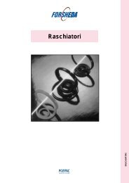
order to create the clearance seal. For vertical shafts a<br />
design in accordance w<strong>it</strong>h Figure 66 is preferred, which<br />
effectively will reject impur<strong>it</strong>ies and liquid splatter. Shaft<br />
tolerance ISO h9 provides a su<strong>it</strong>able press f<strong>it</strong>. The shaft<br />
tolerances normally used for ball and roller bearings,<br />
ISO g6 to n6, can also be used. The seal does not require<br />
any other axial fixation other than that which is obtained<br />
by the press f<strong>it</strong> between the case and the shaft.<br />
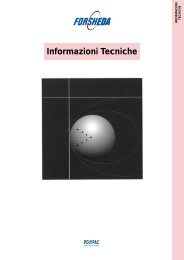
Power loss, W<br />
60<br />
50<br />
40<br />
30<br />
20<br />
TBP000550<br />
RB 55<br />
TBP000200<br />
RB 20<br />
10<br />
0<br />
0 1 2 3 4 5 6 7 8 9 10 11 12 13 14 15 16 17 1819 20<br />
Speed, m/s<br />
RB 55<br />
Figure 65<br />
Power loss as a function of peripheral speed<br />
(Counterface 1.5-2 μm Ra not lubricated seal)<br />
Figure 66<br />
Vertical installation<br />
However, providing a shoulder or a circlip to pos<strong>it</strong>ion the<br />
ring may facil<strong>it</strong>ate f<strong>it</strong>ting. The installation dimensions are<br />
given in the dimension table.<br />
Latest information available at www.busakshamban.com<br />
Ed<strong>it</strong>ion April 2006<br />
169