- Page 1 and 2: Rotary Seals Deutsch Your Partner f
- Page 3 and 4: Rotary Seal General description ...
- Page 5 and 6: Rotary Seal n GENERAL DESCRIPTION T
- Page 7 and 8: Rotary Seal V—Rings Family V—Ri
- Page 9 and 10: Rotary Seal PTFE Rotary Shaft seals
- Page 11 and 12: Rotary Seal n Introduction Rotating
- Page 13 and 14: Rotary Seal Shaft run out and eccen
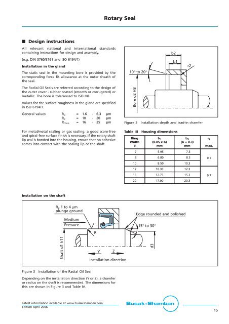
- Page 15: Rotary Seal n Quality criteria The
- Page 19 and 20: Rotary Seal Surface finish In order
- Page 21 and 22: Radial Oil Seal Sealing element Mat
- Page 23 and 24: Radial Oil Seal Fluorinated Rubber
- Page 25 and 26: Radial Oil Seal Metal case The prin
- Page 27 and 28: Radial Oil Seal Peripheral speed an
- Page 29 and 30: Radial Oil Seal n Shaft and housing
- Page 31 and 32: Radial Oil Seal n Standard types of
- Page 33 and 34: Radial Oil Seal Table VI Materials
- Page 35 and 36: Radial Oil Seal Dimension Part no.
- Page 37 and 38: Radial Oil Seal Dimension Part no.
- Page 39 and 40: Radial Oil Seal Dimension Part no.
- Page 41 and 42: Radial Oil Seal Dimension Part no.
- Page 43 and 44: Radial Oil Seal Dimension Part no.
- Page 45 and 46: Radial Oil Seal Dimension Part no.
- Page 47 and 48: Radial Oil Seal Dimension Part no.
- Page 49 and 50: Radial Oil Seal Dimension Part no.
- Page 51 and 52: Radial Oil Seal Dimension Part no.
- Page 53 and 54: Radial Oil Seal Dimension Part no.
- Page 55 and 56: Radial Oil Seal n Busak+Shamban typ
- Page 57 and 58: Radial Oil Seal Dimension Part no.
- Page 59 and 60: Radial Oil Seal Dimension Part no.
- Page 61 and 62: Radial Oil Seal Dimension Part no.
- Page 63 and 64: Radial Oil Seal Dimension Part no.
- Page 65 and 66: Radial Oil Seal Dimension Part no.
- Page 67 and 68:
Radial Oil Seal Ordering example oi
- Page 69 and 70:
Radial Oil Seal Table X Materials S
- Page 71 and 72:
Radial Oil Seal Dimension Part no.
- Page 73 and 74:
Radial Oil Seal Dimension Part no.
- Page 75 and 76:
Radial Oil Seal n Busak+Shamban typ
- Page 77 and 78:
Radial Oil Seal Dimension Part no.
- Page 79 and 80:
Radial Oil Seal Dimension Part no.
- Page 81 and 82:
Radial Oil Seal n Busak+Shamban typ
- Page 83 and 84:
Radial Oil Seal Dimension Part no.
- Page 85 and 86:
Radial Oil Seal Dimension Part no.
- Page 87 and 88:
Radial Oil Seal Dimension Part no.
- Page 89 and 90:
Radial Oil Seal n Busak+Shamban typ
- Page 91 and 92:
Radial Oil Seal Dimension Part no.
- Page 93 and 94:
Radial Oil Seal n Special types of
- Page 95 and 96:
Radial Oil Seal Table XVIII Materia
- Page 97 and 98:
Radial Oil Seal Table XIX Materials
- Page 99 and 100:
Radial Oil Seal Ordering example oi
- Page 101 and 102:
Radial Oil Seal Table XXI Materials
- Page 103 and 104:
Radial Oil Seal n STEFA type 12CC -
- Page 105 and 106:
Radial Oil Seal n Busak+Shamban typ
- Page 107 and 108:
Radial Oil Seal Dimension Part no.
- Page 109 and 110:
Radial Oil Seal n Busak+Shamban typ
- Page 111 and 112:
Radial Oil Seal Dimension Part no.
- Page 113 and 114:
Radial Oil Seal n Rotary and axial
- Page 115 and 116:
Radial Oil Seal n Product descripti
- Page 117 and 118:
Radial Oil Seal n STEFA standard AP
- Page 119 and 120:
Radial Oil Seal n STEFA 1B/APJ and
- Page 121 and 122:
End Cover n END COVER General descr
- Page 123 and 124:
End Cover Bore D H8 Width B Chamfer
- Page 125 and 126:
End Cover n Busak+Shamban type YJ 3
- Page 127 and 128:
Shaft Repair Kit n SHAFT REPAIR KIT
- Page 129 and 130:
Shaft Repair Kit n Installation rec
- Page 131 and 132:
Shaft Repair Kit n Installation rec
- Page 133 and 134:
Shaft Repair Kit Shaft diameter imp
- Page 135 and 136:
Shaft Repair Kit Shaft diameter imp
- Page 137 and 138:
Cassette Seal n System 3000 n Syste
- Page 139 and 140:
Cassette Seal ID d 1 OD Width Syste
- Page 141 and 142:
Cassette Seal Temperature limits fo
- Page 143 and 144:
Cassette Seal Shaft run out Shaft r
- Page 145 and 146:
Cassette Seal System 5000 The Syste
- Page 147 and 148:
V—Ring 70 65 60 d=190 V-Rings in
- Page 149 and 150:
V—Ring recommended to arrange an
- Page 151 and 152:
V—Ring The power losses are influ
- Page 153 and 154:
V—Ring n Dimension table - V—Ri
- Page 155 and 156:
V—Ring For shaft diameter d 1 Ins
- Page 157 and 158:
V—Ring n Dimension table - V—Ri
- Page 159 and 160:
V—Ring n Dimension table - V—Ri
- Page 161 and 162:
V—Ring Ordering example V—Ring,
- Page 163 and 164:
V—Ring For shaft diameter d 1 Ins
- Page 165 and 166:
V—Ring For shaft diameter d 1 Ins
- Page 167 and 168:
V—Ring n Dimension table - V—Ri
- Page 169 and 170:
V—Ring V—Ring AX larger than 20
- Page 171 and 172:
GAMMA Seal Figure 64 70 TBP/RB RB 5
- Page 173 and 174:
GAMMA Seal b b ø d + 0.5 ø d Figu
- Page 175 and 176:
GAMMA Seal Table XLVII Materials St
- Page 177 and 178:
GAMMA Seal n GAMMA-seal type TBR/9R
- Page 179 and 180:
Axial Shaft Seal n AXIAL SHAFT SEAL
- Page 181 and 182:
Axial Shaft Seal n Applications Fie
- Page 183 and 184:
Axial Shaft Seal Design instruction
- Page 185 and 186:
Axial Shaft Seal Shaft Dimensions M
- Page 187 and 188:
Axial Shaft Seal Ordering example A
- Page 189 and 190:
Axial Shaft Seal Shaft Dimensions M
- Page 191 and 192:
Turcon ® Roto Glyd Ring ® n TURCO
- Page 193 and 194:
Turcon ® Roto Glyd Ring ® Table L
- Page 195 and 196:
Turcon ® Roto Glyd Ring ® 30 10 -
- Page 197 and 198:
Turcon ® Roto Glyd Ring ® Materia
- Page 199 and 200:
Turcon ® Roto Glyd Ring ® Table L
- Page 201 and 202:
Turcon ® Roto Glyd Ring ® Orderin
- Page 203 and 204:
Turcon ® Roto Glyd Ring ® Table L
- Page 205 and 206:
Turcon ® Roto Glyd Ring ® Orderin
- Page 207 and 208:
Turcon ® Roto Variseal ® n TURCON
- Page 209 and 210:
Turcon ® Roto Variseal ® blend ra
- Page 211 and 212:
Turcon ® Roto Variseal ® n Instal
- Page 213 and 214:
Latest information available at www
- Page 215 and 216:
Latest information available at www
- Page 217 and 218:
Latest information available at www
- Page 220:
For further information: Europe Tel