Gas Burners RS 70/M - Power Equipment Company
Gas Burners RS 70/M - Power Equipment Company
Gas Burners RS 70/M - Power Equipment Company

You also want an ePaper? Increase the reach of your titles
YUMPU automatically turns print PDFs into web optimized ePapers that Google loves.
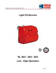
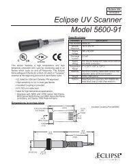
(A)<br />
inch A B C<br />
<strong>RS</strong> <strong>70</strong>/M<br />
<strong>RS</strong> 100/M<br />
<strong>RS</strong> 130/M<br />
7 9 /32“<br />
7 9 /32“<br />
7 21 /32“<br />
1013 /16“ - 12 25 /32“<br />
10 13 /16“ - 12 25 /32“<br />
10 13 /16“ - 12 25 /32“<br />
1/2 W<br />
1/2 W<br />
1/2 W<br />
D455<br />
INSTALLATION<br />
BOILER PLATE (A)<br />
Drill the combustion chamber mounting plate as shown<br />
in (A). The position of the threaded holes can be marked<br />
using the burner head gasket supplied with the burner.<br />
BLAST TUBE LENGTH (B)<br />
The length of the blast tube must be selected according<br />
to the indications provided by the manufacturer of the<br />
boiler, it must be greater than the thickness of the boiler<br />
door complete with its insulation. The length available, L<br />
(inches), is as follows:<br />
Blast tube 12) <strong>RS</strong> <strong>70</strong>/M <strong>RS</strong> 100/M <strong>RS</strong> 130/M<br />
• short 9 27 /32“ 9 27 /32“ 11 1 /32“<br />
• long (with kit) 15 5 /32“ 15 5 /32“ 16 11 /32“<br />
For boilers with front flue passes 15) or flame inversion<br />
chambers, protective insulation material 13), must be<br />
inserted between the boiler refractory 14) and the blast<br />
tube 12).<br />
This protective insulation must not compromise the<br />
extraction of the blast tube.<br />
For boilers having a water-cooled front, the insulation<br />
13)-14) is not required unless it is required by the boiler<br />
manufacturer.<br />
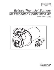
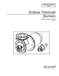
(B)<br />
Ignition<br />
pilot<br />
Probe<br />
D2404<br />
SECURING THE BURNER TO THE BOILER (B)<br />
Before securing the burner to the boiler, check through<br />
the blast tube opening to make sure that the flame sensor<br />
probe (flame rod) is correctly set in position, as<br />
shown in (C).<br />
Now detach the combustion head from the burner, fig.<br />
(B):<br />
- loosen the four screws 3) and remove the cover 1);<br />
- disengage the swivel joint 7) from the graduated sector<br />
8);<br />
- remove the screws 2) from the slide bars 5);<br />
- remove the two screws 4) and pull the burner back on<br />
slide bars 5) by about 4”;<br />
- disconnect the wires from the flame rod and the electrode<br />
and then pull the burner completely off the slide<br />
bars.<br />
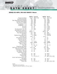
COMBUSTION HEAD CALIBRATION<br />
At this point check, for model <strong>RS</strong> 130/M, whether the<br />
maximum delivery of the burner at high fire operation is<br />
contained in area A or in area B of the firing rate. See<br />
page 5.<br />
If it is in area A then no operation is required.<br />
If, on the other hand, it is in area B:<br />
- unscrew the screws 1)(D) and disassemble the blast<br />
tube 2);<br />
- move the fixing of the rod 3)(D) from position A to<br />
position B, thereby causing the shutter 4) to retract;<br />
- now refit the blast tube 2)(D) and the screws 1).<br />
Once this operation has been carried out (if it was<br />
required), secure the flange 11)(B) to the boiler plate,<br />
inserting the gasket 9)(B). Use the 4 screws, also supplied<br />
with the unit, after first protecting the thread with an<br />
anti-locking product. The seal between burner and boiler<br />
must be airtight.<br />
If you noticed any irregularities in the positions of the<br />
flame rod or ignition electrode during the check mentioned<br />
above, remove screw 1)(E), extract the internal<br />
part 2)(E) of the head and set up the two components<br />
correctly.<br />
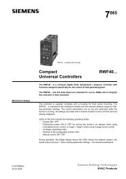
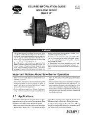
(C)<br />
Electrode<br />
D2391<br />
(D)<br />
D738<br />
(E)<br />
(F)<br />
MB - Burner terminal strip<br />
D2398<br />
D2317<br />
IGNITION PILOT ADJUSTMENT<br />
Place the pilot and electrode as shown in fig. (C).<br />
The pilot works correctly at pressures ranging from 5 -<br />
12” WC.<br />
Important<br />
To set the pilot without main burner operaton, proceed<br />
as follows:<br />
- Move the jumper from terminals "30-V11" to terminals<br />
"30-VP", as given in fig. (F), this way the main valve is<br />
cut out.<br />
- With the burner in the manual position, hold the air<br />
damper in the minimum position and make the setting.<br />
- When the setting is correct, replace the jumper on “30-<br />
V11”.<br />
7