Gas Burners RS 70/M - Power Equipment Company
Gas Burners RS 70/M - Power Equipment Company
Gas Burners RS 70/M - Power Equipment Company

Create successful ePaper yourself
Turn your PDF publications into a flip-book with our unique Google optimized e-Paper software.
<strong>RS</strong> <strong>70</strong>/M<br />
∆p (“WC)<br />
MBtu/hr kW 1 2<br />
1761 516 1.65 0.08<br />
1952 572 1.89 0.08<br />
2139 627 2.20 0.12<br />
2330 683 2.52 0.12<br />
2518 738 2.87 0.12<br />
2<strong>70</strong>9 794 3.27 0.16<br />
2897 849 3.66 0.16<br />
3084 904 4.06 0.16<br />
<strong>RS</strong> 100/M<br />
∆p (“WC)<br />
MBtu/hr kW 1 2<br />
2631 771 1.46 0.16<br />
2880 844 1.65 0.16<br />
3125 916 1.97 0.20<br />
3371 988 2.28 0.20<br />
3617 1060 2.56 0.24<br />
3862 1132 2.87 0.28<br />
4108 1204 3.27 0.31<br />
4405 1291 3.66 0.31<br />
<strong>RS</strong> 130/M<br />
∆p (“WC)<br />
MBtu/hr kW 1 2<br />
3521 1032 1.50 0.39<br />
3825 1121 1.77 0.43<br />
4129 1210 2.01 0.51<br />
4432 1299 2.28 0.59<br />
4736 1388 2.56 0.67<br />
5036 1476 2.83 0.71<br />
5340 1565 3.11 0.75<br />
5545 1625 3.20 0.77<br />
(A)<br />
GAS PRESSURE<br />
The adjacent tables show minimum pressure losses<br />
along the gas supply line depending on the maximum<br />
burner output operation with natural gas.<br />
Column 1<br />
Pressure loss at combustion head.<br />
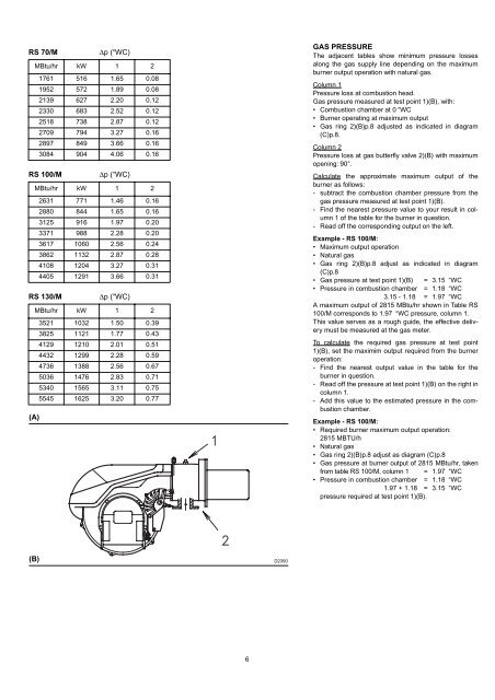
<strong>Gas</strong> pressure measured at test point 1)(B), with:<br />
• Combustion chamber at 0 “WC<br />
• Burner operating at maximum output<br />
• <strong>Gas</strong> ring 2)(B)p.8 adjusted as indicated in diagram<br />
(C)p.8.<br />
Column 2<br />
Pressure loss at gas butterfly valve 2)(B) with maximum<br />
opening: 90°.<br />
Calculate the approximate maximum output of the<br />
burner as follows:<br />
- subtract the combustion chamber pressure from the<br />
gas pressure measured at test point 1)(B).<br />
- Find the nearest pressure value to your result in column<br />
1 of the table for the burner in question.<br />
- Read off the corresponding output on the left.<br />
Example - <strong>RS</strong> 100/M:<br />
• Maximum output operation<br />
• Natural gas<br />
• <strong>Gas</strong> ring 2)(B)p.8 adjust as indicated in diagram<br />
(C)p.8<br />
• <strong>Gas</strong> pressure at test point 1)(B) = 3.15 “WC<br />
• Pressure in combustion chamber = 1.18 “WC<br />
3.15 - 1.18 = 1.97 “WC<br />
A maximum output of 2815 MBtu/hr shown in Table <strong>RS</strong><br />
100/M corresponds to 1.97 “WC pressure, column 1.<br />
This value serves as a rough guide, the effective delivery<br />
must be measured at the gas meter.<br />
To calculate the required gas pressure at test point<br />
1)(B), set the maximim output required from the burner<br />
operation:<br />
- Find the nearest output value in the table for the<br />
burner in question.<br />
- Read off the pressure at test point 1)(B) on the right in<br />
column 1.<br />
- Add this value to the estimated pressure in the combustion<br />
chamber.<br />
Example - <strong>RS</strong> 100/M:<br />
• Required burner maximum output operation:<br />
2815 MBTU/h<br />
• Natural gas<br />
• <strong>Gas</strong> ring 2)(B)p.8 adjust as diagram (C)p.8<br />
• <strong>Gas</strong> pressure at burner output of 2815 MBtu/hr, taken<br />
from table <strong>RS</strong> 100/M, column 1 = 1.97 “WC<br />
• Pressure in combustion chamber = 1.18 “WC<br />
1.97 + 1.18 = 3.15 “WC<br />
pressure required at test point 1)(B).<br />
(B)<br />
D2390<br />
6