Gas Burners RS 70/M - Power Equipment Company
Gas Burners RS 70/M - Power Equipment Company
Gas Burners RS 70/M - Power Equipment Company

You also want an ePaper? Increase the reach of your titles
YUMPU automatically turns print PDFs into web optimized ePapers that Google loves.
Full Modulation<br />
BURNER OPERATION<br />
BURNER STARTING<br />
• Load control close.<br />
Fan motor starts.<br />
• Servomotor starts:<br />
130° rotation to right, until contact is made on cam<br />
1)(A) page 12.<br />
The air damper is positioned to MAX. output.<br />
• Pre-purge stage with air delivery at MAX. output.<br />
• After pre-purge stage, servomotor rotates to left up to<br />
the angle set on cam 3)(A) page 12 for MIN. output.<br />
• The air damper and the gas butterfly are positioned to<br />
MIN. output.<br />
• Ignition electrode strikes a spark.<br />
• Pilot valve opens. The pilot flame is ignited.<br />
• After about 12 s the main flame ignites and starting<br />
cycle ends.<br />
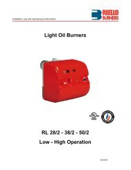
(A)<br />
Low - High<br />
D2273<br />
STEADY STATE OPERATION<br />
At the end of the starting cycle, the servomotor control<br />
then passes to the load control for boiler pressure or<br />
temperature.<br />
(The LFL control box continues, however, to check that<br />
the flame is present and that the air pressure switch is in<br />
the correct position.)<br />
• If the temperature or pressure is low, the burner progressively<br />
increases its output to the MAX. value.<br />
• If the temperature or pressure is high, the burner progressively<br />
decreases its output to the MIN. value.<br />
And so on.<br />
• The burner locks out when demand for heat is less<br />
than the heat supplied by the burner at min. output.<br />
Load control opens. The servomotor returns to the 0°<br />
angle limited by contact with cam 2. The air damper<br />
closes completely to reduce thermal dispersion to a<br />
minimum.<br />
Every time output is changed, the servomotor automatically<br />
modifies gas delivery (gas butterfly valve) and air<br />
delivery (fan air damper).<br />
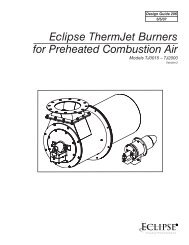
Switching times are given in seconds, in the burner startup<br />
sequence.<br />
LFL 1.335 Series 01<br />
t1<br />
t2<br />
t3<br />
t4<br />
t5<br />
30<br />
2<br />
4<br />
20<br />
optional<br />
t6<br />
t7<br />
t8<br />
t9<br />
optional<br />
12<br />
4<br />
16<br />
(B)<br />
D2274<br />
Legend for the times<br />
t1 Pre-purge time with air damper open<br />
t2 Safety time<br />
t3 Pre-ignition time, short (ignition transformer on<br />
terminal 16)<br />
t4 Interval between start of t2 and release of valve<br />
at terminal 19<br />
t5 Interval between end of t4 and release of load<br />
controller or valve at terminal 20<br />
t5 Running time of air damper into OPEN position<br />
t6 Running time of air damper into low-flame position<br />
(MIN)<br />
t7 Permissible after-burn time<br />
t8 Interval until OPEN command for the air damper<br />
is given<br />
t9 Running time of pilot<br />
FIRING FAILURE<br />
If the burner does not fire, it locks out within 2.5 seconds<br />
from opening the pilot valve and then within 5 seconds<br />
from opening the main valves.<br />
BURNER FLAME GOES OUT DURING OPERATION<br />
If the flame should accidentally go out during operation,<br />
the burner will lock out within 1s.<br />
19