Gas Burners RS 70/M - Power Equipment Company
Gas Burners RS 70/M - Power Equipment Company
Gas Burners RS 70/M - Power Equipment Company

You also want an ePaper? Increase the reach of your titles
YUMPU automatically turns print PDFs into web optimized ePapers that Google loves.
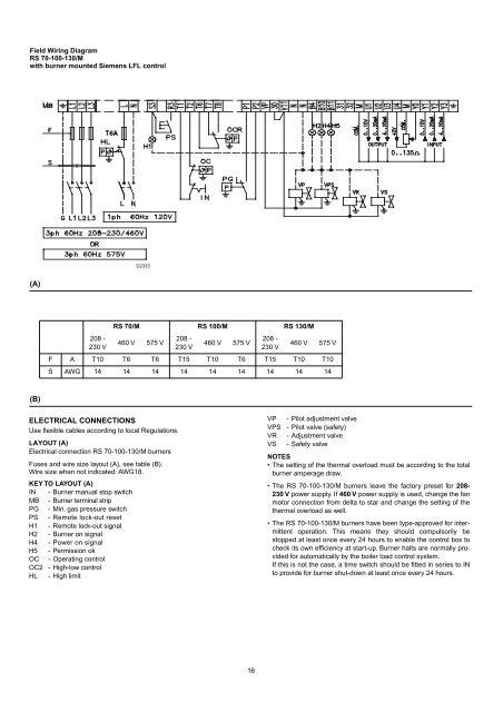
Field Wiring Diagram<br />
<strong>RS</strong> <strong>70</strong>-100-130/M<br />
with burner mounted Siemens LFL control<br />
D2333<br />
(A)<br />
208 -<br />
230 V<br />
<strong>RS</strong> <strong>70</strong>/M <strong>RS</strong> 100/M <strong>RS</strong> 130/M<br />
460 V 575 V<br />
208 -<br />
230 V<br />
460 V 575 V<br />
208 -<br />
230 V<br />
460 V 575 V<br />
F A T10 T6 T6 T15 T10 T6 T15 T10 T10<br />
S AWG 14 14 14 14 14 14 14 14 14<br />
(B)<br />
ELECTRICAL CONNECTIONS<br />
Use flexible cables according to local Regulations.<br />
LAYOUT (A)<br />
Electrical connection <strong>RS</strong> <strong>70</strong>-100-130/M burners<br />
Fuses and wire size layout (A), see table (B).<br />
Wire size when not indicated: AWG18.<br />
KEY TO LAYOUT (A)<br />
IN - Burner manual stop switch<br />
MB - Burner terminal strip<br />
PG - Min. gas pressure switch<br />
PS - Remote lock-out reset<br />
H1 - Remote lock-out signal<br />
H2 - Burner on signal<br />
H4 - <strong>Power</strong> on signal<br />
H5 - Permission ok<br />
OC - Operating control<br />
OC2 - High-low control<br />
HL - High limit<br />
VP - Pilot adjustment valve<br />
VPS - Pilot valve (safety)<br />
VR - Adjustment valve<br />
VS - Safety valve<br />
NOTES<br />
• The setting of the thermal overload must be according to the total<br />
burner amperage draw.<br />
• The <strong>RS</strong> <strong>70</strong>-100-130/M burners leave the factory preset for 208-<br />
230 V power supply. If 460 V power supply is used, change the fan<br />
motor connection from delta to star and change the setting of the<br />
thermal overload as well.<br />
• The <strong>RS</strong> <strong>70</strong>-100-130/M burners have been type-approved for intermittent<br />
operation. This means they should compulsorily be<br />
stopped at least once every 24 hours to enable the control box to<br />
check its own efficiency at start-up. Burner halts are normally provided<br />
for automatically by the boiler load control system.<br />
If this is not the case, a time switch should be fitted in series to IN<br />
to provide for burner shut-down at least once every 24 hours.<br />
16