Gas Burners RS 70/M - Power Equipment Company
Gas Burners RS 70/M - Power Equipment Company
Gas Burners RS 70/M - Power Equipment Company

You also want an ePaper? Increase the reach of your titles
YUMPU automatically turns print PDFs into web optimized ePapers that Google loves.
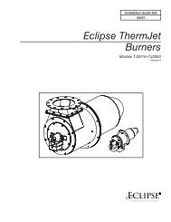
FLAME INSPECTION WINDOW<br />
(A)<br />
OPENING THE BURNER<br />
D<strong>70</strong>9<br />
MAINTENANCE<br />
Combustion<br />
The optimum calibration of the burner requires an analysis<br />
of the flue gases. Significant differences with respect<br />
to the previous measurements indicate the points where<br />
more care should be exercised during maintenance.<br />
<strong>Gas</strong> leaks<br />
Make sure that there are no gas leaks on the pipework<br />
between the gas meter and the burner.<br />
Flame inspection window<br />
Clean the flame inspection window (A).<br />
Combustion head<br />
Open the burner and make sure that all components of<br />
the combustion head are in good condition, not<br />
deformed by the high temperatures, free of impurities<br />
from the surroundings and correctly positioned. If in<br />
doubt, disassemble the elbow fitting 5)(B).<br />
Servomotor<br />
Disengage the cam 4)(D)p. 12 from the servomotor and<br />
turn it backwards and forwards by hand to make sure it<br />
moves freely.<br />
Burner<br />
Check for excess wear or loose screws in the mechanisms<br />
controlling the air damper and the gas butterfly<br />
valve. Also make sure that the screws securing the electrical<br />
leads in the burner terminal strip are fully tightened.<br />
Clean the outside of the burner, taking special care with<br />
the swivel joints and cam.<br />
Combustion<br />
Adjust the burner if the combustion values found at the<br />
beginning of the operation do not comply with the regulations<br />
in force, or do not correspond to good combustion.<br />
Record the new combustion values; they will be<br />
useful for subsequent controls.<br />
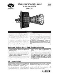
(B)<br />
D2402<br />
TO OPEN THE BURNER (B):<br />
- Switch off the electrical power.<br />
- Loosen screws 1) and withdraw cover 2).<br />
- Disengage the swivel joint 7) from the graduated sector<br />
8).<br />
- Fit the two extensions onto the slide bars 4).<br />
- Remove screws 3), and pull the burner back by about<br />
4” on the slide bars 4). Disconnect the probe and<br />
electrode leads and then pull the burner fully back.<br />
Now extract the gas distributor 5) after having removed<br />
the screw 6) and disconnecting the pilot gas line.<br />
TO CLOSE THE BURNER (B):<br />
- Push the burner until it is about 4” from the sleeve.<br />
- Re-connect the leads and slide in the burner until it<br />
comes to a stop.<br />
- Refit screws 3), and pull the probe and electrode<br />
leads gently out until they are slightly stretched.<br />
- Re-couple the swivel joint 7) to the graduated sector<br />
8).<br />
- Remove the two extensions from the slide bars 4).<br />
- Connect the pilot gas line.<br />
14