Manual THERA-Trainer balo
Manual THERA-Trainer balo
Manual THERA-Trainer balo

Create successful ePaper yourself
Turn your PDF publications into a flip-book with our unique Google optimized e-Paper software.
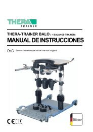
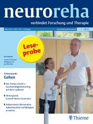
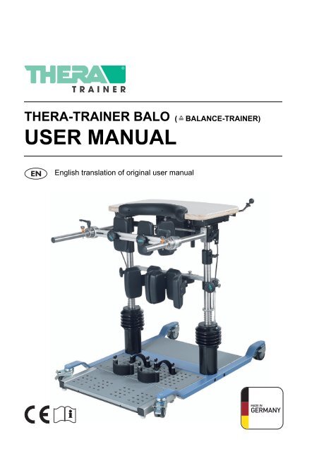
<strong>THERA</strong>-TRAINER BALO<br />
USER MANUAL<br />
( BALANCE-TRAINER)<br />
English translation of original user manual
<strong>THERA</strong>-TRAINER BALO<br />
USER MANUAL<br />
Congratulations!<br />
Opting for a <strong>THERA</strong>-<strong>Trainer</strong> was a great choice. This innovative movement exerciser offers top performance<br />
„Made in Germany“.<br />
This user manual will help you get to know your <strong>THERA</strong>-<strong>Trainer</strong> better. It will safely guide you through all<br />
functions and control options and provide you with tips and information on how to use your new exerciser<br />
best.<br />
Before starting the unit for the first time, please read and observe chapter 2 “Safety and dangers”.<br />
Should you have any questions or suggestions, your local specialist dealer will be happy to help.<br />
Have fun and get moving with your <strong>THERA</strong>-<strong>Trainer</strong>.<br />
2 Art. no.: A002-565<br />
Version: 04/2013
<strong>THERA</strong>-TRAINER BALO<br />
USER MANUAL<br />
1 USER GUIDE . . . . . . . . . . . . . . . . . . . . . . . . . . . . . . . . . . . . . . . . . . . . . . . . . . . . . . . . . . . . . . . . . . 4<br />
1.1 Warning notices . . . . . . . . . . . . . . . . . . . . . . . . . . . . . . . . . . . . . . . . . . . . . . . . . . . . . . . . . . . . . . . . 4<br />
1.2 Notes . . . . . . . . . . . . . . . . . . . . . . . . . . . . . . . . . . . . . . . . . . . . . . . . . . . . . . . . . . . . . . . . . . . . . . . . 4<br />
1.3 Symbols in the user manual . . . . . . . . . . . . . . . . . . . . . . . . . . . . . . . . . . . . . . . . . . . . . . . . . . . . . . . 4<br />
1.4 Symbols on the product . . . . . . . . . . . . . . . . . . . . . . . . . . . . . . . . . . . . . . . . . . . . . . . . . . . . . . . . . . 5<br />
2 SAFETY AND DANGERS . . . . . . . . . . . . . . . . . . . . . . . . . . . . . . . . . . . . . . . . . . . . . . . . . . . . . . . . 6<br />
3 INTENDED USE. . . . . . . . . . . . . . . . . . . . . . . . . . . . . . . . . . . . . . . . . . . . . . . . . . . . . . . . . . . . . . . . 7<br />
3.1 Indications . . . . . . . . . . . . . . . . . . . . . . . . . . . . . . . . . . . . . . . . . . . . . . . . . . . . . . . . . . . . . . . . . . . . 7<br />
3.2 Biocompatibility. . . . . . . . . . . . . . . . . . . . . . . . . . . . . . . . . . . . . . . . . . . . . . . . . . . . . . . . . . . . . . . . . 7<br />
4 FORESEEABLE MISUSE . . . . . . . . . . . . . . . . . . . . . . . . . . . . . . . . . . . . . . . . . . . . . . . . . . . . . . . . 7<br />
4.1 Contraindications . . . . . . . . . . . . . . . . . . . . . . . . . . . . . . . . . . . . . . . . . . . . . . . . . . . . . . . . . . . . . . . 8<br />
4.2 Misuse . . . . . . . . . . . . . . . . . . . . . . . . . . . . . . . . . . . . . . . . . . . . . . . . . . . . . . . . . . . . . . . . . . . . . . . 8<br />
5 SCOPE OF DELIVERY AND DESCRIPTION OF DE-LIVERED EQUIPMENT . . . . . . . . . . . . . . . 9<br />
5.1 Scope of delivery . . . . . . . . . . . . . . . . . . . . . . . . . . . . . . . . . . . . . . . . . . . . . . . . . . . . . . . . . . . . . . . 9<br />
5.2 Basic equipment . . . . . . . . . . . . . . . . . . . . . . . . . . . . . . . . . . . . . . . . . . . . . . . . . . . . . . . . . . . . . . . . 9<br />
5.3 Options . . . . . . . . . . . . . . . . . . . . . . . . . . . . . . . . . . . . . . . . . . . . . . . . . . . . . . . . . . . . . . . . . . . . . . . 9<br />
6 OVERVIEW . . . . . . . . . . . . . . . . . . . . . . . . . . . . . . . . . . . . . . . . . . . . . . . . . . . . . . . . . . . . . . . . . . 10<br />
7 START-UP . . . . . . . . . . . . . . . . . . . . . . . . . . . . . . . . . . . . . . . . . . . . . . . . . . . . . . . . . . . . . . . . . . . 11<br />
7.1 Unpacking. . . . . . . . . . . . . . . . . . . . . . . . . . . . . . . . . . . . . . . . . . . . . . . . . . . . . . . . . . . . . . . . . . . . 11<br />
7.2 Installation of <strong>THERA</strong>-<strong>Trainer</strong> <strong>balo</strong>. . . . . . . . . . . . . . . . . . . . . . . . . . . . . . . . . . . . . . . . . . . . . . . . . 11<br />
7.3 Transport of <strong>THERA</strong>-<strong>Trainer</strong> <strong>balo</strong>. . . . . . . . . . . . . . . . . . . . . . . . . . . . . . . . . . . . . . . . . . . . . . . . . . 13<br />
8 OPERATION . . . . . . . . . . . . . . . . . . . . . . . . . . . . . . . . . . . . . . . . . . . . . . . . . . . . . . . . . . . . . . . . . 14<br />
8.1 Preparation for training . . . . . . . . . . . . . . . . . . . . . . . . . . . . . . . . . . . . . . . . . . . . . . . . . . . . . . . . . . 14<br />
8.2 Safety devices . . . . . . . . . . . . . . . . . . . . . . . . . . . . . . . . . . . . . . . . . . . . . . . . . . . . . . . . . . . . . . . . 24<br />
9 CONTROL . . . . . . . . . . . . . . . . . . . . . . . . . . . . . . . . . . . . . . . . . . . . . . . . . . . . . . . . . . . . . . . . . . . 25<br />
9.1 Control elements . . . . . . . . . . . . . . . . . . . . . . . . . . . . . . . . . . . . . . . . . . . . . . . . . . . . . . . . . . . . . . 25<br />
9.2 Electric lift . . . . . . . . . . . . . . . . . . . . . . . . . . . . . . . . . . . . . . . . . . . . . . . . . . . . . . . . . . . . . . . . . . . . 25<br />
9.3 Lifting and lowering without electric lift . . . . . . . . . . . . . . . . . . . . . . . . . . . . . . . . . . . . . . . . . . . . . . 28<br />
9.4 Starting up the control and display unit . . . . . . . . . . . . . . . . . . . . . . . . . . . . . . . . . . . . . . . . . . . . . 29<br />
10 CLEANING AND DISINFECTION . . . . . . . . . . . . . . . . . . . . . . . . . . . . . . . . . . . . . . . . . . . . . . . . . 31<br />
11 MAINTENANCE AND REPAIR . . . . . . . . . . . . . . . . . . . . . . . . . . . . . . . . . . . . . . . . . . . . . . . . . . . 32<br />
11.1 Replacing the balance unit . . . . . . . . . . . . . . . . . . . . . . . . . . . . . . . . . . . . . . . . . . . . . . . . . . . . . . . 32<br />
11.2 Replacing the patient belt with leg straps and bottom enlarged . . . . . . . . . . . . . . . . . . . . . . . . . . . 32<br />
11.3 Replacing the fuse . . . . . . . . . . . . . . . . . . . . . . . . . . . . . . . . . . . . . . . . . . . . . . . . . . . . . . . . . . . . . 32<br />
11.4 Further use . . . . . . . . . . . . . . . . . . . . . . . . . . . . . . . . . . . . . . . . . . . . . . . . . . . . . . . . . . . . . . . . . . . 32<br />
12 TECHNICAL DATA . . . . . . . . . . . . . . . . . . . . . . . . . . . . . . . . . . . . . . . . . . . . . . . . . . . . . . . . . . . . 33<br />
13 STANDARDS AND LAWS. . . . . . . . . . . . . . . . . . . . . . . . . . . . . . . . . . . . . . . . . . . . . . . . . . . . . . .33<br />
14 DISPOSAL . . . . . . . . . . . . . . . . . . . . . . . . . . . . . . . . . . . . . . . . . . . . . . . . . . . . . . . . . . . . . . . . . . . 33<br />
15 NOTES ON ELECTROMAGNETIC COMPATIBILITY . . . . . . . . . . . . . . . . . . . . . . . . . . . . . . . . . 34<br />
15.1 Lines, line lengths and accessories . . . . . . . . . . . . . . . . . . . . . . . . . . . . . . . . . . . . . . . . . . . . . . . . 34<br />
15.2 Warning notice regarding installation . . . . . . . . . . . . . . . . . . . . . . . . . . . . . . . . . . . . . . . . . . . . . . . 34<br />
15.3 Level of conformity . . . . . . . . . . . . . . . . . . . . . . . . . . . . . . . . . . . . . . . . . . . . . . . . . . . . . . . . . . . . . 34<br />
15.4 Electromagnetic emission. . . . . . . . . . . . . . . . . . . . . . . . . . . . . . . . . . . . . . . . . . . . . . . . . . . . . . . . 34<br />
15.5 Immunity . . . . . . . . . . . . . . . . . . . . . . . . . . . . . . . . . . . . . . . . . . . . . . . . . . . . . . . . . . . . . . . . . . . . . 35<br />
15.6 Recommended protective distances between portable and mobile HF telecommunication devices<br />
and <strong>THERA</strong>-<strong>Trainer</strong> <strong>balo</strong> . . . . . . . . . . . . . . . . . . . . . . . . . . . . . . . . . . . . . . . . . . . . . . . . . . . . . . . . 37<br />
16 WARRANTY. . . . . . . . . . . . . . . . . . . . . . . . . . . . . . . . . . . . . . . . . . . . . . . . . . . . . . . . . . . . . . . . . . 37<br />
Art. no: A002-565<br />
Version: 04/2013<br />
3
<strong>THERA</strong>-TRAINER BALO<br />
USER MANUAL<br />
1 USER GUIDE<br />
User manual and product are labelled with symbols. The symbols and their<br />
functions make it easier to use the product safely and efficiently.<br />
1.1 Warning notices<br />
Classification of warning notices<br />
There are different types of warning notices indicated by the following signal words<br />
depending on the type of danger:<br />
Caution warns about the risk of material damage.<br />
Warning warns about the risk of physical injury.<br />
Danger warns about the risk of fatal injury.<br />
Structure of warning notices<br />
Type and source of danger!<br />
Action to avoid the danger.<br />
Signal words<br />
1.2 Notes<br />
Note<br />
Information on the efficient use of the product.<br />
1.3 Symbols in the user manual<br />
Instructions<br />
Structure of instructions:<br />
Instruction to do something.<br />
Result of the action, if necessary.<br />
Lists<br />
Structure of bulleted lists:<br />
List level 1<br />
– List level 2<br />
Structure of numbered lists:<br />
1. List level 1<br />
2. List level 1<br />
2.1 List level 2<br />
2.2 List level 2<br />
4 Art. no: A002-565<br />
Version: 04/2013
<strong>THERA</strong>-TRAINER BALO<br />
USER MANUAL<br />
1.4 Symbols on the product<br />
User manual<br />
Observe the user manual!<br />
Manufacturer<br />
Date of manufacture<br />
Market launch according to directive<br />
93/42 EEC for medical devices<br />
Serial number<br />
Type BF medical device<br />
Disposal<br />
Do not dispose of product with the regular<br />
household waste.<br />
Dispose of product in accordance with<br />
local regulations.<br />
Protect product from humidity.<br />
Maximum body weight<br />
Art. no: A002-565<br />
Version: 04/2013<br />
5
<strong>THERA</strong>-TRAINER BALO<br />
USER MANUAL<br />
2 SAFETY AND DANGERS<br />
<br />
<br />
<br />
<br />
<br />
<br />
<br />
<br />
<br />
<br />
<br />
<br />
<br />
<br />
<br />
<br />
<br />
<br />
<br />
<br />
<br />
<br />
<br />
<br />
<br />
<br />
<br />
<br />
<br />
Observe the user manual.<br />
Use <strong>THERA</strong>-<strong>Trainer</strong> <strong>balo</strong> exclusively in good and functional condition.<br />
Regularly check tightness of screws.<br />
Prior to the initial start-up, have your trained dealer, doctor or therapist show<br />
you how to use the product.<br />
Put <strong>THERA</strong>-<strong>Trainer</strong> <strong>balo</strong> on even and slip-proof floor.<br />
Keep sufficient distance between <strong>THERA</strong>-<strong>Trainer</strong> <strong>balo</strong> and any walls and<br />
obstacles.<br />
Always wear closed shoes when training (both user and assistant).<br />
Always use <strong>THERA</strong>-<strong>Trainer</strong> <strong>balo</strong> with knee support set and pelvic support set.<br />
Before getting in, make sure that all transport castors with brake are blocked.<br />
Block balance function before getting in.<br />
Exercise exclusively under supervision of a trained assistant.<br />
Do not use <strong>THERA</strong>-<strong>Trainer</strong> <strong>balo</strong> in wet, humid or hot environments.<br />
Have exclusively trained dealers do any repair or maintenance work.<br />
In case of damage, malfunctions, etc. of the <strong>THERA</strong>-<strong>Trainer</strong> <strong>balo</strong>, contact a<br />
trained dealer immediately.<br />
Consult the manufacturer before any modification and modify<br />
<strong>THERA</strong>-<strong>Trainer</strong> <strong>balo</strong> exclusively with the manufacturer's approval.<br />
Disinfect <strong>THERA</strong>-<strong>Trainer</strong> <strong>balo</strong> before every training.<br />
Do not smoke while exercising.<br />
Make sure that <strong>THERA</strong>-<strong>Trainer</strong> <strong>balo</strong> does not get wet.<br />
Do not use <strong>THERA</strong>-<strong>Trainer</strong> <strong>balo</strong> to transport persons.<br />
If any symptoms of illness occur during or after training, seek medical advice<br />
immediately.<br />
Make sure that buckle tongues audibly click into place in belt buckles.<br />
Make sure that SAFETY-STOP button is easily accessible for user and<br />
trained assistant at all times.<br />
When laying cables, make sure that<br />
– the user's movements are not limited.<br />
– the movements of the <strong>THERA</strong>-<strong>Trainer</strong> <strong>balo</strong> are not limited.<br />
– there is no risk of persons falling over or being limited by cables.<br />
Use the manufacturer's original parts exclusively.<br />
Use <strong>THERA</strong>-<strong>Trainer</strong> <strong>balo</strong> and battery charger exclusively with undamaged<br />
and functional cables.<br />
Take care not to pinch any fingers when adjusting settings (e. g. height of<br />
table unit) on <strong>THERA</strong>-<strong>Trainer</strong> <strong>balo</strong>.<br />
Electric lift of <strong>THERA</strong>-<strong>Trainer</strong> <strong>balo</strong>:<br />
– use exclusively with correctly set supply voltage.<br />
– do not use continuously (maximum 10 lifts within 5 minutes when loaded,<br />
then let it cool down for 10 minutes).<br />
– use exclusively with the fuses indicated in technical data.<br />
– use exclusively with accessory patient belt with leg straps and bottom<br />
enlarged.<br />
– use exclusively with pelvic support set.<br />
Before using the electric lift, check if patient belt with leg straps and bottom<br />
enlarged is correctly fastened.<br />
Before using the <strong>THERA</strong>-<strong>Trainer</strong> <strong>balo</strong>, check if pelvic support set and knee<br />
support set are correctly fastened.<br />
6 Art. no: A002-565<br />
Version: 04/2013
<strong>THERA</strong>-TRAINER BALO<br />
USER MANUAL<br />
<br />
<br />
<br />
<br />
Before every training, make sure that safety equipment is working correctly.<br />
Before every training, make sure that balance unit is working correctly.<br />
Keep animals and playing children away from <strong>THERA</strong>-<strong>Trainer</strong> <strong>balo</strong>.<br />
Set spring resistance of <strong>THERA</strong>-<strong>Trainer</strong> <strong>balo</strong> to fit the user's activity, body<br />
size and body weight.<br />
3 INTENDED USE<br />
The <strong>THERA</strong>-<strong>Trainer</strong> <strong>balo</strong> is an indoor therapy device for supervised indoor use<br />
only.<br />
The <strong>THERA</strong>-<strong>Trainer</strong> <strong>balo</strong> helps the user to stand dynamically or maintain a vertical<br />
(or nearly vertical) position by:<br />
Verticalisation<br />
Tone regulation<br />
Improving balance (with fall prophylaxis).<br />
Maintaining or prolonging the supporting leg phase.<br />
Preventing muscular atrophy.<br />
Strengthening existing musculature.<br />
Stabilising the hip joint.<br />
Improving upper body stability.<br />
Activating or stabilising the circulation.<br />
Activating or stabilising the metabolism.<br />
Contracture prophylaxis<br />
The <strong>THERA</strong>-<strong>Trainer</strong> <strong>balo</strong> is a medical device. The intended use includes the treatment<br />
as a medical device.<br />
Note<br />
3.1 Indications<br />
The <strong>THERA</strong>-<strong>Trainer</strong> <strong>balo</strong> is suitable for users with congenital or acquired restrictions<br />
or loss of their ability to stand (e.g. for stroke patients, elderly patients, or persons<br />
with multiple sclerosis, Parkinson's disease, muscular diseases or<br />
paraplegia). The <strong>THERA</strong>-<strong>Trainer</strong> <strong>balo</strong> enables users to get out of their wheelchairs<br />
safely, with or without help depending on the user's condition.<br />
The <strong>THERA</strong>-<strong>Trainer</strong> <strong>balo</strong> is suitable for users with balance or coordination problems<br />
while standing.<br />
Minimum requirement:<br />
the user's lower extremities are able to support his full weight.<br />
To stand in the <strong>THERA</strong>-<strong>Trainer</strong> <strong>balo</strong> without assistance:<br />
The user is able to actively straighten his upper body.<br />
If the user is able to control the <strong>THERA</strong>-<strong>Trainer</strong> <strong>balo</strong> without assistance:<br />
Make sure that a trained assistant supervises the training.<br />
3.2 Biocompatibility<br />
All components and options of the <strong>THERA</strong>-<strong>Trainer</strong> <strong>balo</strong> the user will touch when<br />
using the unit as intended are designed to meet the biocompatibility requirements<br />
of the applicable standards.<br />
For any questions, contact a trained dealer.<br />
Art. no: A002-565<br />
Version: 04/2013<br />
7
<strong>THERA</strong>-TRAINER BALO<br />
USER MANUAL<br />
4 FORESEEABLE MISUSE<br />
The <strong>THERA</strong>-<strong>Trainer</strong> <strong>balo</strong> is not suitable for:<br />
Diagnosis<br />
Monitoring<br />
Measuring<br />
4.1 Contraindications<br />
Do not use <strong>THERA</strong>-<strong>Trainer</strong> <strong>balo</strong> for:<br />
users weighing more than 140 kg.<br />
users shorter than 120 cm (with balance unit short).<br />
users taller than 160 cm (with balance unit short).<br />
users shorter than 150 cm (with balance unit long).<br />
for users taller than 200 cm (with balance unit long).<br />
users with serious contractures.<br />
users with ulcers or raw skin that would touch the unit<br />
(if in doubt, seek medical advice).<br />
users with extreme osteoporosis.<br />
users with imperfect osteogenesis (Osteogenesis imperfecta).<br />
users with unstable circulation,<br />
– e. g. due to being bedridden.<br />
users with limited exercise tolerance of their lower extremities.<br />
outdoor exercise.<br />
transport (e. g. of the user).<br />
unsupervised training.<br />
4.2 Misuse<br />
Do not use <strong>THERA</strong>-<strong>Trainer</strong> <strong>balo</strong> in:<br />
combination with other products emitting ionising radiation<br />
(e. g. radiation therapy, nuclear medicine, etc.)<br />
rooms containing<br />
– explosive substances<br />
– oxygenated air<br />
the presence of<br />
– flammable anaesthetics<br />
– volatile solvents<br />
8 Art. no: A002-565<br />
Version: 04/2013
<strong>THERA</strong>-TRAINER BALO<br />
USER MANUAL<br />
5 SCOPE OF DELIVERY AND DESCRIPTION OF DE-<br />
LIVERED EQUIPMENT<br />
The <strong>THERA</strong>-<strong>Trainer</strong> <strong>balo</strong> comes with individual options. This user manual<br />
describes all options available for the <strong>THERA</strong>-<strong>Trainer</strong> <strong>balo</strong>.<br />
Depending on the model, the user manual may include options not featured by the<br />
<strong>THERA</strong>-<strong>Trainer</strong> <strong>balo</strong>.<br />
If the <strong>THERA</strong>-<strong>Trainer</strong> <strong>balo</strong> features options not described in the user manual, an<br />
appendix will be included.<br />
5.1 Scope of delivery<br />
The delivery note contains all necessary information on the scope of delivery.<br />
5.2 Basic equipment<br />
<br />
<br />
<br />
<br />
<br />
<br />
<br />
Base unit<br />
– Powder-coated metal pipe frame<br />
– Transport castors with brake (blockable)<br />
Tread unit<br />
– Metal tread with holes for variable positioning of foot fixing<br />
– Wear-resistant anti-slip mat<br />
– Forefoot securing system<br />
Balance unit<br />
Knee support set in different sizes<br />
Pelvic support set<br />
Hand/arm fixing<br />
– Handrail, adjustable in height<br />
– Table unit<br />
User manual <strong>THERA</strong>-<strong>Trainer</strong> <strong>balo</strong><br />
5.3 Options<br />
Available options:<br />
Tread extension<br />
Tread enhancement<br />
Forefoot quick securing system<br />
Quick securing system for heels<br />
Knee support lowering<br />
Knee support set in different sizes<br />
– small, knee width up to approx. 10 cm<br />
– normal, knee width up to approx. 12 cm<br />
– wide, knee width up to approx. 14 cm<br />
Center cushion for pelvic support set<br />
Electric lift<br />
– Main cable<br />
– SAFETY-STOP button<br />
Patient belt with leg straps and bottom enlarged in different sizes<br />
– size S, abdominal girth 85-106 cm<br />
– size M, abdominal girth 91-114 cm<br />
– size L, abdominal girth 104-130 cm<br />
– size XL, abdominal girth 117-146 cm<br />
Cushion for arm rest<br />
Upper body support<br />
Center cushion<br />
Control and display unit with 23’’ colour screen incl. touch function, in combination<br />
with:<br />
– Mobile holder for control and display unit<br />
Control and display unit with 10.4" colour screen incl. touch function, in combination<br />
with:<br />
– Table holder for control and display unit<br />
Software package Balancing individual therapy<br />
Position sensor<br />
Art. no: A002-565<br />
Version: 04/2013<br />
9
<strong>THERA</strong>-TRAINER BALO<br />
USER MANUAL<br />
6 OVERVIEW<br />
(1) Ball catch pin<br />
(2) Retaining ring for pelvic support set<br />
(3) Star-shaped handle for pelvic support<br />
(4) Pelvic support set<br />
(5) Pelvic support<br />
(6) Electric lift<br />
(7) Table unit<br />
(8) Release lever for balance function<br />
(9) Locking ring for balance function<br />
(10) Position sensor<br />
(11) Height adjustment for handrails<br />
(12) Height adjustment of table unit<br />
(13) Vertical pipe of balance unit<br />
(14) Knee support<br />
(15) Securing system for knee support set<br />
(16) Height adjustment for knee support set<br />
(17) Transport castors with brake<br />
(18) Balance unit with settings for spring resistance<br />
(19) Tread unit<br />
(20) Base unit<br />
(21) Knee support set<br />
(22) Handrail<br />
10 Art. no: A002-565<br />
Version: 04/2013
<strong>THERA</strong>-TRAINER BALO<br />
USER MANUAL<br />
7 START-UP<br />
7.1 Unpacking<br />
Unpack <strong>THERA</strong>-<strong>Trainer</strong> <strong>balo</strong>:<br />
Remove <strong>THERA</strong>-<strong>Trainer</strong> <strong>balo</strong> from packaging.<br />
Check <strong>THERA</strong>-<strong>Trainer</strong> <strong>balo</strong> incl. all accessories/options for transport<br />
damage.<br />
Check if delivery is complete.<br />
Inform supplier or forwarding agent immediately about any damage.<br />
Make sure that voltage supply matches voltage of electric lift.<br />
7.2 Installation of <strong>THERA</strong>-<strong>Trainer</strong> <strong>balo</strong><br />
Caution<br />
Short-circuit due to incorrect installation!<br />
Observe colour code of circular connectors.<br />
Make sure that cable and circular connectors are dry for the<br />
installation.<br />
Installing the electric lift<br />
Components:<br />
Motor unit with belt straps<br />
Main cable<br />
Control unit with connecting cable<br />
Sip-and-puff hose<br />
SAFETY-STOP button with connecting cable<br />
Installation:<br />
Remove safety screws 2.<br />
Put electric lift 1 onto forearms.<br />
Pull out safety catches 4.<br />
Slide electric lift the right way around onto fixture pipes 3.<br />
Make sure that safety catch audibly clicks into place.<br />
Tighten safety screws.<br />
It is possible to adjust the height of the electric lift.<br />
Art. no: A002-565<br />
Version: 04/2013<br />
11
<strong>THERA</strong>-TRAINER BALO<br />
USER MANUAL<br />
Connecting cables<br />
Caution<br />
Material damage due to incorrect installation!<br />
Make sure that circular connector is plugged in correctly when<br />
connecting cables.<br />
Observe position of plug.<br />
Make sure that circular connectors are secured.<br />
<br />
<br />
<br />
<br />
<br />
Plug power supply cord into port 1 on motor housing.<br />
Plug helix cable of control unit into yellow port on motor housing 3 and use<br />
the screw to secure it (observe position of plug 5).<br />
Plug cable of SAFETY-STOP button into red port on motor housing 4 and use<br />
the screw to secure it (observe position of plug 5).<br />
Put the SAFETY-STOP button in a place where the user can reach it<br />
(e.g. on the table) and fasten it with velcro straps.<br />
If necessary, connect sip-and-puff hose of sip-and-puff-control to connection<br />
nipples on motor housing 2.<br />
Connecting the position sensor<br />
Material damage due to incorrect installation!<br />
Make sure that USB cable is correctly plugged in.<br />
Caution<br />
<br />
<br />
<br />
Plug USB cable of position sensor into USB interface 1 of control and display unit.<br />
The USB interfaces are located on rear, side or top of the control and display unit.<br />
Observe the enclosed user manual.<br />
12 Art. no: A002-565<br />
Version: 04/2013
7.3 Transport of <strong>THERA</strong>-<strong>Trainer</strong> <strong>balo</strong><br />
<strong>THERA</strong>-TRAINER BALO<br />
USER MANUAL<br />
Warning<br />
Risk of injury due to incorrect transport!<br />
Do not use <strong>THERA</strong>-<strong>Trainer</strong> <strong>balo</strong> for training in transport condition.<br />
Never use <strong>THERA</strong>-<strong>Trainer</strong> <strong>balo</strong> to transport users.<br />
<br />
<br />
Use exclusively transport castors with brake for moving the <strong>THERA</strong>-<strong>Trainer</strong> <strong>balo</strong>.<br />
Before any transport, make sure that<br />
– <strong>THERA</strong>-<strong>Trainer</strong> <strong>balo</strong> is standing on transport castors with brake.<br />
– balance function is locked.<br />
8 OPERATION<br />
8.1 Preparation for training<br />
Warning<br />
Risk of injury due to insufficient preparation!<br />
Before starting any exercise, make sure that balance unit is<br />
intact and working correctly.<br />
Make sure that patient belt with leg straps and bottom enlarged is<br />
intact (e.g. no defective seams).<br />
Make sure that patient belt with leg straps and bottom enlarged is<br />
correctly positioned and and safely connected to the buckles.<br />
Make sure that pelvic support set is correctly fastened.<br />
Disinfect <strong>THERA</strong>-<strong>Trainer</strong> <strong>balo</strong> before every training<br />
(see 10 Cleaning and disinfection).<br />
Height markings on table unit, knee supports and handrails make it easy to change<br />
horizontal settings.<br />
Before every training session, adjust settings of <strong>THERA</strong>-<strong>Trainer</strong> <strong>balo</strong> to match the<br />
user's individual needs.<br />
Note<br />
Locking transport castors with brake<br />
Prevent <strong>THERA</strong>-<strong>Trainer</strong> <strong>balo</strong> from moving as follows:<br />
Before every training session, lock all four transport castors with brake.<br />
Push down locking lever on transport castors with brake.<br />
Releasing transport castors with brake<br />
To transport <strong>THERA</strong>-<strong>Trainer</strong> <strong>balo</strong>:<br />
Release locking lever on transport castors with brake.<br />
Art. no: A002-565<br />
Version: 04/2013<br />
13
<strong>THERA</strong>-TRAINER BALO<br />
USER MANUAL<br />
Note<br />
Adjusting the table unit<br />
A pneumatic spring supports the height adjustment.<br />
Setting the height of the table unit:<br />
Loosen winged screw 1 on first vertical pipe.<br />
Set height using marks 2.<br />
Tighten winged screw on vertical pipe.<br />
Set height on second vertical pipe.<br />
Make sure that height settings of left and right vertical pipe of table unit are<br />
the same.<br />
Setting the horizontal position of the table unit:<br />
There are three possible pre-set positions.<br />
Set horizontal position of table unit to suit the user's build.<br />
Loosen four retaining screws 3 (Allen key 5 mm) on underside of table unit.<br />
Keep table from dropping with the help of a second person.<br />
Position table unit as required.<br />
Tighten four retaining screws.<br />
Adjusting the handrails<br />
Make sure that handrails are easily accessible during the training session.<br />
Adjusting the handrails:<br />
Loosen winged screw 1 on first vertical pipe.<br />
Set height using marks 2.<br />
Tighten winged screw on vertical pipe.<br />
Set height on second vertical pipe.<br />
Make sure that height settings of left and right vertical pipe are the same.<br />
14 Art. no: A002-565<br />
Version: 04/2013
<strong>THERA</strong>-TRAINER BALO<br />
USER MANUAL<br />
Adjusting the knee support set<br />
Warning<br />
Risk of injury due to incorrectly adapted knee support!<br />
Prior to every training session, adapt knee support to the user's<br />
individual needs.<br />
Adjust knee support so as to prevent overextension of joints and<br />
damage to muscles, tendons or ligaments.<br />
Use <strong>THERA</strong>-<strong>Trainer</strong> <strong>balo</strong> exclusively with knee support set.<br />
Note<br />
The knee support set safely supports the user when rising, standing and sitting<br />
down. Adjusting the knee support set does not require any tools.<br />
.<br />
<br />
<br />
Position user in wheelchair in front of <strong>THERA</strong>-<strong>Trainer</strong> <strong>balo</strong>.<br />
Select knee support size (small, normal, wide) to fit knee width.<br />
Setting the height:<br />
Loosen star-shaped handle 1 on first vertical pipe.<br />
Set height using marks 2.<br />
Tighten star-shaped handle on vertical pipe.<br />
Set height on second vertical pipe.<br />
Make sure that height settings of left and right vertical pipe are the same.<br />
Setting the depth:<br />
Set depth of knee supports individually to obtain the required flexion or extension.<br />
Pull out safety catch 3 of knee support.<br />
Position knee support as required (6 pre-set positions).<br />
Release safety catch.<br />
Make sure that safety catch audibly clicks into place.<br />
Setting the distance:<br />
Set knee supports so that the distance between them corresponds to distance<br />
between the user's opened knees.<br />
Loosen star-shaped handle 5 on underside of knee support.<br />
Adjust distance of knee support to fit the user's individual needs.<br />
Tighten star-shaped handle.<br />
Make sure that distance is the same on left and right knee support.<br />
Art. no: A002-565<br />
Version: 04/2013<br />
15
<strong>THERA</strong>-TRAINER BALO<br />
USER MANUAL<br />
Removing a single knee support:<br />
Remove knee support before user is standing in <strong>THERA</strong>-<strong>Trainer</strong> <strong>balo</strong>.<br />
Pull out safety catch 3 of knee support.<br />
Pull knee support out of securing system 4.<br />
Make sure that user is able to maintain upright standing position safely and<br />
without assistance.<br />
Never remove both knee supports at the same time.<br />
Lowering the knee supports:<br />
It is possible to lower the knee supports by 60 mm.<br />
Observe extra service instructions.<br />
Adjusting the forefoot securing system<br />
The forefoot securing system secures the feet on the tread with Velcro straps.<br />
<br />
Find the optimal position for the user's feet on the quick securing system for<br />
heels on the tread of the <strong>THERA</strong>-<strong>Trainer</strong> <strong>balo</strong>.<br />
Adjusting the forefoot securing system:<br />
Put screws 1 on both forefoot securing systems 2 into small holes 3 and<br />
tighten them.<br />
Secure the user's feet on treads with velcro straps.<br />
Before every training session, check if forefoot securing systems are correctly<br />
secured.<br />
16 Art. no: A002-565<br />
Version: 04/2013
<strong>THERA</strong>-TRAINER BALO<br />
USER MANUAL<br />
Adjusting the forefoot quick securing system<br />
The forefoot quick securing system secures the feet on the tread with Velcro<br />
straps.<br />
<br />
Find the optimal position for the user's feet on the quick securing system for<br />
heels on the tread of the <strong>THERA</strong>-<strong>Trainer</strong> <strong>balo</strong>.<br />
Adjusting the forefoot quick securing system:<br />
Push down winged screw 1 on both forefoot quick securing systems and turn<br />
them by 90°.<br />
Remove forefoot quick securing systems 2 and position them individually in the<br />
holes 3.<br />
Press down winged screw and turn it by 90°.<br />
Secure the user's feet on treads with velcro straps.<br />
Before every training session, check if forefoot quick securing systems are<br />
correctly secured.<br />
Adjusting the quick securing system for heels<br />
<br />
Position the user's feet on the tread of <strong>THERA</strong>-<strong>Trainer</strong> <strong>balo</strong>.<br />
Adjusting the quick securing system for heels:<br />
Push down winged screw 1 on both quick securing systems for heels and<br />
turn them by 90°.<br />
Remove quick securing systems for heels 2 and position them individually in<br />
the holes 3.<br />
Press down winged screw in holes and turn it by 90°.<br />
Before every training session, check if quick securing systems for heels are<br />
correctly secured.<br />
Art. no: A002-565<br />
Version: 04/2013<br />
17
<strong>THERA</strong>-TRAINER BALO<br />
USER MANUAL<br />
Adjusting the pelvic support set<br />
Warning<br />
Danger of injury due to faulty fuse!<br />
Make sure that the ball catch pin goes completely through both<br />
holes when applying the pelvic support set.<br />
Note<br />
Use <strong>THERA</strong>-<strong>Trainer</strong> <strong>balo</strong> exclusively with pelvic support set.<br />
The pelvic support set safely supports the user's pelvis on the sides and in the<br />
back.<br />
<br />
Apply the pelvic support set exclusively with the help of an assistant who is<br />
familiar with the process.<br />
Applying the pelvic support set:<br />
The pelvic support set is pre-installed on the left-hand handrail.<br />
Bring the user into training position.<br />
Slide pelvic support set on right-hand handrail.<br />
Push pelvic support set onto the user's buttocks.<br />
Slide retaining ring 3 onto right-hand handrail until it reaches the pelvic support<br />
set.<br />
Fix retaining ring with clamping lever.<br />
Slide retaining ring 2 for left-hand handrail (already on left-hand handrail) up<br />
to pelvic support set.<br />
Fix retaining ring with clamping lever.<br />
For additional safety, put ball catch pins 1 on both handrails into the next free<br />
hole.<br />
Make sure that the ball catch pin goes completely through both holes.<br />
The pelvic support set is perfectly secured.<br />
Adjusting the width:<br />
Set pelvic supports to fit the width of the user's pelvis.<br />
Loosen star-shaped handle 4 on back of pelvic support.<br />
Set distance of pelvic support individually.<br />
Tighten star-shaped handle.<br />
Adjusting the center cushion for pelvic support:<br />
Adjust center cushion 5 to provide additional pressure relief in the area of the<br />
lumbar spine and the coccyx.<br />
Use two center cushions at most.<br />
18 Art. no: A002-565<br />
Version: 04/2013
<strong>THERA</strong>-TRAINER BALO<br />
USER MANUAL<br />
Adjusting the upper body support<br />
The upper body support stabilises unstable upper bodies. It is possible to stabilise<br />
the users' unstable upper bodies to an optimum.<br />
Note<br />
The upper body support consists of back, head and underarm cushions. Use upper<br />
body support exclusively in combination with pelvic support set.<br />
Installing the securing system:<br />
Have a trained dealer carry out the installation.<br />
Install securing system 4 on pelvic support set.<br />
Installing the pelvic support set:<br />
Have a trained dealer carry out the installation.<br />
Remove retaining screw on left-hand handrail (bottom) with a Phillips screwdriver.<br />
Remove retaining ring and pelvic support set.<br />
Slide first pair of retaining rings 3 (provided) on both handrails in front of the<br />
pelvic support set.<br />
Slide pelvic support set the right way around onto handrails.<br />
Slide second pair of retaining rings 2 on handrails.<br />
Screw retaining screw into left-hand handrail and tighten.<br />
Securing the user:<br />
Loosen second pair of retaining rings 2 and remove retaining ring from righthand<br />
handrail.<br />
Pull pelvic support set off right-hand handrail and fold it down on left-hand<br />
handrail.<br />
Position user in front of <strong>THERA</strong>-<strong>Trainer</strong> <strong>balo</strong>.<br />
Use table unit to support the user's upper body, have a second assistant support<br />
the upper body if necessary.<br />
Put a cushion under the upper body if necessary.<br />
Install the pelvic support set.<br />
For additional safety, put ball catch pins 1 on both handrails into the next free<br />
hole.<br />
When user is secured with pelvic support set, push upper body support into<br />
securing system.<br />
Art. no: A002-565<br />
Version: 04/2013<br />
19
<strong>THERA</strong>-TRAINER BALO<br />
USER MANUAL<br />
Pushing the upper body support into the securing system:<br />
Pull out safety catch 7 on securing system.<br />
Push upper body support into securing system.<br />
Set height as required.<br />
Release safety catch.<br />
Make sure that safety catch audibly clicks into place.<br />
Applying the upper body support:<br />
Straighten the user into an upright position.<br />
Make sure that pelvic support set and the four retaining rings fastened tightly<br />
and without slack.<br />
Secure user with upper body support.<br />
Adjust cushions of upper body support with safety catches 5/6 to fit the user's<br />
needs.<br />
Adapt chest belt to the user's chest circumference.<br />
Secure user completely with upper body support.<br />
Positioning arm support cushions<br />
<br />
<br />
If necessary, put an arm support cushion for the paretic arm on the table unit.<br />
If necessary, clean and disinfect arm support cushion.<br />
Installing the tread extension<br />
Hook tread extension 2 into screws 1.<br />
Note<br />
It is not possible to transport the <strong>THERA</strong>-<strong>Trainer</strong> <strong>balo</strong> once the tread extension is<br />
installed.<br />
<br />
Transport <strong>THERA</strong>-<strong>Trainer</strong> <strong>balo</strong> exclusively without tread extension.<br />
20 Art. no: A002-565<br />
Version: 04/2013
<strong>THERA</strong>-TRAINER BALO<br />
USER MANUAL<br />
Installing the tread enhancement<br />
Turn safety catch 3 to the front and pull it out.<br />
Put bolts 1 of tread enhancement into holes on tread 1.<br />
Release safety catch.<br />
Adapt tread enhancement (e.g. foot fixing) to fit the user's needs.<br />
Observe enclosed service instructions.<br />
Setting balance function<br />
Before every training session:<br />
Lift <strong>THERA</strong>-<strong>Trainer</strong> <strong>balo</strong> by table unit on left and right side.<br />
If it is possible to remove the vertical pipe from the balance unit, then training with<br />
the <strong>THERA</strong>-<strong>Trainer</strong> <strong>balo</strong> is not allowed.<br />
Contact a trained dealer.<br />
Unlock release lever 1 by pulling locking ring 2.<br />
Set release lever to 0, 1 or 2.<br />
– Position 0 = balance function disabled 3.<br />
– Position 1 = balance function enabled with limited range of movement<br />
(up to 6°) 4.<br />
– Position 2 = balance function enabled with full range of movement<br />
(up to 11°) 5.<br />
Release locking ring.<br />
Make sure that locking ring latches on.<br />
Art. no: A002-565<br />
Version: 04/2013<br />
21
<strong>THERA</strong>-TRAINER BALO<br />
USER MANUAL<br />
Spring resistance settings<br />
Warning<br />
Risk of injury due to tipping over!<br />
Set spring resistance to fit the user's activity, body size and body<br />
weight.<br />
Unlock release lever 1 by pulling up locking ring 2.<br />
Set release lever to 0 (4).<br />
Release locking ring.<br />
Make sure that locking ring latches on.<br />
Use lever 3 on balance unit to set spring resistance.<br />
– Down = low spring resistance<br />
– Up = high spring resistance<br />
Make sure that spring resistance is the same on left and right balance unit.<br />
Observe spring strength:<br />
– Sticker for low spring resistance 5.<br />
– Sticker for high spring resistance 6.<br />
22 Art. no: A002-565<br />
Version: 04/2013
<strong>THERA</strong>-TRAINER BALO<br />
USER MANUAL<br />
8.2 Safety devices<br />
Warning<br />
Risk of injury due to damaged safety equipment!<br />
Before every training, make sure that safety equipment is working<br />
correctly.<br />
In case of any malfunction, have the unit repaired by a trained<br />
dealer.<br />
SAFETY-STOP button<br />
After pressing SAFETY-STOP button 1:<br />
<br />
Electric lift of <strong>THERA</strong>-<strong>Trainer</strong> <strong>balo</strong> stops.<br />
To continue lifting or lowering the user:<br />
Check or eliminate danger.<br />
Unlock SAFETY-STOP button.<br />
Press arrow buttons on control unit of electric lift to continue lifting or lowering<br />
the user.<br />
-or-<br />
Blow air into sip-and-puff hose of sip-and-puff system to continue lowering<br />
the user to a sitting position.<br />
Suck air out of sip-and-puff hose of sip-and-puff system to continue lifting the<br />
user.<br />
Thermal circuit breaker<br />
Function:<br />
protects electric lift from excess load (overheating)<br />
stops electric lift when it is constantly moving up and down<br />
When the thermal circuit breaker has tripped:<br />
LED on electric lift lights up red.<br />
The only possible action is to lower the electric lift once.<br />
Lifting is only possible after the electric lift has cooled down<br />
(approx. 10 min.) and the LED on electric lift lights up green.<br />
Art. no: A002-565<br />
Version: 04/2013<br />
23
<strong>THERA</strong>-TRAINER BALO<br />
USER MANUAL<br />
9 CONTROL<br />
9.1 Control elements<br />
(1) Button Arrow up<br />
(2) Button Arrow down<br />
Note<br />
While in operation, always hold the control element as shown in the picture.<br />
Functions of control elements<br />
Button Arrow up<br />
(1)<br />
Button Arrow<br />
down (2)<br />
<br />
<br />
<br />
<br />
Press and hold button: Belts of electric lift move upward.<br />
Release button: Electric lift stops lifting process.<br />
Press and hold button: Belts of electric lift move downward.<br />
Release button: Electric lift stops lowering process.<br />
9.2 Electric lift<br />
Warning<br />
Danger of injury due to not using a wheelchair!<br />
When lifting up or sitting the user down:<br />
Always position wheelchair directly behind user.<br />
Lock brakes of wheelchair.<br />
Note<br />
A pelvic support set for additional safety is always required when using the electric<br />
lift.<br />
The electric lift permits simple and comfortable verticalisation/straightening for<br />
high-dependency or overweight users.<br />
Do not use electric lift of <strong>THERA</strong>-<strong>Trainer</strong> <strong>balo</strong> continuously.<br />
Maximum 10 lifts within 5 minutes when loaded.<br />
24 Art. no: A002-565<br />
Version: 04/2013
Starting up the electric lift<br />
Plug power plug into socket outlet.<br />
Switch on electric lift with ON-/OFF-button.<br />
Make sure that SAFETY-STOP button is unlocked.<br />
Green LED is on.<br />
<strong>THERA</strong>-TRAINER BALO<br />
USER MANUAL<br />
<br />
<br />
Check if SAFETY-STOP button is functional.<br />
Unlock SAFETY-STOP button.<br />
<strong>THERA</strong>-<strong>Trainer</strong> <strong>balo</strong> is ready for use.<br />
Applying the patient belt with leg straps and bottom enlarged<br />
Use electric lift exclusively in combination with a patient belt.<br />
Note<br />
The patient belt is equipped with two removable leg straps which prevent the patient<br />
belt from slipping.<br />
Applying the patient belt:<br />
The patient belt with leg straps and bottom enlarged is available in 4 different<br />
sizes.<br />
Note<br />
<br />
<br />
<br />
<br />
<br />
<br />
Select patient belt size to fit the user's abdominal girth.<br />
Bend the upper body of the user forward in his wheelchair.<br />
Place base 1 (bottom edge) of patient belt safely between buttocks and<br />
wheelchair seat.<br />
Lean the user back and close abdominal belt.<br />
Make sure that user is sitting on base 1 (bottom edge) of patient belt.<br />
If necessary, put both leg straps around the user's legs and fix them on the<br />
patient belt with velcro straps.<br />
Art. no: A002-565<br />
Version: 04/2013<br />
25
<strong>THERA</strong>-TRAINER BALO<br />
USER MANUAL<br />
Controlling the electric lift via control unit<br />
To lift the user:<br />
Press button Arrow down on control unit.<br />
Belts move down.<br />
Pull down right and left belt.<br />
Close patient belt by putting buckle tongues into buckles.<br />
Make sure that buckle tongues audibly click into place.<br />
Make sure that base of patient belt is under the user's buttocks.<br />
Press button Arrow up on control unit.<br />
The electric lift slowly lifts the user.<br />
To lower the user:<br />
Press button Arrow down on control unit.<br />
The electric lift slowly lowers the user.<br />
Open patient belt by pulling buckle tongues out of belt buckles.<br />
Press button Arrow up on control unit.<br />
Belts move up.<br />
<br />
Remove patient belt from user.<br />
Controlling the electric lift via sip-and-puff control<br />
Plug provided sip-and-puff hose into electric lift.<br />
To lift the user:<br />
Blow air into sip-and-puff hose.<br />
Belts move down.<br />
<br />
<br />
<br />
<br />
<br />
Pull down right and left belt.<br />
Close patient belt by putting buckle tongues into buckles.<br />
Make sure that buckle tongues audibly click into place.<br />
Make sure that base (bottom edge) of patient belt is under the user's buttocks.<br />
Suck air out of sip-and-puff hose.<br />
The electric lift slowly lifts the user.<br />
To lower the user:<br />
Blow air into sip-and-puff hose.<br />
The electric lift slowly lowers the user.<br />
Open patient belt by pulling buckle tongues out of belt buckles.<br />
Suck air out of sip-and-puff hose.<br />
Belts move up.<br />
Remove patient belt from user.<br />
26 Art. no: A002-565<br />
Version: 04/2013
9.3 Lifting and lowering without electric lift<br />
<strong>THERA</strong>-TRAINER BALO<br />
USER MANUAL<br />
Warning<br />
Danger of injury due to faulty fuse!<br />
Make sure that the ball catch pin goes completely through both<br />
holes when applying the pelvic support set.<br />
Warning<br />
Danger of injury due to not using a wheelchair!<br />
When lifting up or sitting the user down:<br />
Always position wheelchair directly behind user.<br />
Lock brakes of wheelchair.<br />
If necessary, lift or lower the user without the electric lift with the help of an assistant<br />
who is trained for the process.<br />
Note<br />
To lift the user:<br />
Set height (see 8.1 Preparation for training)<br />
– of knee supports<br />
– of table unit<br />
– of handrails<br />
Before starting the training session, make sure that transport castors with<br />
brake are locked.<br />
Move user directly behind <strong>THERA</strong>-<strong>Trainer</strong> <strong>balo</strong> in a wheelchair.<br />
Secure wheelchair to prevent it from moving.<br />
Put the user's feet on tread of <strong>THERA</strong>-<strong>Trainer</strong> <strong>balo</strong> and secure them<br />
(see 8.1 Preparation for training).<br />
Position knees in knee supports.<br />
Lift the user and stand him into the training position.<br />
Apply pelvic support and secure the user (see 8.1 Preparation for training).<br />
To lower the user:<br />
Move wheelchair directly behind <strong>THERA</strong>-<strong>Trainer</strong> <strong>balo</strong>.<br />
Remove pelvic support set from user.<br />
Seat user in wheelchair.<br />
Remove the user's feet from the tread of <strong>THERA</strong>-<strong>Trainer</strong> <strong>balo</strong>.<br />
Art. no: A002-565<br />
Version: 04/2013<br />
27
<strong>THERA</strong>-TRAINER BALO<br />
USER MANUAL<br />
9.4 Starting up the control and display unit<br />
The control and display unit supports goal-oriented training with biofeedback illustrations.<br />
Note<br />
Use control and display unit with 10.4’’ or 23’’ colour screen exclusively with software<br />
package Balancing individual therapy, position sensor and holder.<br />
<br />
<br />
<br />
Switch on control and display unit.<br />
Operate control and display unit via touch soft keys.<br />
Observe the enclosed user manual.<br />
Adjusting the mobile holder<br />
Note<br />
Mobile holder is suitable for control and display unit with 23” colour screen.<br />
<br />
<br />
<br />
Set mobile holder individually to<br />
– correct height.<br />
– correct tilt.<br />
– correct distance.<br />
Before starting the training session, make sure that transport castors with<br />
brake are locked.<br />
Observe the enclosed user manual.<br />
Adjusting the table holder<br />
Note<br />
Table holder is suitable for control and display unit with 10.4” colour screen.<br />
<br />
<br />
<br />
Set table holder individually to correct tilt.<br />
Before every training session, make sure that metal support foot is in optimal<br />
training position.<br />
Observe the enclosed user manual.<br />
28 Art. no: A002-565<br />
Version: 04/2013
<strong>THERA</strong>-TRAINER BALO<br />
USER MANUAL<br />
Setting the software package Balancing individual therapy<br />
Functions:<br />
it is possible to choose between several therapy sessions/biofeedback illustrations<br />
quick start with 2 buttons is possible<br />
up to 5 training parameters per training session can be set<br />
(e.g. coordination, training time, etc.)<br />
It is also possible to configure one's own individual training sessions from<br />
pre-set modules.<br />
Observe the enclosed user manual.<br />
Art. no: A002-565<br />
Version: 04/2013<br />
29
<strong>THERA</strong>-TRAINER BALO<br />
USER MANUAL<br />
10 CLEANING AND DISINFECTION<br />
Danger<br />
Danger to life due to electric shock!<br />
Prior to any cleaning or disinfection, switch off electric lift.<br />
Prior to any cleaning or disinfection, unplug the power plug of the<br />
electric lift.<br />
Make sure that no cleaning agent or disinfectant gets into the<br />
<strong>THERA</strong>-<strong>Trainer</strong> <strong>balo</strong><br />
If any cleaning agent or disinfectant gets into the<br />
<strong>THERA</strong>-<strong>Trainer</strong> <strong>balo</strong>, contact a trained dealer immediately.<br />
Risk of infection due to contaminated accessories/options!<br />
Wear gloves for cleaning and disinfection.<br />
Warning<br />
Caution<br />
Material damage due to incorrect cleaning or disinfection!<br />
Never use cleaning agents that are aggressive, abrasive or<br />
caustic, or contain solvents.<br />
Never use cleaning agents that contain alcohol, cleaning solvent<br />
or ammonia.<br />
Use exclusively mild and environment-friendly cleaning agents<br />
and disinfectants.<br />
Use exclusively disinfectants that conform to country-specific<br />
regulations.<br />
Observe safety instructions by manufacturers of cleaning agents<br />
and disinfectants.<br />
Clean/disinfect <strong>THERA</strong>-<strong>Trainer</strong> <strong>balo</strong> as follows:<br />
Switch off electric lift and pull power plug.<br />
Pull power plug of control and display unit.<br />
Check electronic components for damage.<br />
– If any damage is found, do not clean but contact trained dealer.<br />
Clean surface of <strong>THERA</strong>-<strong>Trainer</strong> <strong>balo</strong> with a soft damp cloth.<br />
Clean foils and stickers with care.<br />
To clean surfaces of <strong>THERA</strong>-<strong>Trainer</strong> <strong>balo</strong>, use exclusively disinfectants<br />
approved in accordance with country-specific directives.<br />
Allow <strong>THERA</strong>-<strong>Trainer</strong> <strong>balo</strong> to dry.<br />
Disinfecting the sip-and-puff hose:<br />
Put sip-and-puff hose into a disinfectant solution suitable for medical instruments.<br />
Disinfect sip-and-puff hose before every use.<br />
Replace sip-and-puff hose if damaged.<br />
Replace sip-and-puff hose after 30 disinfections at the lastest.<br />
30 Art. no: A002-565<br />
Version: 04/2013
11 MAINTENANCE AND REPAIR<br />
11.1 Replacing the balance unit<br />
<strong>THERA</strong>-TRAINER BALO<br />
USER MANUAL<br />
According to the manufacturer's specifications, the balance unit of the<br />
<strong>THERA</strong>-<strong>Trainer</strong> <strong>balo</strong> must be replaced after five years.<br />
11.2 Replacing the patient belt with leg straps and bottom enlarged<br />
According to the manufacturer's specifications, the patient belt with leg straps and<br />
bottom enlarged on the <strong>THERA</strong>-<strong>Trainer</strong> <strong>balo</strong> must be replaced after 5 years.<br />
11.3 Replacing the fuse<br />
Note<br />
Note<br />
(1) Fuse slot<br />
Caution<br />
Material damage due to incorrect fuse!<br />
Use exclusively fuses recommended by the manufacturer<br />
(siehe 12 Technical data).<br />
Fuse used:<br />
2 x 2A slow-acting highbreak (e.g. Littelfuse series 215.002P)<br />
Replace fuse as follows:<br />
Make sure that electric lift is without power.<br />
Open fuse slot on motor housing 1.<br />
Pull out fuse holder.<br />
Replace defective fuse with new fuse (siehe 12 Technical data).<br />
Push fuse holder into fuse slot.<br />
Close fuse slot 1.<br />
11.4 Further use<br />
The <strong>THERA</strong>-<strong>Trainer</strong> <strong>balo</strong> is suitable for further use by a different customer.<br />
Fuse type<br />
Before every further use of the <strong>THERA</strong>-<strong>Trainer</strong> <strong>balo</strong><br />
Clean and disinfect thoroughly (see 10 Cleaning and disinfection).<br />
Replace all cushions, velcro straps and the patient belt with leg straps and<br />
bottom enlarged.<br />
Make sure that all accessories and options are at hand (see delivery note).<br />
Perform a safety inspection by way of a visual check or a functional check.<br />
Ask the manufacturer for the service instructions for safety control.<br />
Art. no: A002-565<br />
Version: 04/2013<br />
31
<strong>THERA</strong>-TRAINER BALO<br />
USER MANUAL<br />
12 TECHNICAL DATA<br />
<strong>THERA</strong>-<strong>Trainer</strong> <strong>balo</strong><br />
Dimensions:<br />
with balance unit long<br />
with balance unit short<br />
Weight:<br />
with balance unit long<br />
with balance unit short<br />
Power supply for electric<br />
lift<br />
Fuses<br />
Medical device class<br />
Protection class:<br />
<strong>THERA</strong>-<strong>Trainer</strong> <strong>balo</strong><br />
Degree of protection<br />
Protection category<br />
Sound emission<br />
13 STANDARDS AND LAWS<br />
The <strong>THERA</strong>-<strong>Trainer</strong> <strong>balo</strong> conforms to the following standards:<br />
MDD 93/42 EEC<br />
Machinery directive 2006/42 EC<br />
DIN EN 60601-1<br />
DIN EN 60601-2<br />
DIN EN 12182<br />
DIN EN ISO 13485<br />
14 DISPOSAL<br />
l x w x h<br />
118 cm x 78 cm x 95-125 cm<br />
118 cm x 78 cm x 77-98 cm<br />
77 kg - 101.5 kg<br />
75 kg - 99.5 kg<br />
230 V~, 50/60 Hz<br />
2 x 2A slow-acting<br />
I<br />
II<br />
Type BF<br />
IP2X<br />
LpA < 45 dB(A)<br />
Ambient conditions for use 5 °C to 40 °C<br />
5% to 93% Rh<br />
700 to 1,060 hPa<br />
Ambient conditions for<br />
Transport/delivery<br />
suitable for users with body size:<br />
with balance unit long<br />
with balance unit short<br />
suitable for users with body weight:<br />
with balance unit long<br />
with balance unit short<br />
Materials used<br />
Economic life-time <strong>THERA</strong>-<strong>Trainer</strong> <strong>balo</strong>:<br />
-25 °C to 70 °C<br />
5% to 93% Rh<br />
700 to 1,060 hPa<br />
150 cm to 200 cm<br />
120 to 160 cm<br />
up to 140 kg<br />
up to 140 kg<br />
steel, stainless steel, aluminium, rubber,<br />
plastics (POM, PA6, ABS, PE), wood<br />
10 years<br />
To dispose of the <strong>THERA</strong>-<strong>Trainer</strong> <strong>balo</strong>:<br />
Observe country-specific regulations and specifications.<br />
Dispose of metal parts as scrap metal.<br />
Dispose of plastic parts as prescribed, depending on the type of material.<br />
Dispose of electric and electronic components as electronic scrap.<br />
32 Art. no: A002-565<br />
Version: 04/2013
<strong>THERA</strong>-TRAINER BALO<br />
USER MANUAL<br />
15 NOTES ON ELECTROMAGNETIC COMPATIBILITY<br />
15.1Lines, line lengths and accessories<br />
The electric lift of the <strong>THERA</strong>-<strong>Trainer</strong> <strong>balo</strong> is to be exclusively used with the original<br />
supply cable.<br />
15.2Warning notice regarding installation<br />
The electric lift is not to be used in the immediate vicinity of or stacked with other<br />
devices. If it is necessary that the device or system be used next to or in a stack<br />
with other devices, one should observe the electric lift to check if the arrangement<br />
permits it to work as intended.<br />
15.3Level of conformity<br />
The immunity level requirements of IEC 60601 are met.<br />
15.4Electromagnetic emission<br />
Directives and manufacturer's declaration - Electromagnetic emissions<br />
The electric lift is designed for operation in an electromagnetic environment as described below. The customer or<br />
the user of the electric lift should make sure that the unit is used in such an environment.<br />
Emission measurement Compliance Directive for electromagnetic environment<br />
HF emissions according to CISPR 11 Group 1 The electric lift uses HF energy exclusively for<br />
internal functions. This incurs very low HF emissions<br />
so it is unlikely to interfere with any nearby<br />
electronic devices.<br />
HF emissions according to CISPR 11 Class B The electric lift is designed for use in various facilities,<br />
including:<br />
Harmonics according to IEC 61000-3-2 Class A<br />
Residential buildings<br />
Voltage fluctuation/flicker according to met<br />
Facilities that are directly connected<br />
IEC 61000-3-3<br />
to a public mains supply<br />
which also supplies residential buildings.<br />
Art. no: A002-565<br />
Version: 04/2013<br />
33
<strong>THERA</strong>-TRAINER BALO<br />
USER MANUAL<br />
15.5 Immunity<br />
Directives and manufacturer's declaration - Immunity to electromagnetic disturbance<br />
The electric lift is designed for operation in an electromagnetic environment as described below. The customer or<br />
the user of the electric lift should make sure that the unit is used in such an environment.<br />
Immunity test EC 60601 test level Level of conformity Directive for electromagnetic environment<br />
Static discharge (ESD)<br />
according to IEC<br />
61000-4-2<br />
Fast transient electrical<br />
disturbances/<br />
bursts according to<br />
IEC 61000-4-4<br />
Surges<br />
according to<br />
IEC 61000-4-5<br />
Voltage dips, short<br />
interruptions and fluctuations<br />
of the supply<br />
voltage<br />
according to IEC<br />
61000-4-11<br />
Magnetic field at supply<br />
frequency (50/60<br />
Hz) according to<br />
IEC 61000-4-8<br />
± 6 kV contact discharge<br />
(indirect)<br />
± 8 kV air discharge<br />
± 2 kV for supply lines<br />
± 1 kV for input and<br />
output lines<br />
± 1 kV differential mode<br />
voltage (symmetrical)<br />
± 2 kV common mode<br />
voltage (asymmetrical)<br />
< 5 % U T for 0.5 periods<br />
(> 95 % dip)<br />
40 % U T for 5 periods<br />
(60% dip)<br />
70 % U T for 25 periods<br />
(30% dip)<br />
< 5 % U T for 5 s<br />
(> 95% dip)<br />
± 6 kV contact discharge<br />
± 8 kV air discharge<br />
± 2 kV for supply lines<br />
± 1 kV for input and output<br />
lines<br />
± 1 kV differential mode<br />
voltage (symmetrical)<br />
± 2 kV common mode<br />
voltage (asymmetrical)<br />
< 5 % U T for 0.5 periods<br />
(> 95 % dip)<br />
40 % U T for 5 periods<br />
(60% dip)<br />
70 % U T for 25 periods<br />
(30% dip)<br />
< 5 % U T for 5 s<br />
(> 95% dip)<br />
Floors should be wooden, concrete<br />
or ceramic tiled. If the floor contains<br />
synthetic materials, the relative air<br />
humidity must be at least 30%.<br />
The quality of the supply voltage<br />
should correspond to that of a typical<br />
business or hospital environment.<br />
The quality of the supply voltage<br />
should correspond to that of a typical<br />
business or hospital environment.<br />
The quality of the supply voltage<br />
should correspond to that of a typical<br />
business or hospital environment. If<br />
the user of the electric lift requires<br />
continuous functioning in case of<br />
power supply interruptions, we<br />
recommend using a non-interruptible<br />
power system or a battery to supply<br />
the electric lift.<br />
3 A/m 3 A/m Magnetic fields at mains frequency<br />
should correspond to the typical<br />
values for business and hospital<br />
environments.<br />
NOTE: U T is the supply AC voltage before the test level is applied.<br />
34 Art. no: A002-565<br />
Version: 04/2013
<strong>THERA</strong>-TRAINER BALO<br />
USER MANUAL<br />
Directives and manufacturer's declaration - Immunity to electromagnetic disturbance<br />
The electric lift is designed for operation in an electromagnetic environment as described below. The customer or<br />
the user of the electric lift should make sure that the unit is used in such an environment.<br />
Immunity test EC 60601 test level Level of conformity Directive for electromagnetic environment<br />
Conducted HF emissions<br />
according to<br />
IEC 61000-4-6<br />
3 V eff<br />
150 kHz to 80 MHz<br />
3 V eff<br />
Radiated HF emissions<br />
according to<br />
IEC 61000-4-3<br />
3 V/m<br />
80 MHz to 2.5 GHz<br />
3V/m<br />
Portable and mobile radio equipment<br />
should not be used closer to the<br />
electric lift (including line) as the protective<br />
distance recommended. The<br />
equation for the transmission frequency<br />
in question is used to calculate<br />
it.<br />
Recommended protective distance:<br />
d = [3.5/3] * √P = 1.17 * √P<br />
d = [3.5/3] * √P = 1.17 * √P<br />
for 80 MHz to 800 MHz<br />
d = [7.0/3] * √P = 2.33 * √P<br />
for 800 MHz to 2.5 GHz<br />
with P as the transmitter's power<br />
rating in Watts (W) according to the<br />
indications of the transmitter manufacturer<br />
and d as the recommended<br />
protective distance in metres (m).<br />
An on-site test should show that the<br />
field intensity of stationary radio<br />
transmitters are below the compliance<br />
level with all frequencies.<br />
Disturbances are possible in the vicinity<br />
of equipment labelled as follows.<br />
NOTE 1: For 80 MHz and 800 MHz, the higher frequency range applies.<br />
NOTE 2: These guidelines may not be applicable in every case. Buildings, objects<br />
and persons influence the propagation of electromagnetic waves by absorption<br />
and reflection.<br />
An exact technical estimate of the field intensity of stationary transmitters such as<br />
base stations of mobile phones and land mobile radio devices, amateur radio stations,<br />
AM and FM radio broadcast and television stations is not possible. In order to<br />
determine the electromagnetic environment with regard to stationary transmitters<br />
one should consider a survey of the location. If the field intensity measured at the<br />
location where the electric lift will be used exceeds the conformity levels listed<br />
above, one should observe the electric lift in order to check if it is working correctly<br />
and as intended. Should any performance irregularities occur, it might be necessary<br />
to take additional measures such as modifications to the <strong>THERA</strong>-<strong>Trainer</strong> <strong>balo</strong><br />
or a change of locations.<br />
In the frequency range between 150 kHz and 80 MHz, the field intensity should be<br />
below 3 V/m.<br />
Art. no: A002-565<br />
Version: 04/2013<br />
35
<strong>THERA</strong>-TRAINER BALO<br />
USER MANUAL<br />
15.6 Recommended protective distances between portable and<br />
mobile HF telecommunication devices and<br />
<strong>THERA</strong>-<strong>Trainer</strong> <strong>balo</strong><br />
The electric lift is designed for operation in an electromagnetic environment as described below. The customer or<br />
the user of the electric lift can help to prevent electromagnetic disturbances by observing the minimum distance<br />
between portable and mobile HF telecommunication devices (transmitters) and the electric lift as indicated below<br />
(depending on the output power of the telecommunication device).<br />
Power rating of transmitter<br />
[W]<br />
Protective distance depending on transmission frequency<br />
[m]<br />
150 kHz to 80 MHz 80 MHz to 800 MHz 800 MHz to 2.5 GHz<br />
d = 1.17 √P d = 1.17 √P d = 2.33 √P<br />
0.01 0.12 0.12 0.23<br />
0.1 0.37 0.37 0.74<br />
1 1.17 1.17 2.33<br />
10 3.7 3.7 7.37<br />
100 11.7 11.7 23.30<br />
The distance for any transmitters the nominal power of which is not indicated in the<br />
table above can be determined by means of the equation given. P is the nominal<br />
power of the transmitter in Watts (W) as indicated by the transmitter manufacturer.<br />
NOTE 1:<br />
An additional factor 10/3 was used for calculating the recommended protective distance<br />
for transmitters in the frequency range between 80 MHz and 2.5 GHz. This<br />
reduces the probability of a mobile/portable communication device that was<br />
brought to the patient area by mistake causing a disturbance.<br />
NOTE 2:<br />
These guidelines may not be applicable in every case. Buildings, objects and persons<br />
influence the propagation of electromagnetic waves by absorption and reflection.<br />
16 WARRANTY<br />
In accordance with legal regulations, the manufacturer grants a manufacturer's<br />
warranty for the <strong>THERA</strong>-<strong>Trainer</strong> <strong>balo</strong> if it is handled with due care. The basis is the<br />
date of delivery.<br />
Within this period of time, the manufacturer will replace free of charge any faulty<br />
parts of the <strong>THERA</strong>-<strong>Trainer</strong> <strong>balo</strong> or repair free of charge the <strong>THERA</strong>-<strong>Trainer</strong> <strong>balo</strong> in<br />
the factory or an authorised workshop.<br />
Excluded from manufacturer's warranty:<br />
Wear parts<br />
Opened devices<br />
Unauthorised accessories or external devices<br />
Devices repaired by persons other than trained dealers.<br />
Any damage due to incorrect use.<br />
36 Art. no: A002-565<br />
Version: 04/2013
<strong>THERA</strong>-TRAINER BALO<br />
USER MANUAL<br />
NOTES<br />
Art. no: A002-565<br />
Version: 04/2013<br />
37
<strong>THERA</strong>-TRAINER BALO<br />
USER MANUAL<br />
NOTES<br />
38 Art. no: A002-565<br />
Version: 04/2013
<strong>THERA</strong>-TRAINER BALO<br />
USER MANUAL<br />
NOTES<br />
Art. no: A002-565<br />
Version: 04/2013<br />
39
MANUFACTURER:<br />
<strong>THERA</strong>-<strong>Trainer</strong> <br />
a trademark by<br />
medica Medizintechnik GmbH<br />
Blumenweg 8<br />
88454 Hochdorf<br />
Germany<br />
Phone: +49 7355-93 14-0<br />
Fax: +49 7355-93 14-15<br />
E-mail: info@thera-trainer.de<br />
Internet: www.thera-trainer.de<br />
Base unit: A002-308<br />
Version: 04/2013<br />
For declarations of conformity, see www.thera-trainer.de