

AQ/D Duct Air Quality Sensor Installation Instructions - Trend
AQ/D Duct Air Quality Sensor Installation Instructions - Trend
AQ/D Duct Air Quality Sensor Installation Instructions - Trend

You also want an ePaper? Increase the reach of your titles
YUMPU automatically turns print PDFs into web optimized ePapers that Google loves.
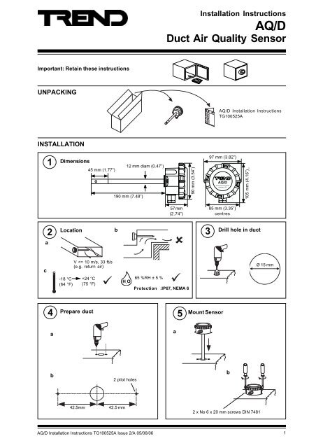
<strong>Installation</strong> <strong>Instructions</strong><br />
<strong>AQ</strong>/D<br />
<strong>Duct</strong> <strong>Air</strong> <strong>Quality</strong> <strong>Sensor</strong><br />
Important: Retain these instructions<br />
UNPACKING<br />
<strong>AQ</strong>/D <strong>Installation</strong> <strong>Instructions</strong><br />
TG100525A<br />
INSTALLATION<br />
1<br />
Dimensions<br />
12 mm diam (0.47”)<br />
45 mm (1.77”)<br />
190 mm (7.48”)<br />
90 mm (3.54”)<br />
97 mm (3.82”)<br />
<strong>AQ</strong>/D<br />
<strong>Trend</strong> Control Systems<br />
Horsham, UK<br />
105 mm (4.16”)_<br />
57 mm<br />
(2.74”)<br />
85 mm (3.35”)<br />
centres<br />
2<br />
Location<br />
b<br />
3<br />
Drill hole in duct<br />
a<br />
c<br />
-18 °C<br />
(64 °F)<br />
V
<strong>AQ</strong>/D<br />
<strong>Installation</strong> <strong>Instructions</strong><br />
INSTALLATION (Continued)<br />
a<br />
6<br />
Remove lid<br />
7<br />
b<br />
Remove Connector<br />
Caution: This unit contains static<br />
sensitive devices.<br />
Suitable anti-static<br />
precautions should be<br />
taken throughtout the operation to<br />
prevent damage to the units.<br />
BS EN100015/1 Basic<br />
Specification: protection of<br />
electrostatic sensitive devices.<br />
8<br />
Insert cable through gland<br />
9<br />
either use<br />
flexible conduit<br />
Check link is in ‘Run’ position<br />
View of pcb from surface<br />
mount side<br />
Run position<br />
or use<br />
M20 cable gland<br />
Cal<br />
position<br />
10<br />
Wire to Controller<br />
" 8 8 2<br />
4 K + = <br />
24V 0V OP<br />
IQ2<br />
24V (AUX)<br />
C (0V)<br />
IN<br />
IQ analogue input<br />
channel linked for<br />
voltage (V)<br />
, 8 4 8 4<br />
) , 7 5 6 , - ) ;<br />
<br />
24V 0V OP<br />
IQ3<br />
Note that sensor requires 96 mA from<br />
24 V supply<br />
Use auxiliary 24 Vdc output terminal as maximum current = 96 mA<br />
0 (0V)<br />
N (in)<br />
24V<br />
N<br />
IQ analogue input<br />
channel linked for<br />
voltage (V)<br />
11<br />
Replace connector<br />
12<br />
Ensure clean<br />
13<br />
Set minimum delay<br />
environment<br />
24V 0V OP<br />
Run<br />
Cal<br />
LD1 VR1 VR2<br />
ADJUST DELAY<br />
- +<br />
clean air<br />
- +<br />
Delay<br />
2 <strong>AQ</strong>/D <strong>Installation</strong> <strong>Instructions</strong> TG100525A Issue 2/A 05/06/06
<strong>Installation</strong> <strong>Instructions</strong><br />
<strong>AQ</strong>/D<br />
INSTALLATION (Continued)<br />
14<br />
Wait<br />
15<br />
Measure Output<br />
V = 1 to 3 V<br />
8<br />
0V<br />
IN<br />
24V<br />
V < 1 or > 3V<br />
- recalibrate<br />
<strong>AQ</strong>/D Data Sheet<br />
91-2747<br />
30 mins<br />
16<br />
Set delay<br />
17<br />
Replace lid<br />
(0 mins)<br />
Min<br />
12 mins)<br />
Max<br />
a b c<br />
24V<br />
0V OP<br />
Run<br />
Cal<br />
LD1 VR1 VR2<br />
ADJUST DELAY<br />
- +<br />
- +<br />
Delay<br />
Note that IP67 (NEMA6) rating is only achieved if the sensor is<br />
correctly installed with cable or conduit connection fully tightened<br />
18<br />
Configure IQ<br />
13<br />
or<br />
13<br />
IQ Configuration Manual 90-1533<br />
19<br />
Set up IQ <strong>Sensor</strong> type<br />
It is recommended to use SET (software tool) for the setting of the sensor type module. For all IQ2 series controllers with<br />
firmware version 2.1 or greater, or IQ3 series controllers, the following SET Unique <strong>Sensor</strong> Reference should be used:<br />
<strong>Air</strong> <strong>Quality</strong> V<br />
If not using SET, use the following table for all IQ2 series controllers of firmware version 2.1 or greater or IQ3 controllers;<br />
for all other IQ controllers see <strong>Sensor</strong> Scaling Reference Card TB100521A.<br />
tYpe <strong>Sensor</strong> digI/P Driver Function loGic Loop scHedule seQnc Analog<br />
digBit Knob sWitch Time Zone Oss User addRess intcoN calarM reView Plot<br />
calEndar<br />
= <br />
<strong>Air</strong> <strong>Quality</strong> (0-100%)<br />
0 = good 100 = bad<br />
Voltage<br />
Yx<br />
TYPE x<br />
:<br />
=<br />
S=5 (characterise )<br />
Y=, E=, U=, L=, P=<br />
I1 to I2=, O1 to O2=<br />
Y I nput type<br />
0 (volts )<br />
E Exponent<br />
3<br />
U Upper<br />
100<br />
L Lower<br />
0<br />
P Points<br />
2<br />
x Ix<br />
Ox<br />
1 0 0<br />
2 10<br />
100<br />
<strong>AQ</strong>/D <strong>Installation</strong> <strong>Instructions</strong> TG100525A Issue 2/A 05/06/06<br />
3
<strong>AQ</strong>/D<br />
<strong>Installation</strong> <strong>Instructions</strong><br />
INSTALLATION (Continued)<br />
20<br />
Test sytem<br />
0 100<br />
e.g. return air<br />
13<br />
Note that a burn in period of 2 to 3 days is required to ensure a stable and repeatable output.<br />
DISPOSAL<br />
WEEE Directive :<br />
At the end of their useful life the packaging ,<br />
product, and batteries should be disposed of<br />
by a suitable recycling centre.<br />
Do not dispose of with normal household waste.<br />
Do not burn.<br />
Manufactured for and on behalf of the Environmental and Combustion Controls Division of Honeywell Technologies Sàrl, Ecublens, Route<br />
du Bois 37,Switzerland by its Authorized Representative, <strong>Trend</strong> Control Systems Limited.<br />
<strong>Trend</strong> Control Systems Limited reserves the right to revise this publication from time to time and make changes to the content<br />
hereof without obligation to notify any person of such revisions or changes.<br />
<strong>Trend</strong> Control Systems Limited<br />
P.O. Box 34, Horsham, West Sussex, RH12 2YF, UK. Tel:+44 (0)1403 211888 Fax:+44 (0)1403 241608 www.trend-controls.com<br />
<strong>Trend</strong> Control Systems USA<br />
6670 185th Avenue NE, Redmond, Washington 98052, USA. Tel: (425)869-8400, Fax: (425)869-8445 www.trend-controls.com<br />
4 <strong>AQ</strong>/D <strong>Installation</strong> <strong>Instructions</strong> TG100525A Issue 2/A 05/06/06


