DATA SHEET
DATA SHEET
DATA SHEET

You also want an ePaper? Increase the reach of your titles
YUMPU automatically turns print PDFs into web optimized ePapers that Google loves.
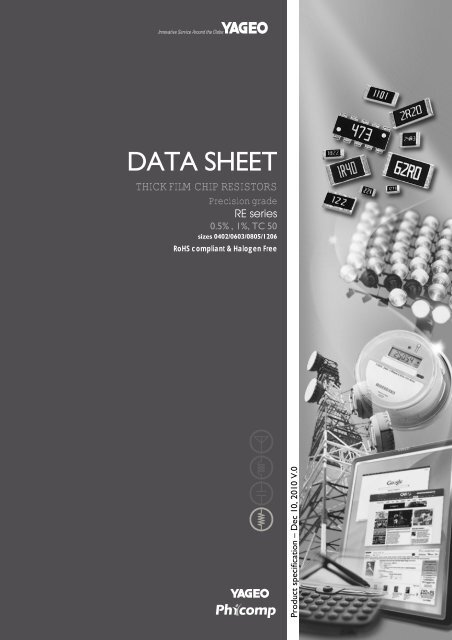
<strong>DATA</strong> <strong>SHEET</strong><br />
THICK FILM CHIP RESISTORS<br />
Precision grade<br />
RE series<br />
0.5% , 1%, TC 50<br />
sizes 0402/0603/0805/1206<br />
RoHS compliant & Halogen Free<br />
Product specification – Dec 10, 2010 V.0
Chip Resistor Surface Mount<br />
RE SERIES 0402 to 1206<br />
Product specification 2<br />
7<br />
SCOPE<br />
This specification describes<br />
RE0402 to RE1206 ultra precision<br />
chip resistors with lead-free<br />
terminations made by thick film<br />
process.<br />
APPLICATIONS<br />
•Converters<br />
•Printer equipment<br />
•Server board<br />
•Telecom<br />
•Consumer<br />
FEATURES<br />
•Halogen Free Epoxy<br />
•RoHS compliant<br />
- Products with lead free<br />
terminations meet RoHS<br />
requirements<br />
- Pb-glass contained in electrodes,<br />
resistor element and glass are<br />
exempted by RoHS<br />
•Reducing environmentally<br />
hazardous wastes<br />
•High component and equipment<br />
reliability<br />
•Saving of PCB space<br />
•None forbidden-materials used<br />
in products/production<br />
ORDERING INFORMATION - GLOBAL PART NUMBER & 12NC<br />
Both part numbers are identified by the series, size, tolerance, packing<br />
type, temperature coefficient, taping reel and resistance value.<br />
YAGEO BRAND ordering code<br />
GLOBAL PART NUMBER (PREFERRED)<br />
RE XXXX X X X XX XXXX L<br />
(1) (2) (3) (4) (5) (6) (7)<br />
(1) SIZE<br />
0402 / 0603 / 0805 / 1206<br />
(2) TOLERANCE<br />
D = ±0.5%<br />
F = ±1%<br />
(3) PACKAGING TYPE<br />
R = Paper/PE taping reel<br />
(4) TEMPERATURE COEFFICIENT OF RESISTANCE<br />
E = 50 ppm/°C<br />
(5) TAPING REEL<br />
07 = 7 inch dia. Reel<br />
10 = 10 inch dia. Reel<br />
13 = 13 inch dia. Reel<br />
(6) RESISTANCE VALUE<br />
There are 2~4 digits indicated the resistor value. Letter R/K/M is decimal point, no need<br />
to mention the last zero after R/K/M, e.g.1K2, not 1K20.<br />
Detailed resistance rules show in table of “Resistance rule of global part number”.<br />
(7) DEFAULT CODE<br />
Letter L is system default code for order only (Note)<br />
Resistance rule of global part<br />
number<br />
Resistance code rule Example<br />
XXRX<br />
(10 to 97.6 Ω)<br />
XXXR<br />
(100 to 976 Ω)<br />
XKXX<br />
(1 to 9.76 KΩ)<br />
XMXX<br />
(1 MΩ)<br />
10R = 10 Ω<br />
97R6 = 97.6 Ω<br />
100R = 100 Ω<br />
1K = 1,000 Ω<br />
9K76 = 9760 Ω<br />
1M = 1,000,000 Ω<br />
ORDERING EXAMPLE<br />
The ordering code of a RE0603<br />
chip resistor, TC 50 value 56 X with<br />
±0.5% tolerance, supplied in 7-inch<br />
tape reel is: RE0603DRE0756RL.<br />
NOTE<br />
1. All our RSMD products meet RoHS<br />
compliant and Halogen Free. "LFP" of<br />
the internal 2D reel label mentions<br />
"Lead Free Process"<br />
2. On customized label, "LFP" or specific<br />
symbol can be printed<br />
Dec 10, 2010 V.0<br />
www.yageo.com
YNSC004<br />
ynsc015<br />
ynsc007<br />
Chip Resistor Surface Mount<br />
RE SERIES 0402 to 1206<br />
Product specification 3<br />
7<br />
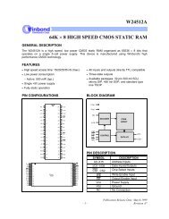
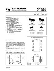
MARKING<br />
RE0805 / RE1206<br />
00<br />
Fig. 1 Value = 10 kΩ<br />
Either resistance in E-24 or E-96: 4 digits<br />
First three digits for significant figure and 4th digit for number of zeros<br />
RE0603<br />
Fig. 2 Value = 12 kΩ<br />
E-24 series: 3 digits<br />
First two digits for significant figure and 3rd digit for number of zeros<br />
Fig. 3 Value = 12.4 kΩ<br />
E-96 series: 3 digits for 0603±1% EIA-96 marking method<br />
RE0402<br />
Fig. 4<br />
No marking<br />
For further marking information, please see special data sheet “Chip resistors marking”.<br />
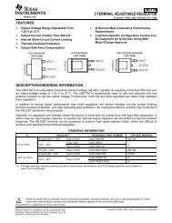
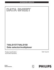
CONSTRUCTION<br />
The resistors are constructed out of a high-grade ceramic<br />
body. Internal metal electrodes are added at each end and<br />
connected by a resistive layer. The resistive layer is adjusted<br />
to give the approximate required resistance and laser cutting<br />
of this resistive layer that achieves tolerance trims the value.<br />
The resistive layer is covered with a protective coat and<br />
printed with the resistance value. Finally, the two external<br />
terminations (matte tin) are added. See fig. 5.<br />
DIMENSION<br />
Table 1 For outlines see fig. 5<br />
TYPE L (mm) W (mm) H (mm) I1 (mm) I2 (mm)<br />
OUTLINES<br />
For dimension see Table 1<br />
H<br />
I 2<br />
I 1<br />
marking layer<br />
protective coat<br />
resistive layer<br />
inner electrode<br />
termination (Ni/ matte tin)<br />
ceramic substrate<br />
RE0402 1.00 ±0.05 0.50 ±0.05 0.32 ±0.05 0.20 ±0.10 0.25 ±0.10<br />
RE0603 1.60 ±0.10 0.80 ±0.10 0.45 ±0.10 0.25 ±0.15 0.25 ±0.15<br />
RE0805 2.00 ±0.10 1.25 ±0.10 0.50 ±0.10 0.35 ±0.20 0.35 ±0.20<br />
RE1206 3.10 ±0.10 1.60 ±0.10 0.55 ±0.10 0.45 ±0.20 0.40 ±0.20<br />
W<br />
L<br />
YNSC064<br />
Fig. 5 Chip resistor outlines<br />
Dec 10, 2010 V.0<br />
www.yageo.com
Chip Resistor Surface Mount<br />
RE SERIES 0402 to 1206<br />
Product specification 4<br />
7<br />
ELECTRICAL CHARACTERISTICS<br />
Table 2<br />
TYPE<br />
RESISTANCE<br />
RANGE<br />
OPERATING<br />
TEMPERATURE RANGE<br />
POWER<br />
RATING<br />
MAXIMUM<br />
WORKING<br />
VOLTAGE<br />
DIELECTRIC<br />
WITHSTAND<br />
VOLTAGE<br />
MAXIMUM<br />
OVERLOAD<br />
VOLTAGE<br />
TEMPERATURE<br />
COEFFICIENT OF<br />
RESISTANCE<br />
RE0402 10 Ω to 1 MΩ –55 °C to +155 °C 1/16 W 50 V 100 V 100 V ±50 ppm/°C<br />
RE0603 10 Ω to 1 MΩ –55 °C to +155 °C 1/10 W 50 V 100 V 100 V ±50 ppm/°C<br />
RE0805 10 Ω to 1 MΩ –55 °C to +155 °C 1/8 W 150 V 300 V 300 V ±50 ppm/°C<br />
RE1206 10 Ω to 1 MΩ –55 °C to +155 °C 1/4 W 200 V 500 V 400 V ±50 ppm/°C<br />
NOTE<br />
The maximum working voltage that may be continuously applied to the resistor element, see “IEC publication 60115-8”<br />
FOOTPRINT AND SOLDERING PROFILES<br />
For recommended footprint and soldering profiles, please see the special data sheet “Chip resistors mounting”.<br />
PACKING STYLE AND PACKAGING QUANTITY<br />
Table 3 Packing style and packaging quantity<br />
PACKING STYLE REEL DIMENSION RE0402 RE0603 RE0805 RE1206<br />
Paper/PE taping reel (R) 7" (178 mm) 10,000 5,000 5,000 5,000<br />
10" (254 mm) 20,000 10,000 10,000 10,000<br />
13" (330 mm) 50,000 20,000 20,000 20,000<br />
NOTE<br />
1. For Paper/Embossed tape and reel specification/dimensions, please see the special data sheet “Chip resistors packing”<br />
FUNCTIONAL DESCRIPTION<br />
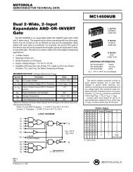
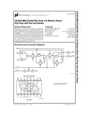
POWER RATING<br />
Each type rated power at 70°C:<br />
RE0402=1/16 W, RE0603=1/10 W, RE0805=1/8 W,<br />
RE1206=1/4 W<br />
RATED VOLTAGE<br />
The DC or AC (rms) continuous working voltage<br />
corresponding to the rated power is determined by<br />
the following formula:<br />
V=√(P X R)<br />
or max. working voltage whichever is less<br />
Where<br />
V=Continuous rated DC or<br />
AC (rms) working voltage (V)<br />
P=Rated power (W)<br />
R=Resistance value (X)<br />
handbook, halfpage<br />
P<br />
(%P rated)<br />
100<br />
50<br />
0<br />
55 0<br />
50<br />
70 100<br />
MLB206_2<br />
155<br />
o<br />
T amb ( C)<br />
Fig. 6 Maximum dissipation (P) in percentage of rated power as a<br />
function of the operating ambient temperature (T amb )<br />
Dec 10, 2010 V.0<br />
www.yageo.com
Chip Resistor Surface Mount<br />
RE SERIES 0402 to 1206<br />
Product specification 5<br />
7<br />
TESTS AND REQUIREMENTS<br />
Table 4 Test condition, procedure and requirements<br />
TEST TEST METHOD PROCEDURE REQUIREMENTS<br />
Life/Endurance IEC 60115-1 4.25.1 At 70±5 °C for 1,000 hours, RCWV applied for ±(3%+0.05 Ω)<br />
1.5 hours on, 0.5 hour off, still air required<br />
High<br />
Temperature<br />
Exposure/<br />
Endurance at<br />
Upper Category<br />
Temperature<br />
IEC 60068-2-2 1,000 hours at 155±5 °C, unpowered ±(3%+0.05 Ω)<br />
Moisture<br />
Resistance<br />
MIL-STD-202G Method-106G Each temperature / humidity cycle is defined at 8<br />
hours, 3 cycles / 24 hours for 10d. with 25 °C /<br />
65 °C 95% R.H, without steps 7a & 7b,<br />
unpowered<br />
Parts mounted on test-boards, without<br />
condensation on parts<br />
Measurement at 24±2 hours after<br />
test conclusion<br />
±(3%+0.05 Ω)<br />
Thermal Shock MIL-STD-202G Method-107G -55/+125 °C<br />
Number of cycles required is 300. Devices<br />
unmounted<br />
Maximum transfer time is 20 seconds. Dwell time<br />
is 15 minutes. Air – Air<br />
±(1%+0.05 Ω)<br />
Short Time<br />
Overload<br />
IEC60115-1 4.13<br />
2.5 times of rated voltage or maximum overload<br />
voltage whichever is less for 5 sec at room<br />
temperature<br />
±(1%+0.05 Ω)<br />
No visible damage<br />
Board Flex/<br />
Bending<br />
IEC 60068-2-21<br />
Chips mounted on a 90mm glass epoxy resin<br />
PCB (FR4)<br />
Bending: see table 5 for each size<br />
±(1%+0.05 Ω)<br />
No visible damage<br />
Bending time: 60±5 seconds<br />
www.yageo.com<br />
Dec 10, 2010 V.0
Chip Resistor Surface Mount<br />
RE SERIES 0402 to 1206<br />
Product specification 6<br />
7<br />
TEST TEST METHOD PROCEDURE REQUIREMENTS<br />
Solderability<br />
- Wetting IPC/JEDEC J-STD-002B test B Electrical Test not required<br />
Magnification 50X<br />
SMD conditions:<br />
1 st step: method B, aging 4 hours at 155°C<br />
dry heat<br />
2 nd step: leadfree solder bath at 245±3°C<br />
Dipping time: 3±0.5 seconds<br />
Well tinned (≥95%<br />
covered)<br />
No visible damage<br />
- Leaching IPC/JEDEC J-STD-002B test D Leadfree solder, 260 °C, 30 seconds<br />
immersion time<br />
No visible damage<br />
- Resistance to<br />
Soldering Heat<br />
IEC 60068-2-58<br />
Condition B, no pre-heat of samples.<br />
Leadfree solder, 260 °C, 10 seconds<br />
immersion time<br />
Procedure 2 for SMD: devices fluxed and<br />
cleaned with isopropanol<br />
±(1%+0.05 Ω)<br />
No visible damage<br />
Table 5 Bending for sizes 0402 to 1206<br />
TYPE RE0402 RE0603 RE0805 RE1206<br />
Specification (mm) 5 3 3 2<br />
Dec 10, 2010 V.0<br />
www.yageo.com
Chip Resistor Surface Mount<br />
RE SERIES 0402 to 1206<br />
Product specification 7<br />
7<br />
REVISION HISTORY<br />
REVISION DATE CHANGE NOTIFICATION DESCRIPTION<br />
Version 0 Dec 10, 2010 - - New datasheet for thick film ultra precision chip resistors sizes of<br />
0201/0402/0603/0805/1206, 0.5%, 1%, TC50 with lead-free terminations<br />
“ Yageo reserves all the rights for revising the content of this datasheet without further notification, as long as the products itself are unchanged. Any<br />
product change will be announced by PCN.”<br />
Dec 10, 2010 V.0<br />
www.yageo.com