Assembly Instructions - Wenger Corporation
Assembly Instructions - Wenger Corporation Assembly Instructions - Wenger Corporation
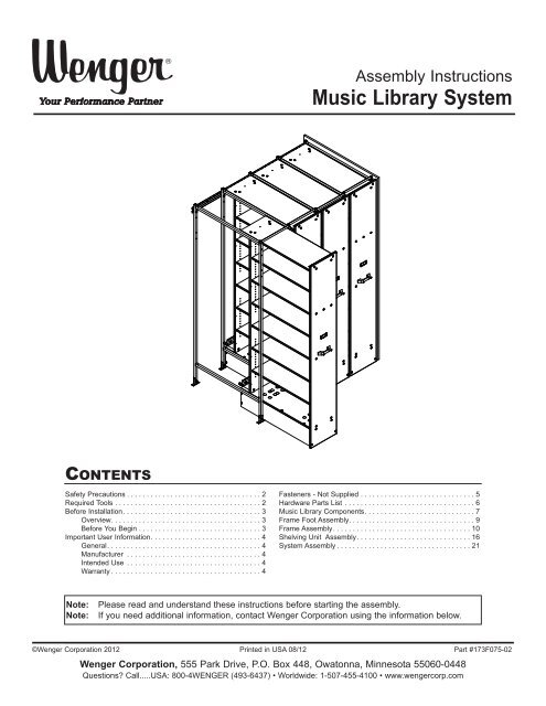
Assembly Instructions Music Library System CONTENTS Safety Precautions . . . . . . . . . . . . . . . . . . . . . . . . . . . . . . . . . . 2 Required Tools . . . . . . . . . . . . . . . . . . . . . . . . . . . . . . . . . . . . . 2 Before Installation. . . . . . . . . . . . . . . . . . . . . . . . . . . . . . . . . . . 3 Overview. . . . . . . . . . . . . . . . . . . . . . . . . . . . . . . . . . . . . . 3 Before You Begin . . . . . . . . . . . . . . . . . . . . . . . . . . . . . . . 3 Important User Information. . . . . . . . . . . . . . . . . . . . . . . . . . . . 4 General. . . . . . . . . . . . . . . . . . . . . . . . . . . . . . . . . . . . . . . 4 Manufacturer . . . . . . . . . . . . . . . . . . . . . . . . . . . . . . . . . . 4 Intended Use . . . . . . . . . . . . . . . . . . . . . . . . . . . . . . . . . . 4 Warranty . . . . . . . . . . . . . . . . . . . . . . . . . . . . . . . . . . . . . . 4 Fasteners - Not Supplied . . . . . . . . . . . . . . . . . . . . . . . . . . . . . 5 Hardware Parts List . . . . . . . . . . . . . . . . . . . . . . . . . . . . . . . . . 6 Music Library Components. . . . . . . . . . . . . . . . . . . . . . . . . . . . 7 Frame Foot Assembly. . . . . . . . . . . . . . . . . . . . . . . . . . . . . . . . 9 Frame Assembly. . . . . . . . . . . . . . . . . . . . . . . . . . . . . . . . . . . 10 Shelving Unit Assembly. . . . . . . . . . . . . . . . . . . . . . . . . . . . . 16 System Assembly . . . . . . . . . . . . . . . . . . . . . . . . . . . . . . . . . . 21 Note: Note: Please read and understand these instructions before starting the assembly. If you need additional information, contact Wenger Corporation using the information below. ©Wenger Corporation 2012 Printed in USA 08/12 Part #173F075-02 Wenger Corporation, 555 Park Drive, P.O. Box 448, Owatonna, Minnesota 55060-0448 Questions Call.....USA: 800-4WENGER (493-6437) • Worldwide: 1-507-455-4100 • www.wengercorp.com
- Page 2 and 3: SAFETY PRECAUTIONS Throughout this
- Page 4 and 5: IMPORTANT USER INFORMATION GENERAL
- Page 6 and 7: HARDWARE PARTS LIST 1 2 3 4 Capscre
- Page 8 and 9: MUSIC LIBRARY COMPONENTS (CONTINUED
- Page 10 and 11: FRAME ASSEMBLY Read the “Before I
- Page 12 and 13: FRAME ASSEMBLY (CONTINUED) 5. Keep
- Page 14 and 15: FRAME ASSEMBLY (CONTINUED) 8. Attac
- Page 16 and 17: SHELVING UNIT ASSEMBLY 1. Install t
- Page 18 and 19: SHELVING UNIT ASSEMBLY (CONTINUED)
- Page 20 and 21: SHELVING UNIT ASSEMBLY (CONTINUED)
- Page 22 and 23: SYSTEM ASSEMBLY (CONTINUED) 3. Atta
- Page 24: SYSTEM ASSEMBLY (CONTINUED) 12. Ins
<strong>Assembly</strong> <strong>Instructions</strong><br />
Music Library System<br />
CONTENTS<br />
Safety Precautions . . . . . . . . . . . . . . . . . . . . . . . . . . . . . . . . . . 2<br />
Required Tools . . . . . . . . . . . . . . . . . . . . . . . . . . . . . . . . . . . . . 2<br />
Before Installation. . . . . . . . . . . . . . . . . . . . . . . . . . . . . . . . . . . 3<br />
Overview. . . . . . . . . . . . . . . . . . . . . . . . . . . . . . . . . . . . . . 3<br />
Before You Begin . . . . . . . . . . . . . . . . . . . . . . . . . . . . . . . 3<br />
Important User Information. . . . . . . . . . . . . . . . . . . . . . . . . . . . 4<br />
General. . . . . . . . . . . . . . . . . . . . . . . . . . . . . . . . . . . . . . . 4<br />
Manufacturer . . . . . . . . . . . . . . . . . . . . . . . . . . . . . . . . . . 4<br />
Intended Use . . . . . . . . . . . . . . . . . . . . . . . . . . . . . . . . . . 4<br />
Warranty . . . . . . . . . . . . . . . . . . . . . . . . . . . . . . . . . . . . . . 4<br />
Fasteners - Not Supplied . . . . . . . . . . . . . . . . . . . . . . . . . . . . . 5<br />
Hardware Parts List . . . . . . . . . . . . . . . . . . . . . . . . . . . . . . . . . 6<br />
Music Library Components. . . . . . . . . . . . . . . . . . . . . . . . . . . . 7<br />
Frame Foot <strong>Assembly</strong>. . . . . . . . . . . . . . . . . . . . . . . . . . . . . . . . 9<br />
Frame <strong>Assembly</strong>. . . . . . . . . . . . . . . . . . . . . . . . . . . . . . . . . . . 10<br />
Shelving Unit <strong>Assembly</strong>. . . . . . . . . . . . . . . . . . . . . . . . . . . . . 16<br />
System <strong>Assembly</strong> . . . . . . . . . . . . . . . . . . . . . . . . . . . . . . . . . . 21<br />
Note:<br />
Note:<br />
Please read and understand these instructions before starting the assembly.<br />
If you need additional information, contact <strong>Wenger</strong> <strong>Corporation</strong> using the information below.<br />
©<strong>Wenger</strong> <strong>Corporation</strong> 2012 Printed in USA 08/12 Part #173F075-02<br />
<strong>Wenger</strong> <strong>Corporation</strong>, 555 Park Drive, P.O. Box 448, Owatonna, Minnesota 55060-0448<br />
Questions Call.....USA: 800-4WENGER (493-6437) • Worldwide: 1-507-455-4100 • www.wengercorp.com
SAFETY PRECAUTIONS<br />
Throughout this manual you may find CAUTIONS and WARNINGS which are defined as follows:<br />
• WARNING means that failure to follow the instruction may result in serious injury or death.<br />
• CAUTION means that failure to follow the instruction may result in serious injury or damage to<br />
property.<br />
Read all of these safety instructions before assembling and installing the Music Library System.<br />
! CAUTION<br />
Make sure anyone<br />
assembling or installing the<br />
Music Library System has<br />
read and understands this<br />
manual.<br />
! CAUTION<br />
Failure to comply with<br />
Warnings and Cautions in<br />
this document can result in<br />
damage to property or<br />
serious injury.<br />
! CAUTION<br />
Always wear safety glasses<br />
and gloves when assembling<br />
or installing the Music Library<br />
System.<br />
REQUIRED TOOLS<br />
• Phillips Screwdriver<br />
• 3<br />
/8”, 7 /16” and 1 /2” Open End Wrench<br />
• Hammer<br />
• Power Driver with 3 /8” Chuck<br />
• Power Drill with 1 /8” Drill Bits<br />
• 3<br />
/8” Hex Driver<br />
• 5<br />
/32 Hex Insert Bit<br />
• Phillips Screwdriver Bit<br />
• Carpenter’s Level<br />
• Carpenter’s Square<br />
• Special Bar for Spacing Guide Frames<br />
(supplied with the system).<br />
2
BEFORE INSTALLATION<br />
OVERVIEW<br />
• This system should be installed only by skilled technical persons, and only after carefully studying<br />
these instructions.<br />
• These instructions assume that you will install the system next to a side wall (either side).<br />
This is the preferred method.<br />
• If there won’t be a wall on either side, you must (for safety) install a minimum of four shelving<br />
units in a row.<br />
• The installation site must be level - no more than 1 /4" variation in a 6' distance (in both directions).<br />
• Do not install over carpeted floors that have a foam padding underneath<br />
(because the shelving unit will be too hard to roll).<br />
• The framework must be properly anchored to a rear wall and to the floor<br />
(according to the instructions in this manual).<br />
• For smooth operation, the framework must be assembled square with the rear wall and must be<br />
plumb. Recheck carefully before securing the unit to the rear wall and floor.<br />
BEFORE YOU BEGIN<br />
• Read the complete assembly procedure before beginning the assembly.<br />
• The individual shelving units must be assembled and the feet attached to the guide frames before<br />
they can be installed in the system.<br />
If space is limited, it may be more convenient to assemble the guide framework and secure it to the<br />
wall and floor — then assemble and install shelving units one at a time.<br />
• Open one shipping carton at a time. Remove all items from the carton, and lay them out<br />
approximately in their final position.<br />
3
IMPORTANT USER INFORMATION<br />
GENERAL<br />
Copyright© 2012 by <strong>Wenger</strong> <strong>Corporation</strong>. Printed and bound in the United States of America.<br />
All rights reserved. No part of the contents of this manual may be reproduced, copied, or transmitted in<br />
any form or by any means including graphic, electronic, or mechanical methods or photocopying,<br />
recording, or information storage and retrieval systems without the written permission of the publisher,<br />
unless it is for the purchaser's personal use.<br />
The information in this manual is subject to change without notice and does not represent a commitment<br />
on the part of <strong>Wenger</strong> <strong>Corporation</strong>. <strong>Wenger</strong> <strong>Corporation</strong> does not assume any responsibility for any<br />
errors that may appear in this manual.<br />
In no event will <strong>Wenger</strong> <strong>Corporation</strong> be liable for technical or editorial omissions made herein, nor for direct,<br />
indirect, special, incidental, or consequential damages resulting from the use or defect of this manual.<br />
The information in this document is not intended to cover all possible conditions and situations<br />
that might occur. The end user must exercise caution and common sense when assembling or<br />
installing <strong>Wenger</strong> <strong>Corporation</strong> products. If any questions or problems arise, call <strong>Wenger</strong> <strong>Corporation</strong><br />
at 800-4WENGER (493-6437).<br />
MANUFACTURER<br />
The Music Library System is manufactured by:<br />
<strong>Wenger</strong> <strong>Corporation</strong><br />
555 Park Drive<br />
Owatonna, MN 55060<br />
800-4WENGER (493-6437) • 1-507-455-4100<br />
www.wengercorp.com<br />
INTENDED USE<br />
• This product is intended for indoor use in normal ambient temperature and humidity<br />
conditions — it must not be exposed to prolonged outside weather conditions.<br />
• This product is intended to be assembled only as described in these instructions.<br />
WARRANTY<br />
This product is guaranteed free of defects in materials and workmanship for ten full years from date<br />
of shipment. A full warranty statement is available upon request.<br />
4
FASTENERS - NOT SUPPLIED<br />
Because materials and construction of floors and walls can vary, fasteners for attaching the<br />
Music Library System to the structure are not provided. The installer must choose the appropriate<br />
fastener and follow the manufacturer’s instructions.<br />
! CAUTION<br />
Inferior or improperly installed<br />
fasteners could cause the<br />
Music Library System to tip over.<br />
Determine the construction of the walls and floor.<br />
Wall Mounting Rail Fastener Guidelines:<br />
For wood stud or metal stud walls covered with gypsum, use #10 or larger screws that will<br />
provide a minimum of 2” of penetration into the stud. Self-drilling hex head screws are acceptable<br />
and eliminate the need to drill a pilot hole. Each stud will require two screws. Consult <strong>Wenger</strong><br />
if the stud spacing is greater than 24”.<br />
For masonry walls or block walls, concrete screws or expanding drive nail fasteners can be used.<br />
Toggle bolts should be used when anchoring into hollow wall sections. Power driven fasteners<br />
should not be used. Fasteners should be a minimum of 1 /4” diameter and 2” long.<br />
Fasteners should be applied every 16” on center and within 4” of each end.<br />
Guide Frame Floor Fastener Guidelines:<br />
For floors with wood construction, attachment should be made with sheet metal screws or<br />
lag screws that are #10 or larger and a minumum of 2” long. Self-drilling hex head screws are<br />
acceptable and eliminate the need to drill a pilot hole. Each guide frame will require four fasteners.<br />
For concrete floors, attachment should be made with concrete screws, expanding drive nails<br />
or wedge type anchors. Fasteners should be a minimum of 1 /4” diameter and 2” long.<br />
Each guide frame will require four fasteners.<br />
Note: Each wall and floor connection must be rated for a minimum of 500 lbs of tension.<br />
Other fasteners may be used if the connection strength requirement is met.<br />
5
HARDWARE PARTS LIST<br />
1<br />
2<br />
3<br />
4<br />
Capscrew, 1 /4-20 x 1 3 /4"<br />
Washer,<br />
1<br />
/4" ID x 7 /8” OD<br />
Lock Nut, 1 /4-20<br />
Cap Nut, #10-24<br />
5<br />
6 7<br />
8<br />
Shelf Support Pin<br />
Step Pin, 1 /4" x 1”<br />
Machine Screw,<br />
1<br />
/4-20 x 1 3 /8”<br />
Sheet Metal Screw,<br />
Phillips, #8-15 x 1 1 /4”<br />
9<br />
10<br />
11<br />
12<br />
Wood Dowel,<br />
8 x 25 mm<br />
Sheet Metal Screw,<br />
Phillips, #6-18 x 1 /2”<br />
Particle Board Screw,<br />
7 x 50 mm<br />
Sheet Metal Screw,<br />
Phillips, #8 x 5 /8”<br />
13<br />
Screw, Phillips,<br />
#10-24 x 3 /4”<br />
*Fasteners applied to the Front Panel (15) may be colored to match the edgebanding of the system.<br />
6
MUSIC LIBRARY COMPONENTS<br />
14<br />
15<br />
16<br />
17<br />
Top Panel<br />
18<br />
Fixed Shelf<br />
19<br />
Back<br />
Panel<br />
Side Panel<br />
Front<br />
Panel<br />
Adjustable Shelf<br />
20<br />
21<br />
24<br />
27<br />
Card<br />
Holder<br />
Rear Support<br />
Channel<br />
Wall<br />
Bracket<br />
22<br />
25<br />
28<br />
Handle<br />
Bumper<br />
Bar<br />
Unit Movement<br />
Stop Cable<br />
23<br />
26<br />
Top Corner<br />
Gusset<br />
Base <strong>Assembly</strong><br />
End Cover Panel<br />
7
MUSIC LIBRARY COMPONENTS (CONTINUED)<br />
29<br />
30<br />
31<br />
32<br />
33<br />
Spacer Tool<br />
Tie Bar<br />
Guide<br />
Frame<br />
Foot<br />
Wall Channel<br />
Guide Frame<br />
8
FRAME FOOT ASSEMBLY<br />
1. Attach a Guide Frame Foot (32) to the bottom of each Guide Frame (31) leg<br />
using a 1 /4-20 x 1 3 /4” Capscrew (1), 1 /4” ID x 7 /8” Washer (2) and a 1 /4-20 Lock Nut (3).<br />
The Lock Nuts (3) and Washers (2) will face each other when both Guide Frame Feet (32)<br />
are attached.<br />
Guide Frame<br />
(31)<br />
1<br />
/4-20 x 1 3 /4”<br />
Capscrew<br />
(1)<br />
Guide Frame<br />
Foot<br />
(32) 1<br />
/4-20<br />
Washer<br />
(2)<br />
1<br />
/4 ID x 7 /8 OD<br />
Lock Nut<br />
(3)<br />
1<br />
/4 ID x 7 /8 OD<br />
Lock Nut<br />
(3)<br />
1<br />
/4-20<br />
Washer<br />
(2)<br />
1<br />
/4-20 x 1 3 /4”<br />
Capscrew<br />
(1)<br />
Guide Frame<br />
Foot<br />
(32)<br />
9
FRAME ASSEMBLY<br />
Read the “Before Installation” section before proceeding.<br />
1. Determine where the Music Library System will be installed.<br />
If less than four units will be installed, the Guide Frame Assemblies will be installed 16” apart<br />
along the Wall Channel (33). Any excess Wall Channel will be cut off.<br />
Each assembled Shelf Unit measures:<br />
Closed position: 16” wide x 44” deep x 92” high (41 x 112 x 234 cm)<br />
Open position: 16” wide x 80” deep x 92” high (41 x 203 x 234 cm).<br />
2. Attach a Guide Frame <strong>Assembly</strong> to both ends of the Wall Channel (33) using<br />
a 1 /4-20 x 1 3 /4” Capscrew (1) and a 1 /4” x 7 /8” Washer (2) through the top holes of the<br />
Guide Frame <strong>Assembly</strong>.<br />
1<br />
/4-20<br />
Washer<br />
(2)<br />
Wall<br />
Channel<br />
(33)<br />
1<br />
/4-20 x 1 3 /4”<br />
Capscrew<br />
(1)<br />
1<br />
/4-20<br />
Washer<br />
(2) 1<br />
/4-20 x 1 3 /4”<br />
Capscrew<br />
(1)<br />
Guide Frame<br />
<strong>Assembly</strong><br />
Guide Frame<br />
<strong>Assembly</strong><br />
10
FRAME ASSEMBLY (CONTINUED)<br />
3. Position the Frame <strong>Assembly</strong> in the desired location, with:<br />
• The Wall Channel flush against the rear wall; and<br />
• The Feet of the first Guide Frame flush against the side wall.<br />
4. Plumb and square the unit. Remove any obstructions.<br />
IMPORTANT:<br />
• The Wall Channel must remain flat against the rear wall with the Feet of the<br />
Guide Frame Assemblies touching the floor; and<br />
• The top of the first Guide Frame <strong>Assembly</strong> should not be more than 1 1 /4" (3 cm)<br />
from the side wall.<br />
If necessary, bend or cut the Feet on the wall side of the Guide Frame <strong>Assembly</strong>).<br />
Keep the Wall Channel<br />
flat against the wall.<br />
Not more than 1 1 /4” (3 cm)<br />
between the top of the<br />
Guide Frame <strong>Assembly</strong><br />
and the side wall.<br />
Carpenter’s<br />
Square<br />
Carpenter’s<br />
Level<br />
If there is interference because<br />
the walls are not plumb and<br />
square, bend or cut the Feet on<br />
the wall side of the Guide Frame<br />
<strong>Assembly</strong>.<br />
11
FRAME ASSEMBLY (CONTINUED)<br />
5. Keep the Frame <strong>Assembly</strong> square and plumb.<br />
For smooth unit operation, the Frame <strong>Assembly</strong> must be square and plumb.<br />
Attach the Wall Channel to the wall using the appropriate fasteners and<br />
method described in the “Fasteners - Not Suppled” section.<br />
! CAUTION<br />
Inferior or improperly installed<br />
fasteners could cause the<br />
Music Library System to tip over.<br />
6. Continue to keep the first Guide Frame <strong>Assembly</strong> square and plumb.<br />
Attach the Feet to the floor using the appropriate fasteners and method described<br />
in the “Fasteners - Not Suppled” section.<br />
Attach<br />
Wall Channel to<br />
Back Wall<br />
Attach<br />
Guide Frame Feet<br />
to Floor<br />
Attach<br />
Guide Frame Feet<br />
to Floor<br />
Attach<br />
Guide Frame Feet<br />
to Floor<br />
Attach<br />
Guide Frame Feet<br />
to Floor<br />
12
FRAME ASSEMBLY (CONTINUED)<br />
7. Attach the front end of the first Guide Frame <strong>Assembly</strong> to the side wall<br />
(keep the Guide Frame <strong>Assembly</strong> square and plumb):<br />
• First, attach the Wall Bracket (27) to the side wall (7a).<br />
• Then, attach the Wall Bracket (27) to the Guide Frame <strong>Assembly</strong> (7b).<br />
IMPORTANT:<br />
If the Music Library System is not being installed next to a side wall, a minimum<br />
of four Shelving Units must be installed for stability.<br />
The Wall Bracket (27) will not be used and this step is skipped.<br />
a. Attach the Wall Bracket (27) to the side wall using the appropriate fasteners and method<br />
described in the “Fasteners - Not Suppled” section.<br />
The top of the Wall Bracket (27) should be flush with the underside of the cross bar<br />
at the top of the guide frame.<br />
! CAUTION<br />
Inferior or improperly installed<br />
fasteners could cause the<br />
Music Library System to tip over.<br />
b. Attach the Bracket to the Guide Frame:<br />
Drill 1 /8" hole into cross bar of Guide Frame.<br />
Attach the Bracket as shown with a<br />
#8 x 5 /8” Sheet Metal Screw (12).<br />
Wall Bracket<br />
(27)<br />
Wall<br />
Surface<br />
#8 x 5 /8” Sheet<br />
Metal Screw<br />
(12)<br />
If the Wall Bracket (27)<br />
extends beyond the<br />
edge of the cross bar,<br />
bend or cut off the<br />
excess to prevent<br />
interference with the<br />
shelving unit.<br />
IMPORTANT: If the Wall Bracket (27)<br />
extends beyond the edge of the cross bar,<br />
bend or cut off the excess to prevent<br />
interference with the shelving unit.<br />
13
FRAME ASSEMBLY (CONTINUED)<br />
8. Attach the remaining Guide Frame Assemblies to the<br />
Wall Channel (33) using a 1 /4-20 x 1 3 /4” Capscrew (1)<br />
and a 1 /4” ID x 7 /8” OD Washer (2) in each.<br />
NOTE: It may be more convenient to do<br />
steps 8, 9, 10 and 11 one<br />
Guide Frame <strong>Assembly</strong> at a time.<br />
1/4” ID x 7/8” OD<br />
Washer<br />
(2)<br />
1<br />
/4-20 x 1 3 /4”<br />
Capscrew<br />
(1)<br />
9. Insert Tie Bars (30) into the top of the front posts as shown.<br />
Note that alternating Tie Bars<br />
face in opposite directions.<br />
Tie Bars (30)<br />
(facing front)<br />
Tie Bars (30)<br />
(facing rear)<br />
14
FRAME ASSEMBLY (CONTINUED)<br />
10. Attach the Rear Foot of the Guide Frame <strong>Assembly</strong> to the floor<br />
using the appropriate fasteners and method described<br />
in the “Fasteners - Not Suppled” section.<br />
Use the provided Spacer Bar (29), and be sure the<br />
Guide Frame <strong>Assembly</strong> is plumb front-to-back.<br />
Only one fastener is needed per<br />
Guide Frame Foot (use either hole).<br />
11. Move the Spacer Bar (29) towards the front<br />
and attach the Front Foot to the floor using<br />
the same procedure.<br />
Spacer<br />
Bar<br />
(29)<br />
Attach<br />
Guide Frame Foot<br />
to Floor<br />
Spacer<br />
Bar<br />
(29)<br />
Attach<br />
Guide Frame Foot<br />
to Floor<br />
12. Install additional Wall Channels and Guide Frame Assemblies by<br />
repeating the previous steps while alternating to the lower holes<br />
in the Guide Frame Assemlies.<br />
Tighten all connections to the Wall Channel.<br />
If the last section will contain less than four shelving units,<br />
cut off the excess Wall Channel or shift it behind<br />
the previously installed Guide Frame Assemblies.<br />
Lower<br />
Hole<br />
Additional<br />
Wall Channel<br />
15
SHELVING UNIT ASSEMBLY<br />
1. Install two #10-24 Cap Nuts (4) in the inside face of the Front Panel (15).<br />
The Cap Nuts will be used by the fasteners that secure the Handle (22).<br />
NOTE: The Front Panel (15) is identified as being longer<br />
than the Back Panel (16).<br />
Inside Surface<br />
of Front Panel<br />
(15)<br />
#10-24<br />
Cap Nuts<br />
(4)<br />
3. a. Attach the Top Panel (17) to the Front Panel (15) using two 7 x 50 mm Particle Board<br />
Screws (11).<br />
Fasteners applied to the Front Panel (15) are colored to match the Edge Banding<br />
of the entire system.<br />
b. Attach the Center Fixed Shelf/Shelves (18) to the Front Panel (15) using<br />
four 8 x 25 mm Wood Dowels (9) and three 7 x 50 mm Particle Board Screws (11) in each.<br />
The Upper Fixed Shelf is used on 7-Shelf Systems only.<br />
c. Tighten all fasteners securely.<br />
Fixed Shelf<br />
(18)<br />
Upper Fixed Shelf<br />
(18)<br />
(7-Shelf Systems Only)<br />
8 x 25 mm<br />
Wood Dowels<br />
(9)<br />
8 x 25 mm<br />
Wood Dowels<br />
(9)<br />
Front Panel<br />
(15)<br />
(Outside Surface)<br />
8 x 25 mm<br />
Wood Dowels<br />
(9)<br />
7 x 50 mm<br />
Particle Board<br />
Screws (11)<br />
7 x 50 mm<br />
Particle Board<br />
Screws (11)<br />
7 x 50 mm<br />
Particle Board<br />
Screws (11)<br />
Top Panel<br />
(17)<br />
(Outside Surface)<br />
16
SHELVING UNIT ASSEMBLY (CONTINUED)<br />
3. Attach the Back Panel (16) to the Top Panel (17) using two 7 x 50 mm<br />
Particle Board Screws (11).<br />
Attach the Center Fixed Shelf/Shelves (18) to the<br />
Back Panel (16) using three 7 x 50 mm<br />
Particle Board Screws (11) in each.<br />
On a 6-Shelf System, the Back Panel (16)<br />
is not symmetrical and could be<br />
installed upside down.<br />
Be sure that the pre-drilled<br />
hole configurations<br />
match the rest of the<br />
system before<br />
attaching.<br />
7 x 50 mm<br />
Particle Board<br />
Screws (11)<br />
Back Panel<br />
(16)<br />
(Outside Surface)<br />
7 x 50 mm<br />
Particle Board<br />
Screws (11)<br />
4. Attach the two Top Corner Gussets (26) to the Shelving Unit <strong>Assembly</strong> using four<br />
1<br />
/4-20 x 1 3 /8” Machine Screws (7) and 1 /4-20 Lock Nuts (3) in each as shown.<br />
Note that Lock Nuts face each other on each Top Corner Gusset.<br />
1<br />
/4-20 Lock Nuts<br />
(3)<br />
Top Corner Gusset<br />
(26)<br />
1<br />
/4-20 Lock Nuts<br />
(3)<br />
1<br />
/4-20 x 1 3 /8”<br />
Machine Screws<br />
(7)<br />
17
SHELVING UNIT ASSEMBLY (CONTINUED)<br />
5. Insert two 8 x 25 mm Wood Dowels (9) into the front of the<br />
Base <strong>Assembly</strong> (23).<br />
Base <strong>Assembly</strong><br />
(23)<br />
8 x 25 mm<br />
Wood Dowels<br />
(9)<br />
6. Attach the Base <strong>Assembly</strong> to the Shelving Unit <strong>Assembly</strong> using:<br />
a. Two 7 x 50 mm Particle Board Screws (11) through the top of the Base <strong>Assembly</strong>.<br />
b. Four 7 x 50 mm Particle Board Screws (11) through the Front Panel.<br />
c. Two 1 /4-20 x 1 3 /8” Machine Screws (7) and 1 /4-20 Lock Nuts (3) through the Front Panel.<br />
d. Tighten all fasteners securely and tip the Shelving Unit <strong>Assembly</strong> upright.<br />
7 x 50 mm<br />
Particle Board Screws<br />
(11)<br />
7 x 50 mm<br />
Particle Board<br />
Screws<br />
(11)<br />
1<br />
/4-20 x 1 3 /8”<br />
Machine Screws<br />
(7)<br />
7 x 50 mm<br />
Particle Board Screws<br />
(11)<br />
18
SHELVING UNIT ASSEMBLY (CONTINUED)<br />
7. Attach the Rear Support Channel (24) to the Back Panel (16)<br />
using two 1 /4-20 x 1 3 /8” Machine Screws (7) and two 1 /4-20 Lock Nuts (3).<br />
1<br />
/4-20 x 1 3 /8”<br />
Machine Screws<br />
(7)<br />
1<br />
/4-20<br />
Lock Nuts<br />
(3)<br />
Rear Support<br />
Channel<br />
(24)<br />
19
SHELVING UNIT ASSEMBLY (CONTINUED)<br />
8. Check the Shelving Unit <strong>Assembly</strong> to<br />
be sure which is the preferred side<br />
for the Side Panel (14)<br />
(towards the side wall).<br />
Position the Side Panel (14) so the<br />
three pre-drilled holes align with<br />
one of the installed Fixed Shelves (18).<br />
Reverse the Side Panel (14)<br />
(bottom to top) if necessary.<br />
Side Wall<br />
on Left<br />
Side<br />
or<br />
Side Wall<br />
on Right<br />
Side<br />
Access From Left Side<br />
Access From Right Side<br />
9. Attach the Side Panel (14) to the proper side of the<br />
Shelving Unit <strong>Assembly</strong>.<br />
a. Place the Side Panel (14) into position.<br />
b. Install eight 1 /4” x 1” Step Pins (6).<br />
c. Pre-drill three 1 /8” diameter holes, 1” deep into the<br />
Fixed Shelf (18)<br />
(through the existing holes in the Side Panel).<br />
d. Install three #8-15 x 1 1 /4” Sheet Metal Screws (8)<br />
into the pre-drilled holes.<br />
Be careful not to damage the wood panels.<br />
1<br />
/4" x 1”<br />
Step Pin<br />
(6)<br />
#8-15 x 1 1 /4”<br />
Sheet Metal Screw<br />
(8)<br />
10. Repeat these steps to assemble all remaining<br />
Shelving Unit Assemblies.<br />
1<br />
/4" x 1”<br />
Step Pin<br />
(6)<br />
20
SYSTEM ASSEMBLY<br />
1. Roll a Shelving Unit <strong>Assembly</strong> into position between the<br />
first set of Guide Frames.<br />
Be sure that it can be freely moved in and out.<br />
2. Pull the Shelving Unit <strong>Assembly</strong> partially out and install<br />
the Bumper Bar (25) to the Rear Support Channel (24)<br />
using two 1 /4-20 x 1 3 /4” Capscrews (1),<br />
1<br />
/4” ID x 7 /8” OD Washers (2) and<br />
1<br />
/4-20 Lock Nuts (3).<br />
Fastener<br />
Locations<br />
1<br />
/4-20 x 1 3 /4”<br />
Capscrew<br />
1<br />
/4-20 x 1 3 /4”<br />
Capscrew<br />
(1)<br />
(1)<br />
1<br />
Bumper<br />
/4” ID x 7 /8”OD Bar<br />
Washers (25)<br />
(2)<br />
BACK VIEW<br />
1<br />
/4-20<br />
Lock Nuts<br />
(3)<br />
21
SYSTEM ASSEMBLY (CONTINUED)<br />
3. Attach a Unit Movement Stop Cable (28) to the Wall Channel using a<br />
1<br />
/4-20 x 1 3 /4” Capscrew (1), 1 /4” ID x 7 /8” OD Washer (2) and a 1 /4-20 Lock Nut (3).<br />
1<br />
/4-20 x 1 3 /4”<br />
Capscrew<br />
(1)<br />
Unit Movement<br />
Stop Cable<br />
(28)<br />
1<br />
/4-20 x 1 3 /4”<br />
Capscrew<br />
(1)<br />
Unit Movement<br />
Stop Cable<br />
(28)<br />
1<br />
/4” ID x 7 /8”OD<br />
Washers<br />
(2)<br />
1<br />
/4” ID x 7 /8”OD<br />
Washer<br />
(2)<br />
1<br />
/4-20<br />
Lock Nut<br />
(3)<br />
1<br />
/4-20<br />
Lock Nut<br />
(3)<br />
4. Attach the other end of<br />
the Unit Movement<br />
Stop Cable (28) to the<br />
Top Corner Gusset using a<br />
1<br />
/4-20 x 1 3 /4” Capscrew (1),<br />
two 1 /4” ID x 7 /8” OD Washers (2)<br />
and a 1 /4-20 Lock Nut (3).<br />
5. Roll the Shelving Unit <strong>Assembly</strong> in and out,<br />
making sure it is stopped by the Bumper Bar (25)<br />
and Unit Movement Stop Cable (28) at about the<br />
same time.<br />
If not, check that the Bumper Bar (26) is<br />
installed correctly.<br />
Unit Movement<br />
Stop Cable<br />
(28)<br />
6. Repeat these steps to Install the remaining<br />
Shelving Unit Assemblies.<br />
Bumper<br />
Bar<br />
(25)<br />
22
SYSTEM ASSEMBLY (CONTINUED)<br />
7. Install a Handle (22) on each Front Panel using two #10-24 x 3 /4”<br />
Phillips Head Screws (13) in the pre-drilled holes.<br />
8. Install a Card Holder (21) on each Front Panel using three<br />
#6-18 x 1 /2” Sheet Metal Screws (10).<br />
#6-18 x 1 /2”<br />
Sheet Metal Screws<br />
(10)<br />
Card<br />
Holder<br />
(21)<br />
Flip<br />
Open<br />
Handle<br />
(22)<br />
#10-24 x 3 /4”<br />
Phillips Head Screws<br />
(13)<br />
9. Place the Shelf Support Pins (5) (four per shelf) at the<br />
desired locations for the Adjustable Shelves (19).<br />
10. Slide the Adjustable Shelves (19) onto the<br />
Shelf Support Pins (5).<br />
Shelf<br />
Support Pin<br />
(5)<br />
11. Repeat these steps to Install the remaining<br />
Shelving Unit Assemblies.<br />
Fixed Shelf<br />
(7-Shelf Unit)<br />
(18)<br />
Fixed Shelf<br />
(18)<br />
Adjustable<br />
Shelf<br />
(19)<br />
23
SYSTEM ASSEMBLY (CONTINUED)<br />
12. Install the End Cover Panel (20) on the end of the Music Libray System.<br />
Keep the End Cover Panel tight to the rear wall. It may be notched if necessary to<br />
avoid obstructions.<br />
a. Drill six 1 /8” pilot holes into the Guide Frame, using the pre-drilled holes in the<br />
End Cover Panel as guides (three at top and three at bottom).<br />
b. Attach the the End Panel to the Guide Frame using six #8-15 x 1 1 /4” Sheet Metal Screws (8).<br />
c. Drill two 1 /8” pilot holes through the End Cover Panel and into the Guide Frame Panel<br />
centered on the front and rear posts.<br />
c. Secure the End Cover Panel using two #8-15 x 1 1 /4” Sheet Metal Screws (8).<br />
#8-15 x 1 1 /4”<br />
Sheet Metal Screws<br />
(8)<br />
End Cover<br />
Panel<br />
(20)<br />
END VIEW<br />
9a<br />
9c<br />
9a<br />
13. Optional top cover panels and closure edging accessories can now be installed.<br />
Refer to the instructions supplied with the Accessory Kit.<br />
24


