PDF Download - RUD
PDF Download - RUD
PDF Download - RUD

Create successful ePaper yourself
Turn your PDF publications into a flip-book with our unique Google optimized e-Paper software.
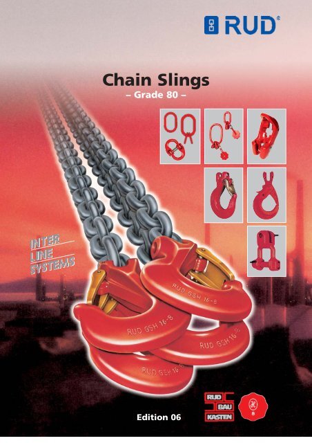
Chain Slings<br />
– Grade 80 –<br />
INTER<br />
LINE<br />
SYSTEMS<br />
Edition 06
The passion of chain<br />
manufacturing!<br />
The round steel chain link<br />
production in Unterkochen<br />
has been running for about<br />
130 years. Producing chains<br />
for lifting, lashing, conveying,<br />
tire protection as well<br />
as snow and off-road chains.<br />
Our headquarters and manufacturing<br />
plant is one of<br />
the most modern chain producing<br />
companies world<br />
wide.<br />
Developed from a small<br />
chain forging company by<br />
the river Kocher, the <strong>RUD</strong><br />
group has stood to the test<br />
of time to become a global<br />
player with approximately<br />
800 motivated employees,<br />
subsidiaries and sales representatives<br />
around the world.<br />
LIFTING MEANS<br />
50 80<br />
Innovation and quality take<br />
first priority at <strong>RUD</strong>. We are<br />
always leading in decisive<br />
developments.<br />
Examples in the lifting and<br />
lashing chains field:<br />
1967: 1. Approval of quality<br />
class 5, H1-5 by the Berufsgenossenschaft<br />
(*employers<br />
liability insurance association).<br />
1972: First chain factory to<br />
gain approval for the quality<br />
class 8, H1-8 by the BG*<br />
Technical Committee ”Steel<br />
and Metal“.<br />
The first idea of a mecano<br />
system from <strong>RUD</strong> – foolproof<br />
connection of the correct<br />
chains and components,<br />
as well as suspension links.<br />
This idea became the standard<br />
at Ruhrkohle RAG (coal<br />
board mining).<br />
1981: The first series of lifting<br />
points type RBS and<br />
RBG with a design factor 4:1<br />
in any direction.<br />
1992: First chain factory to<br />
obtain certification for their<br />
quality assurance system acc.<br />
to DIN/ISO 9001.<br />
1994: First chain factory to<br />
obtain approval of the BG<br />
for their VIP-special quality<br />
with up to 50% higher WLL<br />
than Grade 8.<br />
2002: The first universal lifting<br />
point – called PPS.<br />
The quality assurance system,<br />
certified at <strong>RUD</strong> in<br />
December 1992 by the TÜV-<br />
South West, according to<br />
DIN/ISO 9001, was an important<br />
contribution in order to<br />
meet these requirements<br />
and extends once more the<br />
quality requirements with<br />
regard to the quality assurance<br />
system used by the<br />
company <strong>RUD</strong> during the<br />
past 10 years according to<br />
AQAP 4.<br />
Almost 500 national and<br />
international protective<br />
clauses are the evidence for<br />
our progress.<br />
The well established brand<br />
name <strong>RUD</strong> stands for quality,<br />
technical innovation and<br />
know how. Continuous research<br />
and development has<br />
enabled us not only to produce<br />
products meeting the<br />
highest expectations but<br />
also with consistent quality<br />
standards. Experience, diligence,<br />
ambition and passion<br />
are the virtues we manifest<br />
in order to remain favourite<br />
for our customers. With the<br />
above virtues in mind, <strong>RUD</strong><br />
has successfuly entered a<br />
new century with the trust<br />
and satisfaction of our<br />
customers as our prime<br />
objective for the future.<br />
What are tomorrow`s concepts<br />
This is one of the<br />
questions which <strong>RUD</strong> is trying<br />
to address while facing<br />
the challenge of consistently<br />
providing the best solutions<br />
to our customers.<br />
8 10<br />
Tested by the BG (Employers‘ Liability<br />
Insurance Association)<br />
Iron and Metal Technical Commitee<br />
Norddeutsche Eisen- und Stahl-Berufsgenossenschaft<br />
(North German Iron<br />
and Steel Employers‘ Liability Insurance<br />
Association)<br />
Tested by the BG:<br />
BG vehicle keeping Hamburg<br />
TÜV (Technical Monitoring Association)<br />
tested.<br />
TÜV Rhineland.<br />
2
Clevis System<br />
LIFTING MEANS<br />
<strong>RUD</strong> load pins of quality<br />
class10 can be mounted in<br />
<strong>RUD</strong> grade 80 components<br />
with a stepped borehole.<br />
The dimensional coordination<br />
of the <strong>RUD</strong> clevis system ensures<br />
non-interchangeable, inevitable<br />
assignment of the correct<br />
<strong>RUD</strong> chain gauge.<br />
The BG specifies:<br />
1.) Chain suspensions of quality class 10<br />
must not be used with chains and components<br />
from other manufacturers of quality<br />
class 10.<br />
2.) Suspensions of quality class 8 must not<br />
be combined with components that identifiably<br />
belong to quality class 10.<br />
In brief:<br />
It is forbidden to mix quality classes 8<br />
and 10.<br />
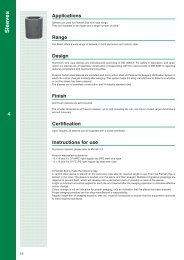
ET round steel chain<br />
corresponds to EN 818-2, quality class 8<br />
Universal system<br />
During assembly and repair,<br />
particular attention must be<br />
paid to ensuring that chains<br />
and components are of the<br />
correct matching dimensions.<br />
Identification and loading<br />
capacity tags must be attached<br />
separately.<br />
Surface: magic black.<br />
Use VIP chains quality class 10 for higher working loading<br />
capacities.<br />
Nominal Load-bearing Weight kg/m Order no.:<br />
thickness capacity<br />
d x t (mm) t<br />
6 x 18 1,12 0,8 0062495<br />
7 x 21 1,5 1,1 0062496<br />
8 x 24 2,0 1,4 0062497<br />
10 x 30 3,15 2,2 0062498<br />
13 x 39 5,3 3,7 0062499<br />
16 x 48 8,0 5,7 0062500<br />
Breaking elongation, magic black, at least 20%.<br />
Ratio of load stress to production test stress to breaking stress =<br />
1 : 2.5 : 4 (200 : 500 : 800 N/mm2).<br />
= mark on fully assembled chain<br />
suspensions.<br />
= mark confirms that the technical<br />
requirements of the European EU<br />
Directives have been fulfilled.<br />
Please comply with the following regulations<br />
without fail:<br />
EN 818/EN 1677/ BGR 500,2.8 – BetrSichV<br />
(Operational Safety Regulations).<br />
We accept no liability for damage arising from<br />
disregard of the standards and regulations<br />
stated in the above instructions.<br />
3
1 strand 2 strand 3 and 4 strand<br />
LIFTING MEANS<br />
Loading<br />
capacity table<br />
in kg<br />
For single and multistrand<br />
sling chains at<br />
various angles of inclination<br />
and symmetrical<br />
loading of the strands<br />
according to EN 818-4.<br />
Now in<br />
quality class<br />
10-VIP<br />
16<br />
20<br />
22<br />
Ask for a VIP<br />
brochure or look<br />
under<br />
www.rud.com!<br />
Inclination- 0° 0–45° 45–60° 0–45° 45–60°<br />
Load factor 1 1,4 1 2,1 1,5<br />
4 Chain diam. (quality class 10-VIP only) (630) (880) (630) (1320) (950)<br />
6 1120 1600 1120 2360 1700<br />
7 1500 2100 1500 3150 2250<br />
8 2000 2800 2000 4250 3000<br />
10 3150 4250 3150 6700 4750<br />
13 5300 7500 5300 11200 8000<br />
16 8000 11200 8000 17000 11800<br />
18 10000 14000 10000 21200 15000<br />
22 16000 22400 16000 33600 25600<br />
26 20000 28000 20000 42000 30000<br />
<br />
Warning! With an asymmetrical load, the loading capacity<br />
is only 50% of the stated value.<br />
<br />
Endless chain (basket)<br />
Choke hitch<br />
<br />
<br />
Now in<br />
quality class<br />
10-VIP<br />
16<br />
20<br />
22<br />
Inclination- 0–45° 45–60° 0–45° 45–60° 0° 0–45° 45–60°<br />
Load factor 1,1 0,8 1,7 1,2 0,8 1,1 0,8<br />
4 Chain diam. (quality class 10-VIP only) (550) (400) (850) (600) (400) (550) (400)<br />
6 1230 900 1900 1350 900 1230 900<br />
7 1650 1200 2550 1800 1200 1650 1200<br />
8 2200 1600 3400 2400 1600 2200 1600<br />
10 3600 2600 5400 3800 2600 3600 2600<br />
13 5700 4000 8500 6000 4000 5700 4000<br />
16 9000 6400 13600 9500 6400 9000 6400<br />
18 11200 8000 17000 12000 8000 11200 8000<br />
22 17600 12800 27200 19200 12800 17600 12800<br />
26 22000 16000 34000 24000 16000 22000 16000<br />
Warning! With an asymmetrical load, the loading capacity<br />
is only 50% of the stated value.<br />
The authorized loading capacity must be reduced if sling chains<br />
Temperature<br />
are used at temperatures above 200°.<br />
Loading capacity in % at chain temperatures of<br />
°C –40 to + 200° C over 200 to 300 °C over 300 to 400 °C<br />
100 % 90 % 75 %<br />
4
T<br />
BK1 suspension head with welded<br />
in, all-round moveable ring fork –<br />
RG –, giving constrained connection<br />
for chain diameter and number<br />
of strands. Complete identification<br />
tag with loading capacity<br />
information.<br />
Connection bolt and locking pin<br />
are pre-assembled.<br />
Also available as<br />
last link (B 1–)<br />
(without identification<br />
tag).<br />
T<br />
C<br />
A<br />
B<br />
LIFTING MEANS<br />
Dimensions correspond to link<br />
form B according to DIN 5688.<br />
Adequate for hooking into small<br />
load hooks on lifting equipment.<br />
For hoist<br />
hooks<br />
Suspension head<br />
1 strand<br />
BK 1<br />
Chain Load. capacity t Name A B C T kg/item. Order. no.<br />
6 1,12 BK 1 – 6 (B1-6) 13 25 54 82 0,5 50 552 (50 608)<br />
8 2,0 BK 1 – 8 (B1-8) 16 34 70 107 0,7 50 556 (50 609)<br />
10 3,15 BK 1 – 10 (B1-10) 18 40 85 131 1,1 50 560 (50 610)<br />
13 5,3 BK 1 – 13 (B1-13) 22 50 115 174 2,0 50 564 (50 611)<br />
16 8,0 BK 1 – 16 (B1-16) 26 65 140 211 3,3 50 568 (50 612)<br />
AK1 suspension head with welded<br />
in, all-round moveable ring<br />
fork – RG –, giving constrained<br />
connection for chain diameter<br />
and number of strands.<br />
Complete identification tag with<br />
loading capacity information.<br />
Connection bolt and locking pin<br />
are pre-assembled.<br />
Suspension head AK 1 can be used<br />
up to crane hook no. DIN 15401.<br />
Size 6– no. 2,5 Size 8– no. 2,5<br />
Size 10– no. 5 Size 13– no. 6<br />
Size 16– no. 8<br />
Also available as last link (A 1–)<br />
(without identification tag).<br />
T<br />
C<br />
A<br />
B<br />
Suspension head<br />
1 strand<br />
AK 1<br />
for standard<br />
crane hooks<br />
Dimensions correspond to<br />
suspension link form A according<br />
to DIN 5688.<br />
Chain Load. capacity t Name A B C T kg/item. Order. no.<br />
6 1,12 AK 1 – 6 (A1-6) 13 60 110 138 0,6 50 469 (50 617)<br />
8 2,0 AK 1 – 8 (A1-8) 16 60 110 147 0,9 50 473 (50 618)<br />
10 3,15 AK 1 – 10 (A1-10) 18 75 135 181 1,4 50 477 (50 619)<br />
13 5,3 AK 1 – 13 (A1-13) 22 90 160 218 2,4 50 481 (50 620)<br />
16 8,0 AK 1 – 16 (A1-16) 26 100 180 250 3,7 50 485 (50 612)<br />
SAK 1 – 140/190/250<br />
SAK 2 – 140/190/250<br />
SAK 3/4 – 140/190/250<br />
On request.<br />
Special<br />
suspension<br />
heads<br />
SAK<br />
For dimensions, see VIP catalog<br />
edition 16.<br />
C<br />
5
LIFTING MEANS<br />
T<br />
C<br />
A<br />
B<br />
BK 2 suspension head with 2 welded<br />
in, all-round moveable ring<br />
forks – RG –, giving constrained<br />
connection for chain diameter<br />
and number of strands. Complete<br />
identification tag with loading<br />
capacity information.<br />
Connection bolt and locking pin<br />
are pre-assembled.<br />
Adequate for<br />
small hoist hooks.<br />
Suspension<br />
head<br />
2 strand<br />
BK 2<br />
Dimensions correspond to link<br />
form B according to DIN 5688.<br />
Chain Load. capacity t Name A B C T kg/item. Order. no.<br />
6 1,6/1,12 BK 2 – 6 13 25 54 82 0,5 50 553<br />
8 2,8/2,0 BK 2 – 8 16 34 70 107 0,9 50 557<br />
10 4,25/3,15 BK 2 – 10 18 40 85 131 1,4 50 561<br />
13 7,5/3,5 BK 2 – 13 22 50 115 174 2,7 50 565<br />
16 11,2/8,0 BK 2 – 16 26 65 140 211 4,4 50 569<br />
Suspension<br />
head<br />
2 strand<br />
AK 2<br />
for standard<br />
crane hooks<br />
T<br />
C<br />
A<br />
B<br />
AK 2 suspension head with 2 welded<br />
in, all-round moveable ring<br />
forks – RG –, giving constrained<br />
connection for chain diameter<br />
and number of strands. Complete<br />
identification tag with loading<br />
capacity information.<br />
Connection bolt and locking pin<br />
are pre-assembled.<br />
Can be used up to crane hook<br />
no. DIN 15401.<br />
Size 6– no. 2,5<br />
Size 8– no. 5<br />
Size 10– no. 6<br />
Size 13– no. 8<br />
Size 16– no. 10<br />
Dimensions correspond to<br />
suspension link form A according<br />
to DIN 5688.<br />
Chain Load. capacity t Name A B C T kg/item.. Order. no.<br />
6 1,6/ 1,15 AK 2 – 6 13 60 110 138 0,74 50 470<br />
8 2,8/ 2,0 AK 2 – 8 18 75 135 172 1,4 50 474<br />
10 4,25/3,15 AK 2 – 10 22 90 160 206 2,3 50 478<br />
13 7,5/ 5,3 AK 2 – 13 26 100 180 238 3,9 50 482<br />
16 11,2/ 8,0 AK 2 – 16 32 110 200 270 6,6 50 486<br />
Suspension<br />
head<br />
4 strand<br />
AK 4<br />
3 strand suspension<br />
heads AK 3-SAK 3,<br />
same order no. as 4<br />
strand suspension<br />
heads. No separate<br />
storage for 3 strand.<br />
T<br />
C<br />
A<br />
B<br />
AK 4 strand suspension head –<br />
technical description as for AK 2,<br />
but with 4 ring forks.<br />
Can be used up to crane hook<br />
no. according to DIN 15401.<br />
Size 6– no. 5<br />
Size 8– no. 6<br />
Size 10– no. 8<br />
Size 13– no.10<br />
Size 16– no. 16<br />
Chain Load. capacity t Name A B C T kg/item. Order. no.<br />
6 2,63/1,7 AK 4 – 6 18 75 135 217 1,6 50 472<br />
8 4,2/3,0 AK 4 – 8 22 90 160 268 3,0 50 476<br />
10 6,7/4,75 AK 4 – 10 26 100 180 311 4,9 50 480<br />
13 11,2/8,0 AK 4 – 13 32 110 200 373 8,9 50 484<br />
16 17,0/11,8 AK 4 – 16 36 140 260 470 14,8 50 488<br />
6
For ET sling chains, design<br />
corresponds to EN 1677-4,<br />
quality class 8.<br />
For connection lock (VS) assembly,<br />
without identification tag –<br />
order separately.<br />
Chain Bezeichnung Load. capacity Dimensions mm Weight Order. no.<br />
mm t d b t kg/item<br />
6 ET-AKO 1–6 1,12 13 60 110 0,36 7985066<br />
7 ET-AKO 1–7 1,5 13 60 110 0,36 7985066<br />
8 ET-AKO 1–8 2,0 16 60 110 0,55 7985067<br />
10 ET-AKO 1–10 3,15 18 75 135 0,82 7985068<br />
13 ET-AKO 1–13 5,3 22 90 160 1,52 7985069<br />
16 ET-AKO 1–16 8,0 26 100 180 2,32 7985070<br />
For ET sling chains, design<br />
corresponds to EN 1677-4,<br />
quality class 8.<br />
For connection lock (VS) assembly,<br />
without identification tag –<br />
order separately.<br />
LIFTING MEANS<br />
ET<br />
suspension<br />
link<br />
1 strand<br />
ET<br />
suspension<br />
link<br />
2 strand<br />
Chain Name Load. capacity t Dimensions mm Weight Order. no.<br />
mm b = 0–45° b = 45–60° d b t kg/item.<br />
6 ET-AKO 2–6 1,6 1,12 13 60 110 0,36 7985066<br />
7 ET-AKO 2–7 2,1 1,5 16 60 110 0,55 7985067<br />
8 ET-AKO 2–8 2,8 2,0 18 75 135 0,82 7985068<br />
10 ET-AKO 2–10 4,25 3,15 22 90 160 1,52 7985069<br />
13 ET-AKO 2–13 7,5 5,3 26 100 180 2,32 7985070<br />
16 ET-AKO 2–16 11,2 8,0 32 110 200 3,92 7985071<br />
For ET sling chains, design<br />
corresponding to EN 1677-4<br />
quality class 8.<br />
For connection lock (VS) assembly,<br />
without identification tag,<br />
order separately.<br />
ET<br />
suspension<br />
link<br />
3/4 strand<br />
Chain Name Load. capacity t Dimensions mm Weight Order. no.<br />
mm b = 0–45° b = 45–60° d b t kg/item.<br />
6 ET-AKO 3/4–6 2,36 1,70 18 75 190 1,2 7985072<br />
7 ET-AKO 3/4–7 3,15 2,25 18 75 190 1,2 7985072<br />
8 ET-AKO 3/4–8 4,25 3,0 22 90 230 2,26 7985073<br />
10 ET-AKO 3/4–10 6,7 4,75 26 100 265 3,42 7985074<br />
13 ET-AKO 3/4–13 11,2 8,0 32 110 315 60,4 7985075<br />
16 ET-AKO 3/4–16 17,0 11,8 36 140 400 10,02 7985076<br />
7
For ET sling chains, design<br />
corresponds to EN 1677-4,<br />
quality class 8.<br />
LIFTING MEANS<br />
A<br />
190<br />
For connection lock (VS) assembly,<br />
without identification tag,<br />
order separately.<br />
ET special<br />
suspension<br />
link<br />
1/2 strand<br />
…with 190 mm<br />
internal width<br />
B<br />
Chain Name Load. capacity t Dimensions mm Weight Order. no.<br />
mm b = 0–45° b = 45–60° A B kg/item.<br />
6 ET-SAKO 1/2–6 1,6 1,12 22x300x190 13x54x25 3,0 7984154<br />
7 ET-SAKO 1/2–7 2,1 1,5 22x300x190 13x54x25 3,0 7984154<br />
8 ET-SAKO 1/2–8 2,8 2,0 26x300x190 16x70x34 4,5 7984155<br />
10 ET-SAKO 1/2–10 4,25 3,15 32x300x190 18x85x40 6,8 7984156<br />
13 ET-SAKO 1/2–13 7,5 5,3 32x300x190 22x115x50 7,8 7984152<br />
16 ET-SAKO 1/2–16 11,2 8,0 36x300x190 26x140x65 11,0 7984153<br />
ET special<br />
suspension<br />
link<br />
3/4 strand<br />
…with 190 mm<br />
internal width<br />
A<br />
190<br />
For ET sling chains, design<br />
corresponds to EN 1677-4,<br />
quality class 8.<br />
For connection lock (VS) assembly,<br />
without identification tag,<br />
order separately.<br />
B<br />
Chain Name Load. capacity t Dimensions mm Weight Order. no.<br />
mm b = 0–45° b = 45–60° A B kg/item.<br />
6 ET-SAKO 3/4–6 2,36 1,7 22x300x190 13x54x25 3,0 7984154<br />
7 ET-SAKO 3/4–7 3,15 2,25 22x300x190 13x54x25 3,0 7984154<br />
8 ET-SAKO 3/4–8 4,25 3,0 26x300x190 16x70x34 4,5 7984155<br />
10 ET-SAKO 3/4–10 6,7 4,75 32x300x190 18x85x40 6,8 7984156<br />
13 ET-SAKO 3/4–13 11,2 8,0 36x300x190 26x140x65 11,0 7984153<br />
ET<br />
identification<br />
tag<br />
– Universal –<br />
With single and multistrand symbols,<br />
without diameter and loading<br />
capacity information, complete<br />
with wire rope connection and alu<br />
grommet, colored red. Stamps<br />
according to loading capacity<br />
information, page 4.<br />
Symbol layout, see top of page 13.<br />
Name Weight kg/item. Order. no.<br />
ET-KZA 0,02 0060587<br />
8
Replacement pin with<br />
securing elementment<br />
D<br />
T<br />
ET connection lock<br />
The universal chain connection<br />
lock. During assembly, attention<br />
must be paid to ensuring that<br />
chains and components are of<br />
the correct matching dimensions.<br />
LIFTING MEANS<br />
A<br />
Universal<br />
System<br />
(not non-interchangeable)<br />
Name<br />
Order. no.<br />
VS-BLZ 5/6 7101780<br />
VS-BLZ 8 7101782<br />
VS-BLZ 10 7101783<br />
VS-BLZ 13 7101784<br />
VS-BLZ 16 7101785<br />
VS-BLZ 18 7101786<br />
VS-BLZ 22 7101787<br />
VS-BLZ 26 7101820<br />
Chain Name Load. capacity t Dimensions mm Weight Order. no.<br />
mm A D T kg/item.<br />
6 ET-VS 5/6 1,12 14 7 40 0,06 0060172<br />
8 ET-VS 8 2,0 18 8 56 0,18 0060173<br />
10 ET-VS 10 3,15 24 11 68 0,3 0060183<br />
13 ET-VS 13 5,30 29 14 88 0,6 0060184<br />
16 ET-VS 16 8,0 35 17 104 1,3 0061256<br />
18 ET-VS 18 10,0 42 21 122 2,2 0061257<br />
22 ET-VS 22 15,0 48 24 146 3,3 0061258<br />
26 ET-VS 26 21,2 66 32 180 5 0061766<br />
Chain Name Load. capacity Dimensions Weight Order. no.<br />
mm t mm kg/item.<br />
A B P<br />
6 ÖH 5/6 1,12 87 24 34 0,26 7982773<br />
8 ÖH 7/8 2,0 102 26 40 0,54 7982775<br />
10 ÖH 10 3,15 122 35 41 0,97 7982777<br />
13 ÖH 13 5,3 154 40 52 1,75 7982779<br />
16 ÖH 16 8,0 185 50 60 2,8 7982781<br />
<br />
B<br />
P<br />
<br />
A<br />
ÖH<br />
eye hooks<br />
Chain Name Load. capacity Dimensions Weight Order. no.<br />
mm t mm kg/item.<br />
A B C D P<br />
6 AÖH 6 1,12 114 15 25 24 33 0,53 7984536<br />
8 AÖH 8 2,0 134 21 29 30 43 0,95 7984537<br />
10 AÖH 10 3,1 170 28 34 40 47 1,90 7984538<br />
13 AÖH 13 5,3 210 32 43 50 61 3,30 7984539<br />
16 AÖH 16 8,0 260 40 57 60 78 7,30 7984540<br />
D<br />
<br />
P<br />
<br />
A<br />
AÖH<br />
automatic<br />
eye hooks<br />
C<br />
B<br />
9
.....................<br />
The original<br />
.....................<br />
proven a million times!<br />
A<br />
Extremely robust design has<br />
proven itself a million times.<br />
Forged safety latch slots into tip<br />
of hook, protecting it against<br />
bending sideways.<br />
LIFTING MEANS<br />
F<br />
B<br />
Ergonomic design, fingerprotecting<br />
actuating hollows.<br />
Granit-Super<br />
hook GSH<br />
T<br />
Triple coiled double leg spring,<br />
stainless.<br />
Wearing edges on both sides –<br />
high bending resistance.<br />
D<br />
Double composite locking sleeve,<br />
easy exchangeable.<br />
C<br />
G<br />
Completely pre-assembled with<br />
load pin and adapter sleeve.<br />
Safety set order no.<br />
53 133<br />
53 134<br />
53 135<br />
53 136<br />
53 137<br />
Chain Load.cap. t Name A B C D F G T kg/item. Order. no.<br />
6 1,12 GSH – 6 27 22 16 20 25 74 75 0,3 53 068<br />
8 2,0 GSH – 8 38 28 20 28 30 98 97 0,8 53 069<br />
10 3,15 GSH – 10 46 36 26 35 35 122 108 1,4 53 070<br />
13 5,3 GSH – 13 58 46 30 37 40 139 126 2,5 53 071<br />
16 8,0 GSH – 16 67 56 36 49 48 164 152 4,1 53 072<br />
AGH<br />
automatic<br />
fork head<br />
hook<br />
(with grooved<br />
load pin)<br />
A<br />
B<br />
Chain Load. Name Dimensions mm Weight Order. no.<br />
mm capacity t A B C D P kg/item.<br />
6 1,12 AGH 6 95 15 25 31 33 0,53 7984530<br />
8 2,0 AGH 8 117 21 29 41 43 0,97 7984531<br />
10 3,15 AGH 10 142 28 34 53 47 2,00 7984532<br />
13 5,3 AGH 13 169 32 43 64 61 3,40 7984533<br />
16 8,0 AGH 16 219 40 57 78 78 7,60 7984534<br />
P<br />
C<br />
Widemouthed<br />
hook/foundry<br />
hook WH<br />
T<br />
A<br />
B<br />
F<br />
D<br />
E<br />
Also known as a foundry or container<br />
hook. With a considerably<br />
wider mouth than the GSH, but<br />
without a securing element.<br />
Only use where unintentional<br />
unhooking is impossible. Does<br />
not comply with EU Machinery<br />
Directive 98/37 EEC I/4.4.1.<br />
Not suitable for transport above<br />
people.<br />
Robust cross-section (dimension<br />
C/B) to withstand higher bending<br />
forces. Wearing edges on both<br />
sides protect the mounted chain<br />
link.<br />
Completely pre-assembled with<br />
load pin and adapter sleeve.<br />
C<br />
Chain Load. cap. t Name A B C D E F T kg/item. Order. no.<br />
6 1,12 WH – 6 30 22 18 30 22 50 88 0,45 7101891<br />
8 2,0 WH – 8 40 29 26 40 29 64 115 0,90 7101892<br />
10 3,15 WH – 10 46 37 30 50 36 76 130 1,70 7101818<br />
13 5,3 WH – 13 51 45 37 64 46 90 168 3,00 7101893<br />
16 8,0 WH – 16 64 56 40 75 56 102 190 5,70 7101621<br />
10
Notice!<br />
A new standard for shortening<br />
elements is in preparation:<br />
pr EN 1677-7.<br />
All <strong>RUD</strong> shortening elements<br />
already comply with all<br />
requirements.<br />
Chain Load. Name Dimensions mm Weight Order. no.<br />
mm capacity t T P kg/item.<br />
8 2,0 VH 7/8 59 10 0,35 7982847<br />
10 3,15 VH 10 74 12 0,80 7982849<br />
13 5,3 VH 13 100 15 1,70 7982851<br />
16 8,0 VH 16 137 18 4,00 7982853<br />
P<br />
T<br />
LIFTING MEANS<br />
VH<br />
shortening<br />
hook<br />
(with grooved load pin)<br />
ET-AKO<br />
AK1<br />
ET-AKO<br />
VS<br />
Possibilities<br />
for using<br />
shortening<br />
elements<br />
VS<br />
3 links<br />
BSEK<br />
VH<br />
max. 60°<br />
<br />
VH<br />
SH<br />
GSH<br />
Optimal combination of max.<br />
mouth width with the smallest<br />
shackle pin.<br />
The turned fork head universal<br />
joint makes it very resistant to<br />
bending.<br />
H<br />
Non-interchangeable<br />
fork shackle<br />
VGSCH<br />
High-tensile, patented design<br />
with integrated safety thread in<br />
the shackle yoke. The bolt brakket<br />
in the shackle is smooth on<br />
both sides. The bolt can be turned.<br />
There is no bending stress in<br />
the thread, it only has a safety<br />
function.<br />
Pre-assembled with locking sleeve.<br />
Secured for long periods by<br />
driving-in a locking sleeve.<br />
T<br />
E<br />
B<br />
A<br />
G<br />
D<br />
C<br />
Chain Load. cap. t Name A B C D E G H T kg/item. Order. no.<br />
6 1,12 V-GSCH 6 17 8 22 10 21 40 28 36 0,15 7983526<br />
8 2,0 V-GSCH 8 21 10 26 12 32 48 39 48 0,26 7983527<br />
10 3,15 V-GSCH 10 27 13 34 16 35 62 45 61 0,65 7983528<br />
13 5,3 V-GSCH 13 33 17 42 20 41 81 59 78 1,35 7983529<br />
16 8,0 V-GSCH 16 38 22 49 24 49 95 69 96 2,5 7983531<br />
11
LIFTING MEANS<br />
Shortening<br />
claw V<br />
(with G-pin)<br />
Shortening claw – V – with flexible self-locking.<br />
Rubber safety device can be retrofitted. Chain-protecting<br />
recessed seating.<br />
No reduction of loading capacity.<br />
The shape and the flexible rubber locking device<br />
provide a double safeguard against the hooked<br />
chain disengaging itself.<br />
Handling the shortening claw<br />
Do not load!<br />
Notice!<br />
A new standard<br />
for shortening elements<br />
is in preparation:<br />
pr EN 1677-7. All<br />
<strong>RUD</strong> shortening<br />
elements already<br />
comply with all<br />
requirements.<br />
Shortening<br />
claw BSEK –<br />
a better –<br />
quicker –<br />
simpler –<br />
claw<br />
New!<br />
Hook in<br />
Hook out<br />
Chain Load. caoacity t Name A B C T kg/item. Order. no.<br />
6 1,12 V – 6 35 35 25 39 0,2 50 648<br />
8 2 V – 8 45 46 34 52 0,5 50 650<br />
10 3,15 V – 10 57 59 42 65 1,0 50 651<br />
13 5,3 V – 13 75 73 55 85 2,0 50 652<br />
16 8 V – 16 92 93 65 107 2,7 50 653<br />
B 2<br />
B 1<br />
T<br />
G<br />
A<br />
Load side<br />
Direction of load.<br />
A further development of the <strong>RUD</strong> shortening claw<br />
V which has proven its worth for decades. Captivefitted<br />
in the continuous chain strand.<br />
No additional chain or coupling parts needed. Can<br />
be fitted on any part of the chain strand.<br />
The chain is ideally supported by the link-shaped<br />
recessed seating – so there is no reduction of the<br />
loading capacity. Conforms to prEN 1677-7.<br />
The robust, spring mounted securing bolt prevents<br />
the hooked chain from disengaging, whether loaded<br />
or unloaded. If the BSEK is not permanently fitted,<br />
please follow the instruction below.<br />
Chain Load. capacity t Name A B 1 B 2 T G kg/item. Order. no.<br />
6 1,12 BSEK – 6 38 34 40 66 38 0,3 79 84073<br />
8 2 BSEK – 8 46 41 52 88 48 0,55 71 02686<br />
10 3,15 BSEK – 10 58 50 64 110 60 1,1 71 02687<br />
13 5,3 BSEK – 13 74 64 86 143 76 2,4 71 02688<br />
16 8,0 BSEK – 16 91 79 105 176 98 4,4 71 01419<br />
Warning!<br />
When shortening<br />
elements are used for<br />
transporting loads, in<br />
most cases the load is<br />
not symmetrical.<br />
(This is caused by a<br />
non-centred centre of<br />
gravity and/or points<br />
of attachment at different<br />
levels). In such<br />
cases, the highest<br />
stress occurs in the single<br />
strand with the<br />
smallest angle of inclination.<br />
The loading<br />
capacity therefore<br />
has to be reduced<br />
by 50 %.<br />
1) 2) 3)<br />
*<br />
B<br />
Load<br />
Fitting:<br />
1) Pull a loose chain strand through the intersecting<br />
slots. Hook the chain into the locking slot at the intended<br />
position. The chain strand is now securely fixated<br />
in the BSEK claw. Preferably fit the third chain link<br />
from the suspension link into the shortening slot.<br />
Handling:<br />
2) With the chain slack, fit the desired link into the<br />
recessed seating, pull the chain down while pressing<br />
the securing bolt. Release by performing these steps in<br />
the reverse order.<br />
Warning!<br />
3) When using the BSEK without a retaining pin lokking<br />
sleeve, ensure that the chain is always completely<br />
hooked into the locking slot (B). When pulling or lifting<br />
the shortened chain ensure that the chain is<br />
always completely hooked into the locking slot (B).<br />
*Do not load a slack, shortened chain.<br />
12
Identification tags, single and<br />
multistrand complying with EN 818,<br />
including open, bendable<br />
link 7 x 21.<br />
LIFTING MEANS<br />
KZA for single and multistrand chains Order. no. 60 442<br />
KZA model without symbols<br />
for internal labeling Order. no. 59 384<br />
Test data tag PDA for marking the<br />
annual check under BGR 500-2.8.<br />
The back is blank for sequential<br />
chain number and/or internal<br />
labeling. Including open, bendable<br />
link 7 x 21.<br />
Identification<br />
tag KZA<br />
Test data tag<br />
PDA<br />
PDA test data tag Order. no. 60 228<br />
<strong>RUD</strong>-RSK System Secutex<br />
made of hardwearing, robustedged<br />
polyurethane.<br />
Edge protection<br />
RSK<br />
Flexible in all directions, can be<br />
slid along the chain by hand.<br />
Diagonal cross-chain distributes<br />
the load evenly. Max. 2 m available.<br />
A<br />
B<br />
L max<br />
Chain Name A B L max Order. no.<br />
6 RSK – 6 27 27 2000 56 033<br />
8 RSK – 8 33 33 2000 56 037<br />
10 RSK – 10 38 38 2000 55 810<br />
13 RSK – 13 50 50 2000 56 038<br />
16 RSK – 16 63 63 2000 on request<br />
Supplied in 1 and 2 m lengths only.<br />
ERFASSEN<br />
RECORDING<br />
<strong>RUD</strong> testing service<br />
Testing =<br />
maintaining value!<br />
BGR<br />
BESCHEINIGEN<br />
CERTIFICATION<br />
<strong>RUD</strong> Chains<br />
30 YEARS<br />
testing<br />
service<br />
VISUAL SICHTPRÜFEN INSPECTION<br />
MEASUREMENT MESSEN<br />
RISSPRÜFEN<br />
CRACK TEST<br />
INSTANDHALTEN<br />
MAINTENANCE<br />
Testing of sling equipment with test certificate<br />
under Operational Safety Regulations BGR 500 - EN 818-EN 1677<br />
Over 300,000 chains<br />
tested in the cause<br />
of safety!<br />
13
LIFTING MEANS<br />
Combi-<br />
Coupler<br />
KK<br />
KK – for chains, suspension links,<br />
eye link.<br />
The loading capacity of the round<br />
loop is not reduced.<br />
Lightweight design with the lowest<br />
height.<br />
Simple, practical mounting and dismounting.<br />
Tested and stamped: complies with<br />
EN 1677.<br />
Patent: 3726738<br />
Load. cap.<br />
Weight Part<br />
Name T A B C D E F<br />
in t in kg no.<br />
1,12 KK 6–8* 25 35 25 9 20 60 5,5 0,15 62029<br />
2,0 KK 8–8* 39 40 28 13 24 71 8 0,25 61575<br />
3,15 KK 10–8 44 54 30 15 28 90 10 0,40 61607<br />
5,3 KK 13–8 55 60 37 21 34 107 13 0,80 61780<br />
* With convex round sling seating.<br />
Combi-<br />
Coupler<br />
adapter<br />
KKA<br />
KKA – for fork head link<br />
Non-interchangeable connection<br />
of all <strong>RUD</strong> clevis connectors in<br />
combination with chains. A shortening<br />
element can be used to<br />
change the length of the round<br />
loop.<br />
Patent: 3726738<br />
Load. cap.<br />
Weight Part<br />
Name T A B C D E F<br />
in t in kg no.<br />
1,12 KKA 6–8 29 35 25 7,2 6 60 0,15 62030<br />
2,0 KKA 8–8 38 40 28 9,7 8 71 0,25 61576<br />
3,15 KKA 10–8 44 54 30 12,2 10 90 0,45 61608<br />
5,3 KKA 13–8 54 60 37 15,7 13 107 0,90 61781<br />
Special<br />
hook<br />
- special load<br />
lifting tackle<br />
- special<br />
components<br />
<strong>RUD</strong> load lifting tackle is manufactured<br />
according to the rules of<br />
the technology, DIN 5428 and<br />
BGR 500. The welding is performed<br />
by qualified welders. Weld<br />
joints are crack-tested. Supplied<br />
with test certificate and load lifting<br />
tackle index card for regular<br />
testing and user information.<br />
Let us know your task specification<br />
or briefly state your technical<br />
data (e.g. loading capacity,<br />
relevant dimensions and function).<br />
14
Chain suspensions must be tested by an expert at<br />
least once every year. Tests may be necessary at<br />
shorter intervals, depending on the operational<br />
conditions. Chains must be subjected to a special<br />
test to ensure that they are crack-free at least every<br />
three years. Chains must also be tested for cracks if<br />
incidents occur which could affect their loading<br />
capacity.<br />
LIFTING MEANS<br />
Visual inspection Finding external faults such as<br />
bent chain links , twisted or dented links. Examining<br />
the condition of the parts and checking<br />
that they have been put together correctly, and<br />
checking the completeness and effectiveness of the<br />
safety devices.<br />
<br />
<br />
Regular<br />
maintenance<br />
and checks<br />
Checking for wear and elongation.<br />
1. Checking the wear on the diameter dm.<br />
2. 2. Checking that the permanent elongation caused<br />
by overloading is not more than 5% of the<br />
division of 3 d.<br />
3. 3. Checking the pitch extension by the wear on<br />
the nominal thickness.<br />
dm = d 1 + d2 0,9 d<br />
2<br />
Accessories: Load hooks must be rejected when<br />
the mouth width has opened by more than 10 %,<br />
or the bottom of the hook has worn by more than<br />
5% or has deep indentations. The same applies to<br />
load hooks that have been bent sideways.<br />
The maximum permissible wear on the diameter of<br />
the G bolt is 10%.<br />
When exchanging accessories, always use new connection<br />
bolts and securing elements (locking sleeves).<br />
Documentation in a chain card index:<br />
The entries in the chain card index provide information<br />
about the user's regular monitoring activities<br />
while using hitching chains. It is essential that<br />
the user has this verification for the factory inspectorate<br />
/Employers' Liability Insurance Association to<br />
prove compliance with the industrial safety / accident<br />
prevention measures(EU Directives 89/655).<br />
Please comply<br />
with the<br />
following<br />
regulations<br />
without fail:<br />
Only use original <strong>RUD</strong> spare parts.<br />
Only the manufacturer may make a surface treatment.<br />
Be aware of the effects of temperature (see<br />
table on page 4).<br />
– Operational Safety<br />
Regulations –<br />
BGR 500/2.8, EN 818,<br />
EN 1677, <strong>RUD</strong> user<br />
information.<br />
We accept no liability<br />
for damage arising<br />
from disregard<br />
of these standards,<br />
regulations or the<br />
above instructions.<br />
15
Lifting points - for bolting -<br />
Maximum transport weight "G" in "tonnes"<br />
with different lifting methods<br />
Thread size<br />
M6-<br />
M150<br />
inch thread<br />
(UNC,...) and special<br />
lengths on<br />
request<br />
PP-S (Vario)<br />
PowerPoint-Star<br />
PP-B (Vario)<br />
PowerPoint-B<br />
PP-VIP (Vario)<br />
PowerPoint-VIP<br />
VLBG Load ring (Vario)<br />
WBG-V<br />
Load ring (Vario)<br />
Number of strands<br />
Direction of load<br />
Type<br />
Thread<br />
PP-S 0,63 t<br />
PP-S 1,5 t<br />
PP-S 2,5 t<br />
PP-S 4 t<br />
PP-S 5 t<br />
PP-S 8 t<br />
VLBG 0,3 t<br />
VLBG 0,63 t<br />
VLBG 1 t<br />
VLBG 1,5 t<br />
VLBG 2,5 t<br />
VLBG 4 t<br />
VLBG 4 t<br />
VLBG 5 t<br />
VLBG 7 t spec.<br />
VLBG 8 t<br />
VLBG 10 t<br />
VLBG 15 t<br />
VLBG 20 t<br />
LBG(3) M16 RS 1t<br />
LBG(3) M20 RS 2t<br />
WBG-V 0,3 t<br />
WBG-V 0,45 t<br />
WBG-V 0,6 t<br />
WBG-V 1,3 t<br />
WBG-V 2 t<br />
WBG-V 3,5 t<br />
WBG-V 5 t<br />
M M M M M M M M M M M M M M M M M M M M M M M M M M M M<br />
12 16 20 24 30 36 8 10 12 16 20 24 27 30 36 36 42 42 48 16 20 8 10 12 16 20 24 30<br />
M<br />
3<br />
1 0° 0,6 1,5 2,5 4 6,7 10 0,3 0,6 1 1,5 2,5 4 4 5 7 8 10 15 20 1 2 0,6 0,9 1,2 2,6 4 7 10<br />
12<br />
2 0° 1,2 3 5 8 13,4 20 0,6 1,2 2 3 5 8 8 10 14 16 20 30 40 2 4 1,2 1,8 2,4 5,2 8 14 20<br />
2<br />
G<br />
1 90° 0,6 1,5 2,5 4 5 8 0,3 0,6 1 1,5 2,5 4 4 5 7 8 10 15 20 1 2 0,3 0,45 0,6 1,3 2 3,5 5<br />
(0,4) (0,6) (0,7) (1,5) (2,5) (4) (6)<br />
6<br />
(7<br />
2 90° 1,2 3 5 8 10 16 0,6 1,2 2 3 5 8 8 10 14 16 20 30 40 2 4 0,6 0,9 1,2 2,6 4 7 10<br />
(0,8) (1,2) (1,5) (3) (5) (8) (12)<br />
1<br />
(1<br />
2<br />
0-<br />
45°<br />
0,8 2,1 3,5 5,6 7,1 11,2 0,4 0,8 1,4 2,1 3,5 5,6 5,6 7 9,8 11,2 14 21 28 1,4 2,8 0,4 0,6 0,8 1,8 2,8 4,9 7<br />
8<br />
(10<br />
2 45- 0,6 1,5 2,5 4 5 8 0,3 0,6 1 1,5 2,5 4 4 5 7 8 10 15 20 1 2 0,3 0,4 0,6 1,3 2 3,5 5<br />
60°<br />
6<br />
(7<br />
asymmetrical<br />
2 0,6 1,5 2,5 4 5 8 0,3 0,6 1 1,5 2,5 4 4 5 7 8 10 15 20 1 2 0,3 0,4 0,6 1,3 2 3,5 5<br />
6<br />
(7<br />
3+4 0- 1,3 3,2 5,3 8,4 10,5 16,8 0,6 1,3 2,1 3,1 5,2 8,4 8,4 10,514,716,8 21 31,5 42 2,1 4,2 0,6 0,9 1,2 2,7 4,2 7,3 10,5<br />
45°<br />
12<br />
(15<br />
3+4 45- 0,9 2,2 3,8 6 7,5 12 0,4 0,9 1,5 2,2 3,7 6 6 7,5 10,4 12 15 22,5 30 1,5 3 0,4 0,6 0,9 1,9 3 5,2 7,5<br />
60°<br />
9<br />
(11<br />
asymmetrical<br />
3+4 0,6 1,5 2,5 4 5 8 0,3 0,6 1 1,5 2,5 4 4 5 7 8 10 15 20 1 2 0,3 0,4 0,6 1,3 2 3,5 5<br />
6<br />
(7<br />
Thread<br />
M M M M M M M M M M M M M M M M M M M M M M M M M M M M<br />
12 16 20 24 30 36 8 10 12 16 20 24 27 30 36 36 42 42 48 16 20 8 10 12 16 20 24 30<br />
M<br />
3<br />
<strong>RUD</strong> Lifting Points<br />
All parts are either 100% crack detected or proof<br />
loaded accord. to EN 1677.<br />
All original bolts from <strong>RUD</strong> are 100% crack detected.<br />
Design factor 4:1 in any direction.<br />
Types VRS, VRM and VLBG have to be adjusted to the<br />
load direction.<br />
<strong>RUD</strong> patented features such as clamping spring (VLBS)<br />
for noise reduction and distance lugs for a perfect root<br />
pass weld increase the ease of use.<br />
<strong>RUD</strong> CD-ROM and slide chart “<strong>RUD</strong>-MULTI-MASTER”<br />
facilitate the correct selection of lifting points.<br />
Low installation height, high dynamic and<br />
static strength.<br />
16
Lifting points - for bolting -<br />
Maximum transport weight "G" in "tonnes"<br />
with different lifting methods<br />
WBG<br />
Load ring<br />
Starpoint VRS<br />
(Vario)<br />
eyebolt<br />
Starpoint<br />
VRM<br />
lifting eye<br />
nut<br />
INOX-<br />
STAR<br />
RS & RM<br />
high-tensile eyebolt/lifting eye nut<br />
RBG/VRBG<br />
Load ring<br />
New!<br />
WBG 6-spec.<br />
WBG 8 t<br />
WBG 8-spec.<br />
WBG 10 t<br />
WBG 10 t<br />
WBG 10-spec.<br />
WBG 15 t<br />
WBG 15 t<br />
WBG 15-spec.<br />
WBG 25 t<br />
WBG 30 t<br />
WBG 35 t<br />
WBG 35-spec.<br />
VRS M8<br />
VRM M8<br />
VRS M10<br />
VRM M10<br />
VRS M12<br />
VRM M12<br />
VRS M16<br />
VRM M16<br />
VRS M20<br />
VRM M20<br />
VRS M24<br />
VRM M24<br />
VRS M30<br />
VRM M30<br />
VRS M36<br />
VRS M42<br />
VRS M48<br />
INOX M12<br />
INOX M16<br />
INOX M20<br />
INOX M24<br />
INOX M30<br />
RS M6<br />
RS M8<br />
RS M10<br />
RS M12<br />
RS M14<br />
RS M16<br />
RS M20<br />
RS M24<br />
RS M30<br />
RS M36<br />
RS M42<br />
RS M48<br />
RBG 3 t<br />
VRBG 10 t<br />
VRBG 16 t<br />
VRBG 30 t<br />
VRBG 50 t<br />
VRBG 80 t<br />
2x 4x 4x 4x 6x 8x<br />
M M M M M M M M M M M M M M M M M M M M M M M M M M M M M M M M M M M M M M M M M M M M M M<br />
33 36 39 42 48 42-52 56 64 56-85 72-76 80-85 90 90-150 8 10 12 16 20 24 30 36 42 48 12 16 20 24 30 6 8 10 12 14 16 20 24 30 36 42 48 16 20 30 36 50<br />
12,512,512,5 16 16 16 25 25 25 35 35 35 35 1 1 2 4 6 8 12 16 24 32 1,2 2,4 3,6 5,2 - 0,4 0,8 1 1,6 3 4 6 8 12 16 24 32 3 10 16 30 50 80<br />
25 25 25 32 32 32 50 50 50 70 70 70 70 2 2 4 8 12 16 24 32 48 64 2,4 4,8 7,2 10,4 - 0,8 1,6 2 3,2 6 8 12 16 24 32 48 64 6 20 32 60 100 160<br />
6 8 8 10 10 10 15 15 15 25 30 35 35 0,4 0,4 0,7 1,5 2,3 3,2 4,5 7 9 12 0,6 1,2 1,8 2,6 - 3 10 16 30 50 80<br />
(7,5) (10) (10) (12,5)(12,5)(12,5) (18) (18) (18) (30) (35) (40) (40)<br />
12 16 16 20 20 20 30 30 30 50 60 70 70 0,8 0,8 1,5 3 4,6 6,4 9 14 18 24 1,2 2,4 3,6 5,2 - 6 20 32 60 100 160<br />
(15) (20) (20) (25) (25) (25) (36) (36) (36) (60) (70) (80) (80)<br />
For this type<br />
of suspension,<br />
we recommend to use either<br />
the »VRS-Starpoint«,<br />
which can be set<br />
in the direction<br />
of force, or PowerPoint<br />
with double ball bearing!<br />
8,4 11,211,2 14 14 14 21 21 21 35 42 49 49 0,56 0,56 1 2,1 3,2 4,5 6,3 9,8 12,616,8 0,8 1,7 2,5 3,6 - 4,2 14 22,4 42 70 112<br />
(10,5) (14) (14) (17,5)(17,5)(17,5)(25,2)(25,2)(25,2) (42) (49) (56) (56)<br />
6 8 8 10 10 10 15 15 15 25 30 35 35 0,4 0,4 0,7 1,5 2,3 3,2 4,5 7 9 12 0,6 1,2 1,8 2,6 - 3 3 10 16 30 50 80<br />
(7,5) (10) (10) (12,5)(12,5)(12,5) (18) (18) (18) (30) (35) (40) (40)<br />
6 8 8 10 10 10 15 15 15 25 30 35 35 0,4 0,4 0,7 1,5 2,3 3,2 4,5 7 9 12 0,6 1,2 1,8 2,6 - 3 8 3 10 16 30 50 80<br />
(7,5) (10) (10) (12,5)(12,5)(12,5) (18) (18) (18) (30) (35) (40) (40)<br />
12,6 16,8 16,8 21 21 21 31,5 31,5 31,5 52,5 63 73,5 73,5 0,8 0,8 1,5 3,1 4,8 6,7 9,4 14,7 18,9 25 1,3 2,5 3,8 5,5 - 25 6,3 21 33,6 63 105 168<br />
(15,7) (21) (21) (26,2)(26,2)(26,2) (38) (38) (38) (63) (73,5) (84) (84)<br />
9 12 12 15 15 15 22,5 22,5 22,5 37,5 45 52,5 52,5 0,6 0,6 1,1 2,2 3,4 4,8 6,7 10,5 13,5 18 0,9 1,8 2,7 3,9 - 10,5 4,5 15 24 45 75 120<br />
(11,2) (15) (15) (18,8)(18,8)(18,8) (27) (27) (27) (45) (52,5) (60) (60)<br />
6 8 8 10 10 10 15 15 15 25 30 35 35 0,4 0,4 0,7 1,5 2,3 3,2 4,5 7 9 12 0,6 1,2 1,8 2,6 - 7 3 3 10 16 30 50 80<br />
(7,5) (10) (10) (12,5)(12,5)(12,5) (18) (18) (18) (30) (35) (40) (40)<br />
2x 4x 4x 4x 6x 8x<br />
M M M M M M M M M M M M M M M M M M M M M M M M M M M M M M M M M M M M M M M M M M M M M M<br />
33 36 39 42 48 42-52 56 64 56-85 72-76 80-85 90 90-150 8 10 12 16 20 24 30 36 42 48 12 16 20 24 30 6 8 10 12 14 16 20 24 30 36 42 48 16 20 30 36 50<br />
CD-ROM for the calculation and<br />
selection of the correct lifting point.<br />
We provide you with the geometric<br />
datas for your design.<br />
New: 3D CAD datas.<br />
www.rud.com<br />
17
VRBK 6,7t<br />
VRBK 10t<br />
G<br />
Weld<br />
seam<br />
Number of strands<br />
1 0°<br />
2 0°<br />
1 90°<br />
2<br />
2<br />
2<br />
2<br />
90°<br />
0-<br />
45°<br />
45-<br />
60°<br />
3+4 0-<br />
45°<br />
3+4<br />
3+4<br />
Direction of load<br />
asymmetrical<br />
45-<br />
60°<br />
asymmetrical<br />
Maximum transport weight "G" in "tonnes"<br />
with different lifting methods<br />
Lifting points - for welding -<br />
18<br />
WPP series<br />
PowerPoint<br />
swivelling<br />
WPP series<br />
PowerPoint<br />
fixed rigid<br />
VLBS VLBS<br />
load Load block ring weldable<br />
weldable<br />
VRBS<br />
eye block Load weldable ring<br />
weldable<br />
VRBSS<br />
eye Load block ring<br />
with adjustment lock<br />
New!<br />
New!<br />
all variants all variants<br />
Type<br />
WPP 0,63 t<br />
WPP 1,5 t<br />
WPP 2,5 t<br />
WPP 4 t<br />
WPP 5 t<br />
WPP 8 t<br />
WPPH 0,63 t<br />
WPPH 1,5 t<br />
WPPH 2,5 t<br />
WPPH 4 t<br />
WPPH 5 t<br />
WPPH 8 t<br />
VLBS 1,5 t<br />
VLBS 4 t<br />
VLBS 6,7 t<br />
VLBS 10 t<br />
VLBS 16 t<br />
LBS(1) RS 0,5 t<br />
LBS(3) RS 1 t<br />
LBS(5) RS 2 t<br />
VRBS 4 t<br />
VRBS 6,7 t<br />
VRBS 10 t<br />
VRBS 16 t<br />
VRBS 30 t<br />
VRBS 50 t<br />
1 0°<br />
2 0°<br />
G<br />
1 90°<br />
2<br />
90°<br />
2<br />
0-<br />
45°<br />
2<br />
45-<br />
60°<br />
2<br />
3+4 0-<br />
45°<br />
3+4<br />
3+4<br />
asymmetrical<br />
45-<br />
60°<br />
asymmetrical<br />
Number of strands<br />
VRBK<br />
eye block Load for ring edges<br />
for edges<br />
New!<br />
New!<br />
Direction of load<br />
VRBSS 6,7 t<br />
VRBSS 10 t<br />
VRBSS 16 t<br />
VRBK 4 t<br />
0,6 1,5 2,5 4 6,7 10 0,6 1,5 2,5 4 6,7 10 1,5 4 6,7 10 16 0,5 1 2 4 6,7 10 16 30 50<br />
6,7 10 16 4 6,7 10<br />
1,2 3 5 8 13,4 20 1,2 3 5 8 13,4 20 3 8 13,4 20 32 1 2 4 8 13,4 20 32 60 100<br />
13,4 20 32 8 13,4 20<br />
0,6 1,5 2,5 4 5 8 0,6 1,5 2,5 4 5 8 1,5 4 6,7 10 16 0,5 1 2 4 6,7 10 16 30 50<br />
6,7 10 16 4 6,7 10<br />
1,2 3 5 8 10 16 1,2 3 5 8 10 16 3 8 13,4 20 32 1 2 4 8 13,4 20 32 60 100<br />
13,4 20 32 8 13,4 20<br />
0,8 2,1 3,5 5,6 7,1 11,2 0,8 2,1 3,5 5,6 7,1 11,2 2,1 5,6 9,38 14 22,4 0,7 1,4 2,8 5,6 9,38 14 22,4 42 70<br />
9,38 14 22,4 5,6 9,38 14<br />
0,6 1,5 2,5 4 5 8 0,6 1,5 2,5 4 5 8 1,5 4 6,7 10 16 0,5 1 2 4 6,7 10 16 30 50<br />
6,7 10 16 4 6,7 10<br />
0,6 1,5 2,5 4 5 8 0,6 1,5 2,5 4 5 8 1,5 4 6,7 10 16 0,5 1 2 4 6,7 10 16 30 50<br />
1,3 3,2 5,3 8,4 10,5 16,8 1,3 3,2 5,3 8,4 10,5 16,8 3,15 8,4 14,1 21 33,6 1,05 2,1 4,2 8,4 14,1 21 33,6 63 105<br />
0,9 2,2 3,8 6 7,5 12 0,9 2,2 3,8 6 7,5 12 2,25 6 10,1 15 24 0,75 1,5 3 6 10,1 15 24 45 75<br />
0,6 1,5 2,5 4 5 8 0,6 1,5 2,5 4 5 8 1,5 4 6,7 10 16 0,5 1 2 4 6,7 10 16 30 50<br />
6,7 10 16 4 6,7 10<br />
14,1 21 33,6 8,4 14,1 21<br />
10,1 15 24 6 10,1 15<br />
6,7 10 16 4 6,7 10<br />
Weld<br />
seam<br />
<br />
<br />
HV HV HV HV HV HV HV HV HV HV HV HV HV HV HV HV HV HV HV HV HV HV<br />
3,5 4,5 3+4,5 3+5 3+8 3+10 3,5 4,5 3+5 3+6 3+8 3+10 5+3 8+3 12+4 16+4 25+6 5+3 8+3 12+4 4+3 5,5+3 8,5+4 8,5+4 15+4 25+8<br />
HV HV HV HV HV HV<br />
5,5+3 6+4 8,5+4 4+3 5+3 8+3
®<br />
1-<br />
▲<br />
®<br />
®<br />
Benutzerinformation<br />
für <strong>RUD</strong>-Anschlagketten<br />
Anleitungen für sichere Handhabung und Vermeidung von Gefährdungen.<br />
...Güteklasse 10 ...Güteklasse 8<br />
Anschlag- und Zurrmittel<br />
– Güteklasse 10 –<br />
Edition 16<br />
Anschlagketten<br />
INTER<br />
LINE<br />
SYSTEMS<br />
– Güteklasse 8 –<br />
Edition 06<br />
Ensprechend Maschinenrichtlinie EG-RL 98/37 EG,<br />
Entsprechend EG-Arbeitsmittel Benutzungsrichtlinie,<br />
Berufsgenossenschaftliche Regel BGR 500, EN 818, EN 1677.<br />
AUSWAHL/<br />
SYSTEM<br />
BAU<br />
KASTEN<br />
GEBRAUCH<br />
INSPEKTION/<br />
PRÜFUNG<br />
INSTANDHALTUNG/<br />
REPARATUR<br />
DOKUMENTATION<br />
Protractor<br />
90 x 120 mm.<br />
The chain thickness is select<br />
according to the weight of<br />
the load, taking into account<br />
the measured inclination<br />
angle, quality class 10-VIP<br />
and quality class 8.<br />
Tragfähigkeit in »t«<br />
von ein- und mehrsträngigen Anschlagketten<br />
bei verschiedenen Neigungswinkeln<br />
bei symmetrischer BelastungderStränge<br />
3-4-Strang<br />
60° 45°<br />
<strong>RUD</strong><br />
order no.<br />
7991453<br />
10<br />
Prüfen von Ketten<br />
und Bauteilen<br />
entsprechend<br />
EN 818<br />
BGR 500<br />
<br />
30<br />
24<br />
Güteklasse 10<br />
15<br />
10<br />
6,0<br />
Bei Anwendung im Schnürgang oder als Kranzkette ist die Tragfähigkeit um 20% zu reduzieren!<br />
2-Strang<br />
45°<br />
20<br />
16<br />
3-4-Strang<br />
3,8<br />
2,3<br />
1<br />
t<br />
t<br />
t<br />
t<br />
0,9<br />
2,1<br />
3,5<br />
5,6<br />
9,5<br />
14<br />
22,4<br />
t Ø<br />
Achtung: Bei unsymmetrischer Belastung =Tragfähigkeit nur 50% des angegebenen Wertes!<br />
<strong>RUD</strong>-<br />
Anschlagmittel<br />
Neigungs-<br />
10<br />
<br />
6,7<br />
42<br />
4,0<br />
33,6<br />
45° 0°<br />
<strong>RUD</strong>-Anschlagpunkte<br />
schraubbar/schweißbar<br />
www.rud.com<br />
<br />
21<br />
2,5<br />
14<br />
1,5<br />
8,4<br />
0,6<br />
5,3<br />
3,2<br />
1,3<br />
28<br />
2-Strang<br />
0,6<br />
1,5<br />
2,5<br />
4,0<br />
6,7<br />
10<br />
4<br />
6<br />
8<br />
16<br />
20<br />
10<br />
13<br />
16<br />
Strang<br />
0°<br />
20<br />
22<br />
Kette<br />
mm<br />
Ø<br />
...in<br />
preparation!<br />
<strong>RUD</strong> order no. 7101019<br />
Warning notice!<br />
Follow the instruction<br />
manual for<br />
the relevant sling<br />
chains!<br />
Loading<br />
capacity<br />
poster<br />
420 x 625 mm.<br />
VIP quality class 10<br />
and quality class 8.<br />
TS 44319 MediaScript/<strong>RUD</strong>-Katalog – Gü-M-7100966 – englisch 3/2.11.2006<br />
Lifting and Lashing Systems<br />
– Special Grade 10 –<br />
LIFTING MEANS<br />
LIFTING MEANS<br />
®<br />
Quality class 10-VIP modular<br />
system – the best in the long run.<br />
New!<br />
3D CAD<br />
Data<br />
<strong>RUD</strong><br />
order<br />
no. 7104459.<br />
Gü-M/7100966/BA/09.06/M Subject to technical alternations.<br />
Edition 16<br />
Mit freundlicher Genehmigung der MAN TURBO AG.<br />
Please ask for the<br />
special VIP sling<br />
chains brochure.<br />
LIFTING MEANS<br />
®<br />
Quality class 10-VIP lashing chains<br />
have 30% more lashing strength LC than quality class 8<br />
– you won't find a better one –<br />
90° 90° 90°<br />
90°<br />
80° 80°<br />
70° 70°<br />
80°<br />
80°<br />
<br />
60° 60°<br />
50° 50°<br />
45° 45°<br />
40° 40°<br />
70°<br />
30° 30°<br />
70°<br />
20° 10° 0° 10° 20°<br />
60°<br />
60°<br />
<br />
50° 45° 40° 30° 20° 10° 0° 10° 20° 30° 40° 45° 50°<br />
Zur Winkelermittlung , diese Kante an Kettenstrang anlegen!<br />
Zur Winkelermittlung,<br />
Winkelmesser parallel<br />
zur Außenkante Ladefläche<br />
(Fahrer- bzw.<br />
Beifahrerseite)<br />
anlegen!<br />
▲<br />
Zur Winkelermittlung ,<br />
Winkelmesser parallel<br />
zur Außenkante Ladefläche<br />
(Fahrer- bzw.<br />
Beifahrerseite)<br />
anlegen!<br />
With lashing<br />
multimaster<br />
and calculation<br />
CD.<br />
»MULTI-ZURRMASTER«<br />
gssicherung auf Straßenfahrzeugen<br />
700/02, prEN 12195-1<br />
VIP(-Kette)!<br />
ZURRMITTEL<br />
Ladungsgewicht „t“<br />
Reibbeiwert <br />
19
Tradition in Leadership<br />
<strong>RUD</strong> Ketten<br />
Rieger & Dietz GmbH u. Co. KG<br />
Friedensinsel<br />
73432 Aalen/Germany<br />
Telefon: +49 7361 504-1371-1314-1527<br />
Telefax: +49 7361 504-1460<br />
info@rud.com<br />
www.rud.com<br />
German<br />
engineering<br />
from the heart<br />
of Europe! 7<br />
9 93<br />
✈<br />
3<br />
70<br />
70<br />
5<br />
6<br />
81<br />
81<br />
7<br />
6<br />
3<br />
✈<br />
73<br />
9<br />
9<br />
6<br />
3<br />
93<br />
✈<br />
8<br />
9<br />
93<br />
81<br />
7<br />
✈<br />
8<br />
94<br />
Further <strong>RUD</strong> products for diverse<br />
applications:<br />
■ Materials handling systems<br />
■ Load lifting tackle<br />
■ Hoisting chains