Volume 6, Issue 1 - Naval Sea Systems Command - The US Navy
Volume 6, Issue 1 - Naval Sea Systems Command - The US Navy
Volume 6, Issue 1 - Naval Sea Systems Command - The US Navy

You also want an ePaper? Increase the reach of your titles
YUMPU automatically turns print PDFs into web optimized ePapers that Google loves.
SEAFRAME<br />
Carderock Division Publication<br />
2010 • <strong>Volume</strong> 6 • <strong>Issue</strong> 1<br />
SEAFRAME Staff<br />
Executive Editor<br />
Kevin Sykes<br />
Managing Editor<br />
William Palmer<br />
Art Director<br />
Gloria Patterson<br />
Layout<br />
Laura Phenicie<br />
Writing/Editing<br />
William Palmer<br />
Yvonne Watson<br />
SEAFRAME is the official publication<br />
of the <strong>Naval</strong> Surface Warfare<br />
Center, Carderock Division. It is<br />
published with appropriated funds in<br />
accordance with NAVSO-P35.<br />
Any views and opinions expressed<br />
are not necessarily those of the<br />
Department of the <strong>Navy</strong>.<br />
Address correspondence and<br />
submissions to SEAFRAME,<br />
Congressional and<br />
Public Affairs Branch,<br />
Code 3830<br />
9500 MacArthur Blvd.<br />
West Bethesda, MD 20817-5700<br />
Attn: Kevin Sykes.<br />
Fax to 301-227-4428 (DSN 287)<br />
or email kevin.sykes@navy.mil<br />
<strong>The</strong> SEAFRAME staff reserves the right<br />
to edit or rewrite all submissions.<br />
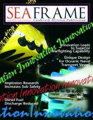
<strong>The</strong> front cover suggests the various efforts the<br />
<strong>Navy</strong> is involved with to make our fleet missioncapable<br />
while addressing lowering the costs<br />
associated with creating and maintaining that<br />
fleet. <strong>The</strong> "313" symbolizes our commitment<br />
to a 313-ship <strong>Navy</strong>, keeping our capabilities<br />
high and our acquisition and sustainment costs<br />
low. This issue of SEAFRAME is devoted to<br />
highlighting the efforts of Carderock Division's<br />
superlative workforce of men and women to<br />
meet head-on the challenges of building an<br />
affordable fleet now and into the future.<br />
U.S. <strong>Navy</strong> photos.<br />
Cover design by Gloria Patterson,<br />
NSWC Carderock Division.<br />
TABLE OF CONTENTS<br />
FROM THE TOP<br />
Inside<br />
Front<br />
Cover Building an Affordable Future Fleet<br />
B<strong>US</strong>INESS<br />
3 Pilot Program Initiatives<br />
C<strong>US</strong>TOMER ADVOCACY<br />
5 <strong>The</strong> Littoral Mine Warfare<br />
Program Executive Office<br />
CORE EQUITIES<br />
8 Responding to the Challenges<br />
of Re-supply at <strong>Sea</strong><br />
12 Environmental Monitoring<br />
and Operator Guidance<br />
System and Channel Analysis<br />
and Depth Evaluation Tool<br />
18 Ship to Shore Connector<br />
20 Accelerated Insertion of Materials<br />
22 Plastic Waste Processor<br />
24 Computational Research and<br />
Engineering for Acquisition Tools<br />
and Environments<br />
26 Signature Decomposition<br />
Analysis<br />
TECHNOLOGY AND INNOVATION<br />
30 High Temperature Degaussing<br />
SEAFRAME<br />
3
SEAFRAME<br />
4<br />
FROM THE TOP<br />
BUILDING AND AFFORDABLE FUTURE FLEET (Continued on page 2)<br />
<strong>The</strong> second is to facilitate efficient and cost effective solutions by providing program decision-makers with<br />
more technical options and advising them on any associated technical risks.<br />
Carderock Division supports the <strong>Navy</strong> by providing technical capability in naval architecture and marine<br />
engineering for both the current and future fleet. To enhance the <strong>Navy</strong>’s future war fighting capabilities we have been<br />
working on cost-effective solutions that will help ships meet the increased power requirements of their mission loads.<br />
Adapting commercial developments such as using insulated bus pipe (IBP) for shipboard transmission lines could<br />
save the <strong>Navy</strong> time, money, weight, and space. In addition, IBP holds the potential for new <strong>Navy</strong> electrical distribution<br />
system designs that can reduce vulnerability, enhance survivability, and reduce ship fabrication costs.<br />
We are also looking at innovative testing methods and analysis that can achieve significant cost savings for the<br />
<strong>Navy</strong>. For example, acoustic target strength signature control technologies and analysis methodologies have evolved to<br />
the development of a prediction tool and a real-world measurement scenario that was used to certify key performance<br />
parameters for a submarine class operational requirements document. <strong>The</strong> development and use of this too–Target<br />
Strength Predictive Model and the accompanying real-world verification technique resulted in significant cost savings<br />
to an acquisition submarine program office and should lead to significant cost avoidance for future <strong>Navy</strong> programs.<br />
Two other examples of our affordability efforts can be found in our composite materials research to increase<br />
the payload and range of future <strong>Navy</strong> ships and our investigation into methods to mitigate downtime and asset<br />
degradation due to corrosion. We are also trying to find answers to some of the environmental challenges that create<br />
work and increase costs.<br />
You will read a lot more in this issue of SEAFRAME about our efforts to support Vice Adm. McCoy’s<br />
direction of Building an Affordable Future Fleet. Obviously, we cannot cover all of our endeavors in this one magazine,<br />
but affordability is and will continue to be a Carderock Division thrust. We are making significant progress, and we will<br />
continue to move forward.<br />
Above: <strong>The</strong> amphibious command ship <strong>US</strong>S Blue Ridge (LCC 19) is underway in the Pacific Ocean. U.S. <strong>Navy</strong> photo.
PILOT PROGRAM<br />
INITIATIVES<br />
B<strong>US</strong>INESS<br />
Supporting the Strategic Business Plan<br />
by Offering Customers Cost Reduction Options<br />
By<br />
Vincent<br />
Wagner<br />
In July 2008, Vice Adm. Kevin<br />
McCoy called upon the Warfare Centers<br />
to support <strong>Naval</strong> <strong>Sea</strong> <strong>Systems</strong> <strong>Command</strong><br />
(NAVSEA) Strategic Business Plan goal<br />
of lowering costs by identifying cost<br />
reduction options for customer approval.<br />
<strong>The</strong> intent was to develop an overall methodology that<br />
would be applicable to most future task statements. <strong>The</strong><br />
vice admiral established two pilot programs relating to<br />
our existing task statements, one of which is the Hull,<br />
Mechanical and Electrical (HM&E) Pilot, under the<br />
direction of Marc Magdinec, Warfare Center Surface<br />
Senior Executive.<br />
NAVSEA’s concern with the current task<br />
statements was that the broad language used by Program<br />
Executive Officer and Program Managers, Directorates, and<br />
the Warfare Centers might not be immediately transparent<br />
in defining the tasks required to achieve the overall program<br />
goal. <strong>The</strong>y also expressed the desire for more clarity<br />
between the technical point of contact and the customer<br />
on specific deliverables. While they recognized the current<br />
approach provides both the program manager and Warfare<br />
Centers needed flexibility during task execution, they<br />
believed that the process could create inefficiencies and<br />
encouraged an unnecessary level of effort. Furthermore,<br />
they were concerned that under the current system<br />
customers had limited ability to assess the risk and impact<br />
of not performing or delaying the execution of work.<br />
<strong>The</strong> initial objective of the pilot program was to<br />
get immediate financial savings that would generate funds<br />
for other navy priorities. Subsequent to the introduction<br />
of the pilot, NAVSEA determined that redirection of these<br />
funds was not a viable option without Congressional level<br />
approval. It was decided that in most cases, the savings<br />
identified would be turned over to the sponsor for reissue to<br />
higher priority tasking. Although the ultimate direction of<br />
the money was changed, it did not alter the initial concept or<br />
the pilot or our approach.<br />
Magdinec, with agreement from the appropriate<br />
sponsor leadership, narrowed our HM&E Pilot down to<br />
SEAFRAME<br />
specific areas, focusing on the DDG 1000 Program and<br />
In-service Ships. To help organize information, we received<br />
support from Program Customer Advocates Bill Merryman,<br />
Joe Amadoro, and Dave Rich. D.J. Benedetti, the Lead<br />
Customer Advocate for Surface, was also involved in the<br />
pilot, responsible for coordinating the SEA 05 efforts that<br />
didn’t fall under Joe or Dave, and helping to coordinate the<br />
overall package. We also received a lot of help from the<br />
Directorates within the Carderock Division.<br />
As the first step of the pilot, Magdinec formed a<br />
team consisting of personnel from SEA 05, SEA 21, and<br />
PEO SHIPS, along with Warfare Center personnel from<br />
Carderock, Dahlgren, and Panama City Divisions. Together,<br />
we reviewed the Task Planning Sheet (TPS), the formal<br />
document used by the sponsors to document tasking. This<br />
review covered the statement of work, funding levels for<br />
both the current and out years, deliverables, key personnel,<br />
signatories, and other information relevant to the customer.<br />
We first examined the documents for clarity and, where<br />
necessary, edited them to assure some standardization.<br />
We also reviewed the facts pertaining to funding, delivery,<br />
monetary amounts, deliverables, milestones and the<br />
POA&M to determine if they were accurate and met<br />
program requirements. For the most part, all information<br />
was satisfactory or simply required minor adjustments. <strong>The</strong><br />
TPSs are a top level document that roles up information<br />
from various meetings, discussions and other documents,<br />
into a single source for all information. When we reviewed<br />
these documents, we all realized that to someone not<br />
intimately familiar with the specific tasks, the documents<br />
could be confusing if all sections were not filled in, so we<br />
made an effort to make sure the TPSs were complete.<br />
This effort certainly made the documents more<br />
standardized and clear to those not regularly involved in the<br />
tasking, but it did not prove to be a tool for significant cost<br />
savings. One significant benefit was it allowed the three<br />
sponsors to review each others TPSs, and they gained an<br />
appreciation for tasking ongoing in the other areas that effect<br />
their tasking.<br />
PILOT PROGRAM INITIATIVES (Continued on page 6)<br />
5
SEAFRAME<br />
6<br />
B<strong>US</strong>INESS<br />
Supporting the Strategic Business Plan<br />
by Offering Customers Cost Reduction Options<br />
PILOT PROGRAM INITIATIVES (Continued from page 5)<br />
Our next step was more productive in generating<br />
some savings. In this phase of the HM&E Pilot we<br />
developed an impact statement for every task based on<br />
5, 10, and 15 percent funding reductions. <strong>The</strong>se impact<br />
statements could be alternative ways to accomplish tasks<br />
and/or increasing risk on a task by decreasing some minor<br />
subtasking. This effort was really no different from the<br />
approach we took when originally developing the tasks, the<br />
benefit gained here was for some tasking, new information<br />
was now available that helped us better understand<br />
the problem statement and find different solutions for<br />
addressing the issues. We also were able to discuss with the<br />
sponsors the current return on investments for tasking to see<br />
if it might make sense to eliminate the tasking because of<br />
a projected low return. In other cases, we were far enough<br />
along in the work to realize some tasks were no longer<br />
necessary, or could be reduced in scope. <strong>The</strong>se evaluations<br />
were not entirely new to us they are part of our day-to-day<br />
communication with our customers. However, under the<br />
HM&E Pilot we used a more structured approach with the<br />
objective of providing the Program Manager with more<br />
information to make an informed decision about the cost/<br />
risk benefits of each undertaking.<br />
Of course, any decision is not easy. <strong>The</strong>se<br />
documents are developed in the spring and through the<br />
summer time frame and as events unfold, certain predictions<br />
have to be changed. For example, we may think we are<br />
going to do an installation on a certain ship at a certain time,<br />
only to have the ship’s schedule change, rendering the ship<br />
unavailable. Alternatively, the ship may be available, but<br />
our testing may reveal something unanticipated requiring<br />
a change to the original plans. In other words, the work<br />
we do cannot simply be approached like an assembly<br />
line. A host of things can happen that will undo our most<br />
carefully thought out tasking statement. Thus, in making<br />
their decisions, the customer must look at probabilities that<br />
cannot even be imagined at the time of tasking. One way we<br />
currently mitigate some of the unexpected contingencies is<br />
through frequent meetings between the program manager<br />
and technical personnel. In these meetings we not only<br />
reassess the status of ongoing work, we also discuss<br />
the internal reallocation of resources from a task that is<br />
performing better than expected to one that is not.<br />
After completing our HM&E Pilot risk assessment,<br />
we presented our findings to the sponsors. $11.8M in savings<br />
was identified across all sponsors from all Warfare Centers,<br />
$5.6M of which was savings related to Carderock Division<br />
tasking. Most of the savings arose by increasing risk. Some of<br />
it occurred because we were further along in the work and had<br />
more ideas about what we could do to reduce costs. And, in a<br />
few cases, we found a way to reduce the costs by doing things<br />
differently or clarifying specific tasking.<br />
One of the more important results is that we<br />
were able to show NAVSEA leadership, the sponsors,<br />
and ourselves that the Task Planning Sheets are fairly<br />
informative documents when they are filled out completely.<br />
We were also able to show that Carderock Division’s<br />
working relationship with the sponsors is very good. <strong>The</strong><br />
sponsors agreed that future information sharing between<br />
sponsors is something they are interested in because it will<br />
improve their knowledge of what is being done on other<br />
tasks and provide them with additional information to<br />
improve their programs and mitigate risks.<br />
Lead, Customer Advocate<br />
Vincent Wagner<br />
vincent.wagner@navy.mil<br />
215-897-8492 (DSN 443)
As part of the change in Warfare<br />
Center (WC) management, customer<br />
advocates (CAs) were realigned to<br />
serve as principal agents of the five WC<br />
National Workload Managers (NWMs).<br />
<strong>The</strong>se advocates provide overall<br />
project management and oversight for all projects under<br />
their cognizance at their divisions. <strong>The</strong>y are responsible<br />
for maintaining a national perspective, advocating for their<br />
assigned customers, and under the direction of the NWM,<br />
assuring work is assigned to the appropriate WC sites.<br />
<strong>The</strong> customer advocates are also responsible for<br />
managing the WC division relationships with sponsors,<br />
program offices, and foreign national contacts, especially<br />
in the case of foreign military sales. <strong>The</strong>y negotiate cost<br />
proposals and tasking for all program work performed<br />
at their division and collaborate with other WC division<br />
sites on program-specific initiatives and proposals. In<br />
support of the commander and<br />
technical director of the <strong>Naval</strong><br />
Surface Warfare Center (NSWC),<br />
Carderock Division, these advocates<br />
work closely with technical project<br />
managers and engage in meaningful<br />
cost, schedule, and performance<br />
discussions with the customers.<br />
In the case of Unmanned<br />
Vehicle (UVs) acquisition engineering<br />
support within the Division, Dave<br />
Cleland is assigned as the CA for the<br />
Program Executive Office Littoral<br />
Mine Warfare (PEO LMW). In this<br />
position, he speaks on behalf of<br />
the Division regarding workload<br />
customer advocacy<br />
Carderock Division CAs Help PEO LMW<br />
“Build an Affordable Future Fleet”<br />
By<br />
Ron Warwick,<br />
Dave Cleland,<br />
and<br />
William Palmer<br />
Right: An MCM <strong>US</strong>V.<br />
Photo courtesy of NSWC<br />
Panama City and PMS 403.<br />
THE LITTORAL MINE<br />
WARFARE PROGRAM<br />
EXECUTIVE OFFICE<br />
commitments, cost, schedule, and performance status.<br />
In cases where multiple WCs are needed to support a<br />
program, the CAs from each WC collaborate to develop<br />
one integrated WC proposal. In the area of UVs, PEO<br />
LMW provides numerous opportunities for Carderock<br />
Division to leverage its technical capabilities to support<br />
our focus area of “Building an Affordable Future Fleet.”<br />
PMS 403 is the Unmanned Maritime <strong>Systems</strong><br />
Program Office under PEO LMW. Two of the UV projects<br />
under PMS 403 that Carderock Division supports are the<br />
Mine Countermeasures (MCM) Unmanned Surface Vehicle<br />
(<strong>US</strong>V) and Anti-Submarine Warfare (ASW) <strong>US</strong>V.<br />
<strong>The</strong> MCM <strong>US</strong>V task for Carderock involved the<br />
design, development, integration, test, and delivery of<br />
the <strong>US</strong>V platform with integrated <strong>Command</strong> and Control<br />
(C2). Carderock also supported the integration and test<br />
of the MCM Payload system along with the associated<br />
SEAFRAME<br />
WARFARE PROGRAM EXECUTIVE OFFICE (Continued on page 8)<br />
7
SEAFRAME<br />
8<br />
customer advocacy<br />
WARFARE PROGRAM EXECUTIVE OFFICE (Continued from page 7)<br />
ship-to-<strong>US</strong>V communications system. <strong>The</strong> payload is a<br />
MCM sweep system which includes primary components<br />
such as a power generation unit, winch, payload control<br />
system, and the towed magnetic/acoustic sweep. <strong>The</strong>re are<br />
currently two Engineering Development Models (EDMs)<br />
delivered, undergoing testing and integration with the<br />
Littoral Combat Ship.<br />
<strong>The</strong> working MCM <strong>US</strong>V team consists of NSWC<br />
Carderock Division as the <strong>US</strong>V Craft Technical and<br />
Interface/Integration lead, NSWC Panama City Division<br />
as the Mission Package System Integration and MCM<br />
payload lead, and SPAWAR Charleston, as the C2 lead.<br />
Carderock Division provides technical expertise for the<br />
<strong>US</strong>V primarily from Carderock’s Combatant Craft and the<br />
Marine and Aviation Divisions. This has been an extremely<br />
successful team arrangement that leverages and highlights<br />
the core technical capabilities and knowledge areas of each<br />
WC. <strong>The</strong> CAs from Carderock and Panama City Divisions<br />
have worked closely together with PMS 403 to coordinate<br />
the tasking and funding between the WCs to meet cost,<br />
schedule, and performance agreements. <strong>The</strong> recent successful<br />
completion of the fully unmanned MCM mission profile<br />
scenario testing at Panama City Division highlights the strong<br />
integrated project team support and technical expertise of the<br />
WC collaborative approach for this program.<br />
<strong>The</strong> ASW <strong>US</strong>V Carderock program tasking has<br />
involved evaluating the existing ASW Craft and providing<br />
safety review and program oversight for the NAVSEA<br />
Technical Authority Warrant Holder for combatant craft<br />
and boats. Combatant Craft Division personnel conducted<br />
rough water testing, physical craft audits, documentation<br />
reviews, and supported the numerous ASW <strong>US</strong>V test events.<br />
Under the current construct, <strong>Naval</strong> Undersea Warfare<br />
Center, Newport Division is the team lead for the ASW <strong>US</strong>V<br />
program with collaborative site support from Carderock<br />
Division and several other WC divisions.<br />
<strong>The</strong> ASW <strong>US</strong>V system currently consists of two<br />
Engineering Development Model (EDM) <strong>US</strong>Vs craft capable<br />
of carrying mission-dependent ASW payloads. Operational<br />
scenarios may involve both EDM <strong>US</strong>Vs with complementary<br />
payloads operating simultaneously in a coordinated approach<br />
or as a single EDM <strong>US</strong>V and payload coordinated with<br />
another mission platform and associated sensor.<br />
<strong>The</strong> WC CAs worked with the site Technical Project<br />
Managers (TPMs) and PMS 403 Program Manager (PM)<br />
to provide a consolidated project tasking plan, budget, and<br />
schedule. Iterative CA working meetings during the budgeting<br />
process with Carderock Division and NUWC TPMs facilitated<br />
an executable approach within the PM’s fiscal constraints.<br />
<strong>The</strong> CAs from both WCs also enabled resolution of project<br />
concerns and issues by facilitating sponsor and project lead<br />
communications and by providing potential solutions.<br />
Above: MCM <strong>US</strong>V conducting sweep operations.<br />
Photo courtesy of NSWC Panama City and PMS 403.<br />
Above: MCM <strong>US</strong>V in transit.<br />
Photo courtesy of NSWC Panama City and PMS 403.<br />
In both of these <strong>US</strong>V projects the CAs from<br />
three WC sites have worked closely together to enable<br />
the successful execution of these projects to meet PM<br />
expectations and goals. <strong>The</strong> working relationships and<br />
teaming arrangements have served as a framework and<br />
example for future collaborations and mutual successes<br />
between the WCs. <strong>The</strong> CAs continue to guide and nurture<br />
the WC team collaboration, cooperation, and ultimate<br />
financial and performance based success of these programs<br />
in support of our customers.
PEO LMW Customer Advocate<br />
David Cleland<br />
david.cleland@navy.mil<br />
301-227-1265 (DSN 287)<br />
customer advocacy<br />
Expeditionary and National Response<br />
Lead Customer Advocate<br />
Ronald Warwick<br />
ronald.warwick@navy.mil<br />
757-462-4073 (DSN 253)<br />
Above: An ASW <strong>US</strong>V.<br />
Photo courtesy of NSWC Panama City and PMS 403.<br />
Above: An ASW <strong>US</strong>V configured with dipping sonar.<br />
Photo courtesy of NUWC Newport and PMS 403.<br />
Director, Customer Advocacy Office<br />
Vincent Wagner<br />
vincent.wagner@navy.mil<br />
215-897-8492 (DSN 443)<br />
SEAFRAME<br />
9
SEAFRAME<br />
10<br />
Core equities<br />
RESPONDING TO THE<br />
CHALLENGES OF<br />
By<br />
Charles<br />
Traugh<br />
RE-SUPPLY AT SEA<br />
Operational Logistics Successes<br />
at Carderock Division<br />
“It’s a mess out there.” Logistics is a<br />
messy business. Parts, food, and ammo come in<br />
an infinite variety of sizes, shapes, and weights<br />
with special storage and handling needs. In<br />
today’s global environment, all shipments are<br />
mission critical ... you need what you need, when you need<br />
it, where you need it, regardless.<br />
<strong>The</strong> U.S. <strong>Navy</strong> must provide a persistent global<br />
presence, frequently without ready access to ports for resupply.<br />
This makes movement of material at sea an absolute<br />
necessity. Today’s operating environment requires a higher<br />
tempo of operations at sea with smaller crews. Speed and<br />
accuracy of delivery must also be improved.<br />
<strong>The</strong> entire logistics system-of-systems must work<br />
together to provide effective logistics delivery. In 1999,<br />
the <strong>Navy</strong> conducted a study of existing capabilities and<br />
highlighted several areas for improvement along with broad<br />
approaches for getting there. <strong>Navy</strong> technical involvement<br />
and support in response to these emerging naval concepts<br />
has been through the Operational Logistics Integration<br />
Program (OPLOG). OPLOG is an OPNAV N42 (Strategic<br />
Mobility and Combat Logistics) program, administered<br />
through PMS 385 (Strategic and <strong>The</strong>ater <strong>Sea</strong>lift Program<br />
Office), and managed through the <strong>Naval</strong> Surface Warfare<br />
Center, Carderock Division’s Code 2120.<br />
Working with OPNAV requirement sponsors, the<br />
<strong>Naval</strong> Surface Warfare Center, Carderock Division has<br />
been involved in formulating, coordinating, funding, and<br />
managing many of the overall RDT&E efforts that will<br />
form the basis for the logistics capabilities of the “Next<br />
<strong>Navy</strong>” and the “<strong>Navy</strong> After Next.”<br />
<strong>The</strong> OPLOG program is organized around several<br />
“themes” collectively comprising afloat operational logistics:<br />
Advanced Replenishment System is a significant<br />
enabler of persistent support of <strong>Naval</strong> forces at sea for <strong>Sea</strong><br />
Strike, <strong>Sea</strong> Shield and <strong>Sea</strong>basing. OPLOG is developing,<br />
testing and fielding a Heavy Underway Replenishment<br />
(UNREP) System that will dramatically improve the<br />
capabilities of legacy UNREP equipment in use today.<br />
Heavy UNREP development includes advanced electric<br />
winches to provide more precise control and significantly<br />
reduced maintenance manpower, time and cost. A wireless<br />
ship-to-ship voice and data transfer system is also being<br />
evaluated to replace current phone and distance lines and<br />
station-to-station sound powered phone connections.<br />
Integrated Material Movement seeks to improve<br />
the movement and storage of material within the ship. A<br />
prototype Automated Storage and Retrieval System (ASRS)<br />
is being developed and demonstrated that enables selective<br />
offload and dramatically improves Strike-Up/Strike-Down
(S<strong>US</strong>D) of supplies. Selective offload refers<br />
to the ability to tailor the flow of supplies<br />
to forces ashore by having the flexibility to<br />
pull, stage and offload supplies from fleet<br />
supply ships in any order or volume without<br />
increasing the customer wait time. S<strong>US</strong>D<br />
refers to two distinct portions of the at-sea<br />
cargo transfer process. Strike-Up refers to<br />
readying cargo and moving it from its storage<br />
location to the offload point onboard the<br />
distribution ship. Strike-Down refers to the<br />
transfer of the cargo and its storage onboard<br />
the receiving ship or by forces ashore.<br />
Asset Visibility and Planning is an<br />
effort to enable Total Asset Visibility (TAV)<br />
within the afloat operational logistics supply<br />
chain by integrating the development of<br />
enabling technologies. OPLOG has supported<br />
development and evaluation of a number<br />
of automated identification technology<br />
(AIT) options, including 2-D barcodes<br />
and radio frequency identification (RFID)<br />
tags for shipboard applications.<br />
Standardized Containerization<br />
recognizes that “It’s a mess out there.”<br />
Improving cargo-handling efficiency requires<br />
a reduction in the multitude of sizes, shapes,<br />
and weights of current cargo packages.<br />
Core equities<br />
OPLOG is targeting a significant reduction<br />
in cargo package variation through the<br />
development of a standardized Joint Modular<br />
Intermodal Container (JMIC). <strong>The</strong> current<br />
JMIC development effort addresses the<br />
need, technical characteristics, and military<br />
utility of a baseline family of JMICs, all<br />
with a common dimensional footprint and<br />
interface. A JMIC Interface MIL-STD is<br />
being developed to assure consistency of<br />
hardware amongst multiple manufacturers<br />
while reaping the cost benefits of competition<br />
in any large-scale procurement.<br />
<strong>The</strong> JMIC has been purposefully<br />
developed to integrate seamlessly with<br />
standard twenty-foot equivalent unit (TEU)<br />
loads, or other commonly used platforms, into<br />
warehouse pallet-sized loads that are AITenabled.<br />
JMICs can be transported as single<br />
or multiple units. Sixteen JMICs will fit into a<br />
TEU with minimal blocking and bracing.<br />
Several JMIC variants are being<br />
developed including a 3,000-pound capacity<br />
and a lightweight 1, 500-pound capacity.<br />
<strong>The</strong> JMIC Standard includes vertical stacking<br />
and locking that allows the sides to be<br />
RESPONDING TO THE CHALLENGES OF<br />
RE-SUPPLy AT SEA (Continued on page 12)<br />
Top and side: <strong>The</strong>se photos show some of the current logistics re-supply practices which RDT&E efforts seek to change or update.<br />
Photos provided by Jeff Benson, NSWC Carderock Division.<br />
SEAFRAME<br />
11
SEAFRAME<br />
12<br />
Core equities<br />
“It’s a mess out there . . . Thousands of items to keep track of in a<br />
wide variety of sizes, shapes, and weights.” Photo provided by Jeff Benson, NSWC Carderock Division.<br />
RESPONDING TO THE CHALLENGES OF RE-SUPPLy AT SEA (Continued from page 11)<br />
opened even when stacked. JMICs are top-liftable and have<br />
four-way fork pocket entry to facilitate movement through<br />
the supply chain. Standardized dimensions also facilitate<br />
materiel-handling automation such as the ASRS to reduce<br />
required manning. JMICs are collapsible for retrograde,<br />
so three collapsed JMICs travel in less volume than one<br />
assembled JMIC.<br />
If approved and accepted, JMIC’s transition will<br />
follow an incremental development process supporting<br />
an evolutionary acquisition approach. This will provide<br />
for the time-phased introduction of JMICs in a manner<br />
that concurrently evaluates and mitigates significant risk,<br />
affordability, and military-utility issues.<br />
Energy Conservation development efforts were<br />
recently kicked-off to pursue innovative applications for<br />
<strong>Navy</strong> shipboard energy conservation and carbon footprint<br />
reduction with the potential for rapid transition to fleet<br />
operation. <strong>The</strong> target segment of the fleet is the ships<br />
operated by Military <strong>Sea</strong>lift <strong>Command</strong>: Combat Logistics<br />
Force, Auxiliaries and <strong>Sea</strong>lift.<br />
A number of significant energy saving initiatives<br />
are already underway, including conduct of energy audits<br />
to provide an accurate picture of the total energy used by<br />
various systems in various operating conditions; installation<br />
of accurate fuel meters; application of specialized hull<br />
coatings; and evaluation of a performance based navigation<br />
system to enable more efficient ship routing.<br />
<strong>The</strong> OPLOG “themes,” while specific in focus,<br />
are part of a larger, integrated approach to improving afloat<br />
operational logistics and influencing seabasing.<br />
Working within a collaborative <strong>Naval</strong>, DOD, and<br />
commercial development environment, OPLOG seeks to<br />
mature, integrate, and transition appropriate operational<br />
logistics technologies. ONR, <strong>Systems</strong> <strong>Command</strong>s, and<br />
PEOs comprise the <strong>Navy</strong>’s science and technology<br />
expertise, and acquisition and fielding arms. Additionally,<br />
in the post-S&T, pre-acquisition arena, OPLOG is working<br />
together with these communities as well as OPNAV, the<br />
fleet, Academia and Industry to support and transition an<br />
integrated suite of logistics technologies.
Core equities<br />
Top: <strong>The</strong> Military <strong>Sea</strong>lift <strong>Command</strong> fast combat support ship <strong>US</strong>NS Rainer (T-AOE 7) performs a replenishment at sea with<br />
the nuclear-powered aircraft carrier <strong>US</strong>S Nimitz (CVN 68) on April 12, 2007. <strong>The</strong> Nimitz Carrier Strike Group is deployed<br />
in the Pacific Ocean in support of operations in the U.S. Central <strong>Command</strong> area of responsibility.<br />
U.S. <strong>Navy</strong> Photo.<br />
Above left and right: <strong>The</strong> JMIC is one containerized solution being considered for reduction of cargo package size variation.<br />
Photos provided by Jeff Benson, NSWC Carderock Division.<br />
OPLOG is also engaged in cross-DOD logistics<br />
development efforts to ensure joint capabilities are fielded.<br />
One example, the Joint Modular Intermodal Delivery<br />
System Joint Capability Technology Demonstration (JCTD)<br />
project is demonstrating standardized containerization<br />
equipment compatible with commercial intermodal and<br />
military-unique transportation networks. <strong>The</strong> <strong>Navy</strong> and<br />
Marine Corps contribution to this project is the JMIC.<br />
This JCTD includes participants and resources from the<br />
<strong>Navy</strong>, Marine Corps, Army, U.S. Transportation <strong>Command</strong>,<br />
Defense Logistics Agency, and Air Force.<br />
Technical Point of Contact<br />
Charles Traugh<br />
charles.traugh@navy.mil<br />
301-227-1552 (DSN 287)<br />
Core Equity Leader, Ship Integration and Design (acting)<br />
Daniel F. Dozier<br />
daniel.dozier@navy.mil<br />
301-227-1616 (DSN 287)<br />
SEAFRAME<br />
13
SEAFRAME<br />
14<br />
Core equities<br />
ENVIRONMENTAL<br />
MONITORING AND<br />
OPERATOR GUIDANCE SYSTEM<br />
AND CHANNEL ANALYSIS AND<br />
DEPTH EVALUATION TOOL<br />
A Set of Tools Which Save Dredging Costs<br />
and Help Deep-Draft Ship Navigation<br />
By<br />
Charles<br />
Traugh<br />
In the 1980s, the <strong>Navy</strong> became aware<br />
of grounding problems with deep-draft ships<br />
entering ports through channels exposed to<br />
waves, specifically at Kings Bay, Ga. <strong>The</strong><br />
recommended channel depth for unrestricted<br />
access to the <strong>Naval</strong> Submarine Base at Kings<br />
Bay was a 55-foot depth. Dredging costs had escalated to<br />
the point where the <strong>Navy</strong> could afford to maintain only a<br />
46-foot depth in channels. Dredging to this depth, ships had<br />
a probability of grounding 10 percent of the time, and the<br />
<strong>Navy</strong> wanted to establish a method to determine when the<br />
transiting through that channel was safe.<br />
To solve this problem, Carderock Division engineer<br />
Andrew Silver came up with the Environmental Monitoring<br />
and Operator Guidance System (EMOGS), a computational<br />
method used by the submarine squadron to determine<br />
whether the environmental conditions in the channel will<br />
provide enough under-keel clearance to permit transit of a<br />
channel minimizing the possibility of grounding. It saves<br />
the <strong>Navy</strong> money by permitting use of a channel whose<br />
depth is less than required for unrestricted access by actually<br />
calculating distances between a ship’s keel and the channel<br />
bottom. <strong>The</strong> shallower entrance channel depth precludes<br />
expensive and unnecessary dredging operations. A test of<br />
the system came shortly after EMOGS was installed in the<br />
wake of Hurricane Hugo in 1989. EMOGS predicted a large<br />
risk of grounding due to the large vertical submarine motions<br />
produced from the hurricane waves. From this EMOGS<br />
prediction, the submarine was waived off from transiting the<br />
channel during that time.<br />
EMOGS calculates the risk of grounding by<br />
calculating the difference between the depth of water in the<br />
channel and the predicted extreme vertical displacement<br />
of the deep draft ship. Astronomical data are used to<br />
calculate tidal heights, and measurements of weatherrelated<br />
phenomena, such as the presence of high pressure<br />
or low pressure atmospheric pressure patterns, are gathered.<br />
Wind speeds and directions that could increase or decrease<br />
the water level in the channel are also taken into account.<br />
Finally, U.S. Army Corps of Engineers surveys are examined<br />
for potential areas of rapid sediment build-up, or “hotspots.”<br />
<strong>The</strong> factors included in calculating extreme vertical<br />
displacement of the deep-draft ship are the ship’s static<br />
draft, its sinkage and trim at speed, and the wave-induced<br />
vertical motions at each end of the ship. <strong>The</strong> wave-induced<br />
vertical motions are calculated by combining the heave<br />
and pitch response amplitude operators with the measured<br />
wave spectra from buoys located along the channel.
Above: <strong>The</strong> <strong>US</strong>S Ronald Reagan (CVN 76) navigates through heavy<br />
seas in the Pacific Ocean. An aircraft carrier can exhibit as much as<br />
27 feet of vertical pitching movement from such wave action.<br />
U.S. <strong>Navy</strong> photo.<br />
Because the waves measured by the buoy are not the same<br />
waves that the deep-draft ship would actually experience,<br />
a statistical formula is applied to the predicted motion to<br />
yield an expected extreme vertical displacement. In that<br />
way, a worst case scenario would be used in calculating the<br />
predicted underkeel clearance. <strong>The</strong> process was validated by<br />
comparing data from the inertial navigation system of one of<br />
the submarines as it passed the buoys by the channel with the<br />
predicted motions from EMOGS using the measured waves in<br />
the channel.<br />
<strong>US</strong>S Pennsylvania (SSBN 735) was the first ship<br />
to transit the 11-mile long entry channel to the Kings Bay<br />
port, using EMOGS as an advisory source of information in<br />
1989. <strong>The</strong> submarines have used EMOGS guidance for every<br />
channel transit since that time. In 1995, EMOGS was also<br />
installed at Port Canaveral to provide underkeel clearance<br />
guidance for SSBN transits of that channel as well.<br />
EMOGS met with great success at Kings Bay,<br />
and the technology was used to counter another potential<br />
grounding situation which aircraft carriers might face<br />
Core equities<br />
Left: <strong>The</strong> long wave periods shown in this photo<br />
indicate the importance of wave action in<br />
figuring the required underkeel clearance for a<br />
ship, especially an aircraft carrier, to navigate a<br />
harbor channel without grounding.<br />
Photo provided by Andrew Silver, NSWC Carderock Division.<br />
Below: A diagram showing some of the factors taken<br />
into account when determining the clearance<br />
between a ship’s keel and the bottom of the channel.<br />
<strong>The</strong> EMOGS/CADET programs save the <strong>Navy</strong> millions<br />
of dollars in dredging costs per year.<br />
Graphic provided by Andrew Silver and rerendered by Gary Garvin, both<br />
NSWC Carderock Division.<br />
while moving through channels in the San Diego approach<br />
area. Because an aircraft carrier can have as much as a<br />
27-foot vertical movement due to its environment, a range<br />
of channel depths were studied for San Diego. This study<br />
determined a channel depth that provided the most number<br />
of days per year of safe transits by using the probability<br />
of occurrence of different wave conditions from a 20-year<br />
wave climatology off the San Diego channel. Using the<br />
traditional deterministic methods, the safest dredge depth<br />
the <strong>Navy</strong> would have had to dredge the channel was 60<br />
feet, whereas the new probabilistic method calculated a<br />
safe depth of 55 feet. <strong>The</strong> 5-foot difference in required<br />
dredge depth saved the <strong>Navy</strong> $16 million in dredging<br />
and precluded the possibility of dredging up additional<br />
hazardous materials from the channel bottom.<br />
From the procedure used at San Diego, an<br />
application known as Channel Analysis and Depth Evaluation<br />
Tool (CADET) was born. CADET is used to predict the<br />
ENVIRONMENTAL MONITORING (Continued on page 16)<br />
SEAFRAME<br />
15
SEAFRAME<br />
16<br />
Core equities<br />
ENVIRONMENTAL MONITORING (Continued from page 15)<br />
optimum channel depth that minimizes the amount of<br />
required dredging and affords the maximum number of days<br />
per year of accessibility or safe transits. <strong>The</strong> application<br />
is written in FORTRAN, with a graphical user interface<br />
written in the C++ language. It first calculates wave-induced<br />
motion based on the wave climatology at a specific location,<br />
calculates the risk of grounding for a range of dredge depths<br />
then determines the accessibility of the channel based on the<br />
number of days per year each wave condition occurs at the<br />
port. CADET has been so successful in its channel design<br />
abilities that it has been used to determine the required<br />
depths for the entrance channels to Yokosuka, Japan;<br />
Bahrain; Rota, Spain; and in the United States at Pensacola<br />
and Mayport, Fla. and Norfolk, Va.<br />
In the early 2000s, Carderock engineers,<br />
responding to a Corps of Engineers request for<br />
enhancements to the CADET tool, added a library<br />
of different commercial ship designs, including hull<br />
characteristics, ship geometries and associated response<br />
Left: An aerial view of the channel approach to Kings Bay. <strong>The</strong> channel<br />
is in the center and right center, and is about 11 miles in length.<br />
EMOGS uses wave measuring buoys and measured tide levels to<br />
assist harbor personnel in figuring whether the channel can permit<br />
the safe passage of ships.<br />
Photo provided by Andrew Silver, NSWC Carderock Division.<br />
Above: <strong>The</strong> <strong>US</strong>S Pennsylvania (SSBN 735), pictured here, was the first<br />
ship to transit the channel approach to Kings Bay using the EMOGS<br />
system to determine whether the channel could accommodate the<br />
ship’s draft.<br />
U.S. <strong>Navy</strong> photo.<br />
Left: <strong>The</strong> <strong>US</strong>S George Washington (CVN 73) moves past buildings in<br />
the downtown area of Norfolk, Va. CADET is a successful optimized<br />
channel depth prediction tool which helps such ships safely navigate<br />
port channels and is used in both domestic and global ports.<br />
U.S. <strong>Navy</strong> photo.<br />
amplitude operators, to expand the application’s<br />
flexibility in using data from multiple ship designs.<br />
CADET is now in the process of being adopted as the<br />
Corps of Engineers design tool determining the optimum<br />
depth for all the channels in the United States.<br />
Carderock Division has been instrumental in<br />
developing EMOGS and CADET to provide operational<br />
and design capabilities relative to entrance channel dredge<br />
depths which, in turn, saves precious budget funds for<br />
redirection to more immediate mission needs.<br />
Technical Point of Contact<br />
Andrew Silver<br />
andrew.silver@navy.mil<br />
301-227-5119 (DSN 287)<br />
Core Equity Leader, Hull Forms and Propulsors<br />
Jon Etxegoien<br />
jon.etxegoien@navy.mil<br />
301-227-1859 (DSN 287)
By<br />
William<br />
Palmer<br />
Some teams of the <strong>Naval</strong><br />
Surface Warfare Center, Carderock<br />
Division, spend almost all of their<br />
time increasing the efficiency of a<br />
process. In the Division’s Advanced<br />
Machinery <strong>Systems</strong> Integration branch<br />
in Philadelphia, 85 to 90 percent of<br />
the branch personnel work to steadily<br />
improve and enhance system design<br />
decisions. One part of these decisions<br />
involves component and system reliability. When the group<br />
engages in advanced machinery design, modeling the reliability<br />
factor of those designs helps save time and money, and affects<br />
the acquisition and shipbuilding processes.<br />
Reliability modeling is intimately tied to other<br />
modeling and simulation processes, computer programs<br />
and environments to extract the most effective system<br />
design possible from available configurations. Tools such<br />
as an energy calculator, cross-performance modeling, ship<br />
efficiency and thermal modeling can be brought into play to<br />
develop the entire set of feasible system designs. Different<br />
design alternatives can be explored by subjecting the ship<br />
design to scrutiny by the various efficiency tools. Not<br />
only can design features be analyzed, but they can also be<br />
changed from within the domain of the modeling tools to<br />
determine the best design that meets all of the key design<br />
parameters. In the long term, the most important questions<br />
to answer are those concerning ship life cycle cost,<br />
reliability and performance.<br />
When you ask how much money can be saved<br />
using reliability modeling, you’re going to get a myriad of<br />
responses, and it varies study by study. Factors such as fuel<br />
Core equities<br />
RELIABILITY<br />
MODELING<br />
Combining Several Prediction<br />
Models to Sharpen Design Acumen<br />
SEAFRAME<br />
cost can even vary with time when using an energy calculator<br />
because as fuel costs fluctuate, efficiency and money saved<br />
by using a particular ship design or propulsion system can<br />
vary. Many times, deriving the cheapest design solution is not<br />
the most desirable design goal. “You may have lots of factors<br />
people want to trade off,” says Tim Klingensmith, head of<br />
the Philadelphia branch. “<strong>The</strong>y might want something that<br />
gives them the greatest range of operation for a given amount<br />
of money, coupled with the best reliability possible in that<br />
mix of range and cost. It’s a multi-parameter decision you’re<br />
trying to make, so it can be difficult to pinpoint.”<br />
A reliability model can take anywhere from a few<br />
seconds to a few days to execute. <strong>The</strong> length of time depends<br />
on the complexity of the model. For instance, if an entire<br />
ship design is being modeled, the process could execute,<br />
but varying parameters with each execution, as many as one<br />
thousand iterations are processed, each iteration taking about<br />
20 minutes to complete.<br />
Currently, the group is performing a total ownership<br />
cost study for the <strong>Naval</strong> <strong>Sea</strong> <strong>Systems</strong> <strong>Command</strong>’s Future<br />
Concepts and Surface Ship Design Group (SEA 05D) for the<br />
Littoral Combat Ship program. <strong>The</strong>y are helping to evaluate<br />
the designs of both the Lockheed Martin and the General<br />
Dynamics designs, looking for changes in system design<br />
that may help to reduce costs. Some actions being studied<br />
are reducing the frequency of maintenance or reducing the<br />
number of components in a system. “Eventually, we’ll be<br />
feeding reliability numbers and operating hour numbers to<br />
other NAVSEA components,” says Dave Woodward, senior<br />
technical lead for the reliability modeling effort. “<strong>The</strong>y will<br />
RELIABILITy MODELING (Continued on page 18)<br />
17
SEAFRAME<br />
18<br />
Core equities<br />
RELIABILITy MODELING (Continued from page 17)<br />
generate logistics and manning impacts, and we won’t really<br />
know how much money is saved until all those resultant costs<br />
are rolled together into a final sum.”<br />
This summation of outputs of individual modeling<br />
and simulation tools is viewed by Klingensmith and his team as<br />
unique method of synthesizing tool outputs. It’s unique because<br />
it’s a technique not being used anywhere else in the <strong>Navy</strong> design<br />
community at present. “<strong>The</strong>y’re basically doing point designs,”<br />
says Rick Sheppard, the team lead in reliability modeling. “<strong>The</strong>y<br />
generate a single design and carry it through to determine the<br />
viability of the design based on a small set of parameters. It’s<br />
more cost-effective from a design standpoint to run a design<br />
through these different models together.” Flexibility is greatly<br />
enhanced using the modeling and simulation approach and has<br />
been known to save money in the concept design process.<br />
SEAQUEST<br />
Scope Problem<br />
�<br />
Model �<br />
Sensitivity Analysis and<br />
Trade Space Exploration<br />
�<br />
Optimization<br />
Top: Diagram of the <strong>Systems</strong> Engineering Application<br />
(SEA) process. <strong>The</strong> line diagram shows the steps taken<br />
by the software to quantify reliability in a ship system.<br />
Diagram provided by William R. Sheppard, NSWC Carderock Division.<br />
Above: An example of the Full SEAQUEST model. This particular example depicts the cascading steps used in an<br />
alternative propulsion study. This method is more cost-effective from a design standpoint to process a design<br />
through different models together. Image provided by William R. Sheppard, NSWC Carderock Division.
Below: A chart showing the timeline of development of the SEAQUEST capabilities.<br />
Diagram provided by William R. Sheppard, NSWC Carderock Division.<br />
Availability<br />
Ship Design<br />
Survivability<br />
Cost*<br />
Energy Calculator<br />
<strong>The</strong>rmal<br />
Power/Propulsion <strong>Systems</strong><br />
Auxiliary/Machinery <strong>Systems</strong><br />
Mission Effectiveness<br />
<strong>The</strong> team emphasizes they’re not looking for any<br />
one design to satisfy all needs. More accurately, they’re<br />
looking for a set of answers that feeds into a group of<br />
optimized designs which program managers can use in<br />
their decision-making process. This design optimization<br />
process has gotten so much attention recently that<br />
Klingensmith’s colleagues participated in a very large<br />
alternative propulsion study presented to members of<br />
Congress in FY 06, spending almost $1 million to provide<br />
input to that report.<br />
Through modeling and simulation, Carderock<br />
Division researchers are minimizing time and cost<br />
constraints on the <strong>Navy</strong>’s ship design processes, paving<br />
the way for greater efficiency in designs, and in turn<br />
saving precious <strong>Navy</strong> budget dollars.<br />
Core equities<br />
SEAQUEST Current State of Development<br />
Functional Use of Models, Current and Future<br />
Model<br />
Developed<br />
(if necessary)<br />
Model<br />
Verified<br />
(if necessary)<br />
Model<br />
Validated<br />
(if necessary)<br />
Current Models Proposed FY 09<br />
Planned FY 10 and later<br />
* NSWC Code 986 Developed Models ** Based on SECNAVINST 5200.40<br />
Integrated<br />
In<br />
SEAQUEST<br />
Technical Points of Contact<br />
Timothy Klingensmith<br />
timothy.klingensmith@navy.mil<br />
215-897-1076 (DSN 443)<br />
William Sheppard<br />
william.sheppard@navy.mil<br />
215-897-1468 (DSN 443)<br />
David Woodward<br />
david.c.woodward@navy.mil<br />
215-897-8608 (DSN 443)<br />
Core Equity Leader,<br />
Machinery <strong>Systems</strong><br />
Patricia Woody<br />
patricia.woody@navy.mil<br />
215-897-8439 (DSN 443)<br />
SEAFRAME<br />
19
SEAFRAME<br />
20<br />
Core equities<br />
Aggressively Designing a New Air Cushion Vehicle to Meet the<br />
Operational Demands of an Improved LCAC Concept<br />
By<br />
William<br />
Palmer<br />
In a government led design in which<br />
many of the core equities of the <strong>Naval</strong> Surface<br />
Warfare Center, Carderock Division, are<br />
involved, the next generation of the Landing<br />
Craft Air Cushion (LCAC) is being designed<br />
to meet new and improved operational requirements. This<br />
new Air Cushion Vehicle (ACV) design, titled the Ship to<br />
Shore Connector (SSC), engages just about every expertise<br />
Carderock Division designers and researchers can bring to<br />
bear on a design solution.<br />
<strong>The</strong> aging LCAC fleet is currently undergoing<br />
a Service Life Extension Program (SLEP) that will add<br />
an additional 10 years to the original 20-year life cycle.<br />
However, as systems, components, and material start to<br />
age and eventually experience end-of-life issues on both<br />
LCAC and LCAC SLEP craft, there is a significant need to<br />
obtain the new, improved and cost-effective SSC to continue<br />
amphibious operations in the future. <strong>The</strong> SSC shares<br />
similarities to LCAC in its basic ACV design concept as<br />
well as the requirement to access the same well decks used<br />
to transport LCAC during today’s missions and the ability to<br />
transport the same type of payloads (i.e., tanks, trucks etc.).<br />
“<strong>The</strong> notional SSC design may look very similar to an LCAC<br />
from an outsider’s perspective due to similarities in size and<br />
dimensions,” says Carderock program manager Tim Sipe, the<br />
program’s customer advocate and liaison between Carderock<br />
and the SSC program office within Program Executive Office<br />
Ships (PEO SHIPS). “However, once you start drilling into<br />
the major systems and sub-systems, there are significant<br />
differences.” <strong>The</strong> SSC is being designed to have greater lift<br />
and payload capacity (74 short tons) and a much longer range<br />
than the LCAC in the same operating environment.<br />
<strong>The</strong> SSC design is made up of major functional<br />
elements that consist of hull, machinery, command/control/<br />
communication/computer/navigation systems (C4N),<br />
auxiliaries, performance and design integration. Of those<br />
six functional elements, Carderock is either leading or has a<br />
significant role in four of them: hull, C4N, machinery, and<br />
design integration. <strong>The</strong> Division’s Ship <strong>Systems</strong> Engineering<br />
Station (SSES) in Philadelphia is contributing in great<br />
measure to the effort, being chiefly responsible for the design<br />
SHIP TO SHORE<br />
CONNECTOR<br />
of the machinery package, which consists of everything<br />
needed to ‘float’ the vehicle, power, maneuver, and propel it.<br />
SSES is also leading the C4N design as well, and provides<br />
support for specific elements which consist of navigation,<br />
engineering control systems, computer environment, and<br />
systems integration. Other warfare centers, NSWC Panama<br />
City and NSWC Dahlgren, are also participating in the<br />
design team.<br />
Carderock Division has also provided testing support<br />
to the program. Lift fan testing has been completed at SSES,<br />
and hydrodynamic model testing has been performed at West<br />
Bethesda’s wave tank facility. NSWC Panama City teamed<br />
with Carderock to conduct full-scale loads testing on their<br />
Auxiliary<br />
Power Unit<br />
Propulsor<br />
GTE COMPT<br />
Cooling Fans<br />
Propulsion Gas Turine Engine<br />
Intake Filter Assemblies<br />
Propulsor<br />
Transmission<br />
Oil Cooler<br />
APU<br />
Cooling Air<br />
Intake<br />
Gearbox<br />
Gas Turbine<br />
Transmission<br />
Propulsion Gas Turbine Engines<br />
Exhaust Plenumbs<br />
Exhaust<br />
Combustion Air<br />
Intake<br />
Bow Thruster Nozzle<br />
Bow Thruster Nozzle<br />
Centnifugal<br />
Lift Fan<br />
Lift Fan<br />
Above: Drawing showing the equipment arrangement for the<br />
SSC’s power plant and propulsor. SSCs are similar to LCACs<br />
regarding air cushion vehicle technology.<br />
Graphics provided by Tim Sipe, NSWC Carderock Division.
Core equities<br />
Above: LCACs like the one pictured above are currently in a life-extension program that will add 10 years to the vehicles’<br />
service life. <strong>The</strong>re will be a significant need for the SSC once LCAC end-of-life component and material issues start to appear.<br />
U.S. <strong>Navy</strong> photo.<br />
R&D LCAC craft, characterizing structural loading in high<br />
sea states likely to be encountered in real life. <strong>The</strong> design<br />
development of the SSC craft is leveraging actual data<br />
gathered from LCAC assets, with full-scale load testing<br />
and hydrodynamic testing performed using LCAC models.<br />
Since a full-scale SSC vehicle does not exist yet, the LCACderivative<br />
data is being used and can be modified to fit SSC<br />
parameters as the SSC design matures.<br />
As Carderock Division supports the SSC design<br />
there is also a significant focus on improving reliability<br />
and maintainability while reducing total ownership costs.<br />
Jeff Merlino, the machinery systems integrator for the<br />
SSC project, says one of the unique aspects of this project<br />
was that the program office responsible for the platform’s<br />
acquisition and life-cycle management are one in the<br />
same. “Typically in these situations,” he says, “you have<br />
a program manager responsible for acquisition through<br />
delivery, and another program manager responsible for<br />
managing in-service assets. We’ve been given a unique<br />
opportunity in that [the two are] the same person. <strong>The</strong><br />
benefit of that has been us being held more accountable<br />
[than most before us] with our early design decisions based<br />
on how they affect life-cycle cost effectiveness.”<br />
<strong>The</strong> design has come through an analysis of<br />
alternatives, as well as a set-based design period. <strong>The</strong><br />
preliminary design is complete and is currently in the<br />
contract design phase. <strong>The</strong> Design Acquisition Board<br />
(DAB) granted Milestone A approval in the third quarter of<br />
FY 09, and since then the contract design phase has been in<br />
full swing. <strong>The</strong> first SSC craft is expected to be delivered<br />
in FY 16 and will be a test and training craft that will be<br />
used by the <strong>Navy</strong> for test, training, and further research<br />
and development studies. Follow-on craft will become fleet<br />
assets with delivery to the fleet expected in FY 17.<br />
Technical Points of Contact<br />
Timothy Sipe<br />
timothy.sipe@navy.mil<br />
215-897-7581 (DSN 443)<br />
Lance Shappell<br />
lance.shappell@navy.mil<br />
215-897-1972 (DSN 443)<br />
Jeffrey Merlino<br />
jeffrey.merlino@navy.mil<br />
215-897-7289 (DSN 443)<br />
Core Equity Leader, Machinery <strong>Systems</strong><br />
Patricia Woody<br />
patricia.woody@navy.mil<br />
215-897-8439 (DSN 443)<br />
SEAFRAME<br />
21
SEAFRAME<br />
22<br />
Core equities<br />
ACCELERATED<br />
INSERTION OF<br />
MATERIALS<br />
Replacing Iterative Testing with<br />
Software-Based Predictive Tools<br />
By<br />
William<br />
Palmer<br />
When dealing with materials in a<br />
shipboard environment, ship designers have to<br />
know material qualities such as strength, ductility,<br />
toughness, and fatigue and corrosion resistance<br />
before they can be used on a ship. <strong>Naval</strong> Surface<br />
Warfare Center, Carderock Division (NSWCCD)<br />
researchers would like to take advantage of new metal alloy<br />
combinations, but are up against a long design cycle in getting<br />
to know how the complex interplay between new materials<br />
and fabrication processes affects these properties. It can take<br />
years for a new alloy to go through the design and testing<br />
process to become qualified as a ship construction material and<br />
enter into production.<br />
In an earlier Defense Advanced Research<br />
Projects Agency (DARPA) sponsored program, General<br />
Electric, maker of aircraft turbine engine components, used<br />
commercially-available software-based computational tools<br />
which could show metallurgists how an alloy’s properties<br />
could change when its composition and processing were<br />
changed. <strong>The</strong>ir cycle for jet engine turbine blade design and<br />
insertion was reduced from 12 years down to six. Because of<br />
this success, Dr. Julie Christodoulou of the Office of <strong>Naval</strong><br />
Research (ONR) approached Carderock to develop a similar<br />
system for naval materials. <strong>The</strong> <strong>Navy</strong>’s accelerated insertion<br />
of materials (AIM) program was thus born about four years<br />
ago, and Carderock materials engineers turned back to the<br />
aircraft industry as their starting point. <strong>The</strong> Carderock team,<br />
led by materials researcher Dr. David Forrest, is using GE’s<br />
architecture as a template to simulate the microstructural<br />
evolution of <strong>Naval</strong> alloys during production, with the similar<br />
goal of reducing iterative testing of alloys, and cutting <strong>Naval</strong><br />
alloy design and qualification cycles. <strong>The</strong> effort is guided<br />
and funded by ONR, with support from NSWCCD and<br />
Technology Stewardship funding.<br />
Since Carderock initially had no team and no<br />
organized resources in place, Forrest had to build a program<br />
from the ground up. High-performance computing resources<br />
were available at the on-site SEATECH computing center,<br />
and total investments of about $200,000 were made in<br />
software modeling packages and software maintenance.<br />
Forrest also had help from Dr. Dan Backman, a retired GE<br />
program manager and renowned expert in the field, who had<br />
set up the AIM program for GE.<br />
While a number of software modeling and analysis<br />
tools could simulate the extrusion process or calculate<br />
microstructural features, an essential feature of an AIM<br />
system is the integration and automation of these tools.<br />
`<strong>The</strong>y must be able to “talk” to each other despite the lack<br />
of a common format for input and output, because the<br />
software routines were written to work independently, not<br />
in concert with each other. Fortunately, iSight, a software<br />
package capable of harmonizing the formats, had been used<br />
successfully in the DARPA-funded work and was available.<br />
Once the means of simulating the processing was<br />
in place, researchers turned their attention to an extrusion<br />
process used by United Kingdom vendor Sapa Profiles,<br />
Ltd., to produce an AA6082 aluminum alloy-based sidewall<br />
panel with integral stiffeners for the second Littoral Combat<br />
Ship (LCS) design. Researchers wanted to use this process<br />
as a target with which to validate the accuracy of their alloy<br />
modeling programs, because the programs would have<br />
to model a deformation, which in reality occurs when an alloy<br />
ingot is pushed through a die (much like playdough through<br />
a form) to shape the LCS panel. Also, engineers wanted to<br />
accurately model the heat treatment process. Magnesium<br />
silicide nanoparticles come out during heat treatment to<br />
strengthen the alloy, and engineers found it necessary to<br />
model the number and size distribution of the particles in<br />
order to predict the strength of the material.
To start the modeling process on a simplistic<br />
footing, two properties, hardness and strength, were targeted.<br />
“For our demonstration project,” says Forrest, “we wanted<br />
the modeling process to be difficult enough so we could show<br />
we actually had a system that was pretty functional, but not<br />
so difficult that we couldn’t do it at all. <strong>The</strong> reason we chose<br />
this particular alloy is that it is already in use in the fleet,<br />
and we needed a material which already had valid data we<br />
could work with.” To help accurately model the magnesium<br />
silicide particles, called a precipitate, in the AA6082 alloy,<br />
Forrest turned to PrecipiCalc, a software package which<br />
calculates precipitate distribution within a material. This<br />
was an important part of the modeling efforts, because the<br />
precipitate particles are dominant in determining the strength<br />
of the alloy, and Forrest wanted to be sure he could accurately<br />
model the particles.<br />
Although Forrest knows he can reduce the amount<br />
of time needed to qualify a new material for shipboard use,<br />
exactly how much time remains to be seen. “You almost have<br />
Core equities<br />
Left: A visual representation of the temperature and<br />
strain calculations for the extrusion of the LCS sidewall<br />
panel. Carderock Division researchers used a system<br />
similar to the one developed by General Electric. <strong>The</strong><br />
GE system provided a methodology and computational<br />
framework for accelerating the insertion of materials<br />
into an application, and resulted in an estimated 45 to<br />
70 percent reduction in insertion time for a nickel-based<br />
superalloy into a turbine disk application, largely due to<br />
reduced testing requirements. New materials for <strong>Naval</strong><br />
applications also require substantial qualification testing.<br />
Through the use of the AIM Modeling and Simulation<br />
toolsets, researchers have an opportunity to realize<br />
economies in the <strong>Naval</strong> materials qualification process.<br />
Image provided by Dr. David R. Forrest, NSWC Carderock Division.<br />
Left: A section of the<br />
extruded AA6082 aluminum<br />
alloy-based LCS sidewall<br />
panel with integral<br />
stiffeners. <strong>The</strong> AIM promises<br />
to make an impact on the<br />
time required to qualify a<br />
new material for shipboard<br />
use, but the amount of<br />
time reduction will vary<br />
depending on the material<br />
chosen for a particular<br />
application, as well as how<br />
the material will be used.”<br />
Photo by William Palmer,<br />
NSWC Carderock Division.<br />
to do a case study,” he says, “and, depending on the material<br />
you pick and what its application is, it’s still going to vary<br />
as to how long it will take to get a new material on board a<br />
ship. It will still be on the order of years to qualify the new<br />
material, but not decades. It may be two years, or five years,<br />
and much will depend on how critical the component is.”<br />
Technical Point of Contact<br />
Dr. David R. Forrest<br />
david.r.forrest@navy.mil<br />
301-227-5033 (DSN 287)<br />
Core Equity Leader, Structures and Materials<br />
Stephen Roush<br />
stephen.d.roush@navy.mil<br />
301-227-3412 (DSN 287)<br />
SEAFRAME<br />
23
SEAFRAME<br />
24<br />
By<br />
Martin<br />
Cohen<br />
Core equities<br />
<strong>The</strong> <strong>Navy</strong>’s Environmental<br />
and Natural Resources Program Manual<br />
requires the fleet to meet a zero plastic<br />
waste discharge requirement (unless ship<br />
safety or the health and safety of the crew<br />
are compromised). A U.S. <strong>Navy</strong> aircraft carrier generates<br />
nearly 1,000 cubic feet (30 cubic yards) of plastic waste per<br />
day. By comparison, smaller ships can generate nearly 50<br />
cubic feet of plastic waste per day. While plastic waste can be<br />
removed from ships during underway replenishments every<br />
three to four weeks, the average aircraft carrier can generate<br />
up to 30,000 cubic feet (1,000 cubic yards) of plastic waste<br />
during that time, and the average surface combatant up to<br />
1,500 cubic feet (more than 50 cubic yards).<br />
Considering that ships cannot discharge plastic<br />
waste overboard, it is easy to see the potential havoc that<br />
this can wreak on operations during a deployment of a U.S.<br />
<strong>Navy</strong> ship. Plastic waste processors (PWPs), also referred to<br />
as compressed melt units (CMUs), were originally designed<br />
and outfitted in the fleet from late 1995 through 1998,<br />
and are used by the fleet to process shipboard generated<br />
plastic waste into dense disks suitable for long-term storage<br />
onboard prior to shore disposal. PWPs reduce the volume of<br />
plastic waste by a 30:1 ratio. <strong>The</strong>se processors allow ships<br />
to retain their plastic waste onboard when at sea and comply<br />
with zero-plastic waste discharge requirements, while<br />
enabling them to operate unrestricted throughout the world.<br />
Fleet operations have shown that the original<br />
design PWPs required excessive man-hours to operate<br />
PLASTIC WASTE<br />
PROCESSOR<br />
Improving the Ability of New Construction<br />
Ships to Process Plastic<br />
and had high corrective and preventative maintenance<br />
costs. Additionally, PWP cleanliness issues related to the<br />
processing of food contaminated plastics have impacted<br />
the fleet. In FY 00, the <strong>Naval</strong> <strong>Sea</strong> <strong>Systems</strong> <strong>Command</strong><br />
(NAVSEA) directed <strong>Naval</strong> Surface Warfare Center,<br />
Carderock Division’s (NSWCCD’s) Environmental Quality<br />
Department to improve the PWP design. <strong>The</strong> initial goals<br />
were to reduce operational and maintenance man-hours<br />
associated with the equipment by 40 percent without<br />
modifying the shipboard interfaces, and enhance the<br />
cleanliness of the equipment.<br />
Assessments were made on the failure rates of all<br />
components, corrosion, and system complexity. High failure<br />
rate components were removed or replaced. Materials<br />
were changed to reduce corrosion issues, and the system<br />
was greatly simplified to enhance reliability, and ease<br />
maintenance and cleaning. Replacement components and<br />
subsystems were designed, fabricated, and then tested for<br />
reliability and ruggedness in the laboratory and in the field.<br />
<strong>The</strong> modified plastics waste processor (MOD I PWP) has<br />
34 percent fewer components and a processing rate 200 to<br />
300 percent greater than the legacy PWP. Also, the electrical<br />
and drive systems were revamped to enhance simplicity and<br />
dependability, and support increased processing rates.<br />
<strong>The</strong> lower frame of the unit was redesigned to<br />
promote ease of cleaning, which is important due to the<br />
processing of food contaminated plastic waste. <strong>The</strong> modified<br />
unit incorporates self-cleaning nozzles that are connected<br />
to the ship’s hot potable water service, greatly reducing
Above left to right: MOD I Plastic Waste Processor installations<br />
aboard the <strong>US</strong>S Millius (DDG 69) (the current design<br />
compressed melt unit is to the right of the PWP); the<br />
<strong>US</strong>S Laboon (DDG 58); and the <strong>US</strong>S Antietam (CG 54).<br />
<strong>The</strong>se PWPs reduce the volume of plastic waste to the<br />
extent that the waste is retained onboard for the duration<br />
of their at-sea time, enabling the ships to comply with<br />
zero plastic waste discharge requirements.<br />
Photos provided by Martin Cohen, NSWC Carderock Division.<br />
the amount of cleaning time and effort by ship’s force.<br />
Ultimately, Machinery Alterations (MACHALTs) for surface<br />
ships and ship alterations (SHIPALTs) for aircraft carriers<br />
were chosen as the means by which this equipment would be<br />
backfitted to fleet assets.<br />
<strong>The</strong> MACHALTs and SHIPALTs did not apply to<br />
new-construction ships such as <strong>US</strong>S George H.W. Bush (CVN<br />
77), <strong>US</strong>S America (LHA 6), <strong>US</strong>S Makin Island (LHD 8), and<br />
the <strong>US</strong>S Arleigh Burke (DDG 51) and <strong>US</strong>S San Antonio (LPD<br />
17) ship classes. NAVSEA and NSWCCD lobbied to have<br />
the ship program managers change the ship specifications<br />
to purchase the new MOD I PWP equipment. Changing to<br />
MOD I PWPs also provided a direct cost savings for some<br />
ship programs, since the increased processing rate of the MOD<br />
I equipment permitted a reduction in the number of PWPs<br />
required. Bush went from a baseline of 10 legacy PWPs to<br />
six MOD I units. Likewise, America and Makin Island went<br />
from six legacy PWPs to four MOD I units. At a cost of<br />
approximately $50,000 for each PWP, cost savings on these<br />
two amphibious ships was over $100,000 per ship. San Antonio<br />
Class ships went from three legacy units to two MOD I units<br />
for a cost savings of over $50,000 per ship.<br />
DDG-51 Class ships initiated an ECP to purchase<br />
the PWP MOD I equipment starting with DDG-107. So far,<br />
this equipment has been procured for installation on ships up<br />
to DDG-112. New DDG-51 Class shipbuilding will have this<br />
equipment written into the original contract.<br />
Finally, current plans call for the acquisition and<br />
installation of the PWP MOD I on CVN-78 and DDG-1000.<br />
It is NAVSEA’s intention to require this equipment for<br />
all future ship acquisition programs that require plastics<br />
processing to effectively manage the waste stream and<br />
comply with current directives.<br />
Core equities<br />
Above: <strong>The</strong> <strong>US</strong>S George H.W. Bush (CVN 77). Machinery and ship<br />
alterations did not apply to this aircraft carrier and other newconstruction<br />
vessels, but ship specifications were changed to<br />
purchase MOD I PWPs. Ten legacy PWPs were replaced by six<br />
MOD I units. To date, NSWCCD has completed machinery and<br />
ship alteration installations aboard 81 ships.<br />
U.S. <strong>Navy</strong> photo.<br />
Installation of MOD I PWPs to the active fleet by<br />
MACHALT and SHIPALT was started in FY 05. To date,<br />
NSWCCD has completed MACHALT/SHIPALT installations<br />
on 81 ships. MOD I PWP MACHALT/SHIPALT installations<br />
are scheduled to complete in FY 16 with installations planned<br />
for a total of 130 ships, with an added 20 ships receiving MOD<br />
I PWPs during new construction or through other means.<br />
<strong>The</strong> installation of MOD I PWPs on 130 ships<br />
provides significant benefit to the fleet in operation and<br />
maintenance manpower savings, and enhances the ability of<br />
<strong>Navy</strong> ships to meet <strong>Navy</strong> environmental requirements while<br />
performing their assigned missions.<br />
Technical Point of Contact<br />
Martin Cohen<br />
martin.cohen@navy.mil<br />
215-897-1064 (DSN 443)<br />
Core Equity Leader, Environmental Quality <strong>Systems</strong><br />
Richard Ruediger<br />
richard.ruediger@navy.mil<br />
215-897-7267 (DSN 443)<br />
SEAFRAME<br />
25
SEAFRAME<br />
26<br />
By<br />
William<br />
Palmer<br />
Core equities<br />
In 2006, the Secretary of the <strong>Navy</strong>,<br />
Dr. Donald C. Winter, announced an initiative<br />
to enhance the Department of Defense’s ability<br />
to perform modeling and simulation, expecting<br />
the initiative to have a beneficial impact on such<br />
activities as ship design and acquisition. Shortly<br />
after the initiative was launched, the High Performance<br />
Computing Modernization Office initiated the Computational<br />
Research and Engineering for Acquisition Tools and<br />
Environments (CREATE).<br />
CREATE consists of three projects: Ships, Antennas<br />
and Aviation. Within the Ships project there are four products,<br />
one of which uses modeling and simulation software–written<br />
in a combination of C++ and Fortran 90–to predict the effects<br />
of underwater explosions, or UNDEXs, shock effects and<br />
damage resulting from such events. A team of experts from the<br />
<strong>Naval</strong> Surface Warfare Center (NSWC), Carderock Division,<br />
consisting of Dr. E. Thomas Moyer, one of 28 <strong>Navy</strong>-wide<br />
Senior Research Scientist, mechanical engineer Ray DeFrese,<br />
and Dr. Mary Vechery, heads up development efforts, both inhouse<br />
and in concert with personnel from NSWC Indian Head<br />
Division and Sandia National Laboratories.<br />
<strong>The</strong> team’s goal is to develop the next-generation<br />
modeling and simulation software for specific applications,<br />
in this case shock and UNDEX events. To accommodate the<br />
computation-intensive tasks CREATE would have to perform,<br />
both high-performance computing resources and the expertise<br />
COMPUTATIONAL<br />
RESEARCH AND<br />
ENGINEERING FOR<br />
ACQUISITION TOOLS<br />
AND ENVIRONMENTS<br />
Predictive Software that Should Save<br />
Money on UNDEX Trial Costs<br />
of personnel knowledgeable about the dynamics of shock<br />
impact energy on a structure had to be applied. “<strong>The</strong> actual<br />
software development started in FY 08,” said Moyer, “and<br />
we’re leveraging heavily off of existing code, such the Sandia<br />
Lab Salinas code, Indian Head’s Gemini code, and general<br />
LaGrangian routines. We are adding to these programs, not<br />
rewriting them.”<br />
Another challenge for the team is to add the<br />
unique modeling and simulation needs of the <strong>Navy</strong> to the<br />
assembled collection of computer applications. Products from<br />
the Department of Energy’s (DOE’s) Advanced Scientific<br />
Computer program, which CREATE uses, address analysis<br />
of solid structures, for example, but needed enhancement<br />
(e.g., shell elements) because of the specific requirements<br />
of the naval shock environment. Another needed feature of<br />
DOE applications is what Moyer terms “massively parallel”<br />
computing systems, meaning that several computing tasks are<br />
executed simultaneously, or in parallel, greatly increasing the<br />
efficiency of the systems and the accuracy of their output.<br />
High-level <strong>Navy</strong> officials have put their support<br />
behind CREATE. <strong>The</strong> CREATE Ships board of directors,<br />
chaired by Rear Admiral Thomas J. Eccles, has recently<br />
signed the Initial Capabilities Document, which describes<br />
capabilities the software is expected to achieve. A<br />
memorandum of agreement among the various program<br />
offices and their sponsors is being developed to formalize<br />
the relationship between the CREATE Ships project and the
Core equities<br />
Above: <strong>The</strong> <strong>US</strong>S <strong>The</strong>odore Roosevelt (CVN 71) undergoes open-ocean shock trials. Such events are costly to the <strong>Navy</strong>, and<br />
CREATE uses modeling and simulation software to predict the effects of underwater explosions, shock effects and damage<br />
resulting from such events.<br />
U.S. <strong>Navy</strong> photo.<br />
NAVSEA Ship Design, Integration and Engineering directorate<br />
modeling and simulation mission statement issued by Vice<br />
Admiral Paul E. Sullivan in 2008.<br />
Modeling and simulation has for many years been a<br />
key element of the design of ships and submarines to withstand<br />
UNDEX shock. One of the many challenges in ship design<br />
is developing design requirements for new systems without<br />
using input from a real UNDEX event. <strong>The</strong> CREATE software<br />
facilitates simulation of both the event and the ship structure’s<br />
reaction to that event. <strong>The</strong> process is the outgrowth of efforts<br />
used in support of the <strong>US</strong>S San Antonio (LPD 17) Class, the <strong>US</strong>S<br />
Virginia (SSN 774) Class and the <strong>US</strong>S Zumwalt (DDG 1000).<br />
“We used modeling and simulation during the design,” says<br />
Moyer, “because we didn’t have a ship to test. Also, when we<br />
design new shipboard systems, the first thing the system designer<br />
asks about are the UNDEX loads the system may encounter. We<br />
use modeling and simulation to help estimate those design loads.<br />
<strong>The</strong> more accurate we can be earlier in the design, the less risk<br />
there is. We have a vested interest in making the system designers<br />
and the ships successful, and CREATE is the tool which will<br />
facilitate that.”<br />
In fact, CREATE will be onboard ships when they<br />
undergo UNDEX trials, not to collect test data, but to validate<br />
its own structural response predictions with real-time data. This<br />
is a critical component of bringing CREATE to a high level of<br />
efficiency and accuracy, because the real data exposes areas<br />
where the modeling and simulation can be improved. “<strong>The</strong><br />
SEAFRAME<br />
data tells us what aspects of the code are slowing us down and<br />
also where we are doing too good of a job,” says Moyer. He<br />
adds that an important design consideration does not just know<br />
what to model and how to model it, but also what not to model.<br />
<strong>The</strong> modeling and simulation process can generate too much<br />
data in one area, over-stating the accuracy of that portion of the<br />
simulation, and reducing its efficiency. For example, the chemical<br />
thermodynamics of the explosion, and resultant molecular heating<br />
on the ship due to explosion-induced stresses, are examples of<br />
processes that are difficult or impossible to model, and are not<br />
of significant relevance to the problem at hand. <strong>The</strong> software<br />
designers and researchers have to define what parts of the<br />
simulation process to express. “It may look like science,” says<br />
Moyer, “but it’s more of an engineering process. You’ve got to<br />
know what matters and what doesn’t. Mother Nature, expressing<br />
herself through the UNDEX tests, tells you that.”<br />
Technical Point of Contact<br />
Dr. E. Thomas Moyer<br />
erwin.moyer@navy.mil<br />
301-227-1742 (DSN 287)<br />
Core Equity Leader, Vulnerability and Survivability <strong>Systems</strong><br />
Eric C. Duncan<br />
eric.c.duncan1@navy.mil<br />
301-227-4147 (DSN 287)<br />
27
SEAFRAME<br />
28<br />
By<br />
William<br />
Palmer<br />
Core equities<br />
Saving At-<strong>Sea</strong> Acoustic Trial Costs<br />
Through Computer-Based Analysis<br />
Recently, researchers at the <strong>Naval</strong><br />
Surface Warfare Center, Carderock Division,<br />
were tasked to measure the acoustic<br />
signature of <strong>US</strong>S Florida (SSGN 728), a<br />
former Ohio-Class submarine which had<br />
been converted to the SSGN submarine class–a class<br />
capable of carrying payloads to support special warfare<br />
operations. Initially, the plan was to measure the boat’s<br />
signature with an outer appendage, called a Dry Deck<br />
Shelter (DDS), attached, and also without the DDS,<br />
for comparison purposes. Due to changing schedules<br />
and demands on the boat’s operating schedule, only<br />
one trial, with the DDS attached, could be executed.<br />
But the researchers came up with a way to measure the<br />
submarine’s “bare-hull” configuration without putting the<br />
boat through a second trial.<br />
<strong>The</strong> method, called signature decomposition<br />
analysis, was created from a process called beamforming,<br />
which enables trial personnel to pinpoint a noise source.<br />
<strong>The</strong> Florida’s trial was done in FY 07 and lasted for five<br />
days, during which the sub’s signature was measured.<br />
But, instead of putting the boat through a second<br />
trial, members of Carderock Division’s Performance<br />
Assessment, Modeling and Simulation, and Special<br />
Projects branch adapted the beamforming procedures to<br />
SIGNATURE<br />
DECOMPOSITION<br />
ANALYSIS<br />
predict the Florida’s bare-hull signature. Since the rest<br />
of the Ohio-Class fleet operates bare-hulled, there was<br />
plenty of prior trial data to corroborate the prediction.<br />
And the results were accurate, so accurate that the<br />
researchers presented their findings to program sponsors<br />
at NAVSEA’s SSGN program office, which concurred<br />
with the prediction, permitting the modeled signature to<br />
stand as a valid representation of the Florida’s signature.<br />
As a result, about $350K was saved in trial<br />
expenses. <strong>The</strong>se savings were realized across a broad<br />
range of concerns, such as eliminating logistical,<br />
hardware and operational risks associated with<br />
conducting such a trial; 5 to 6 days of ship time spent<br />
conducting the trial; and the cost associated with<br />
installing and removing a DDS. Because of their success<br />
in closely modeling the bare-hull signature, and because<br />
the model closely agreed with prior Ohio-Class data, the<br />
Carderock personnel have won the support of the Ohio<br />
Replacement Program. “This was one of the first of these<br />
types of analyses,” says Steve Jackson, a mechanical<br />
engineer, acoustic trials program manager, and liaison<br />
between the NAVSEA program office and Carderock<br />
Division. “It was a first on the SSGN/SSBN class. It’s<br />
SIGNATURE DECOMPOSITION (Continued on page 30)
Core equities<br />
Left: <strong>The</strong> <strong>US</strong>S Ohio (SSGN 726), a former ballistic<br />
missile submarine converted for use as a multipurpose<br />
platform. On the Ohio’s afterdeck is a<br />
dry deck shelter.<br />
U.S. <strong>Navy</strong> photo.<br />
Below: Details of spot beams.<br />
Image courtesy of Mike Marsh and rerendered by Gary Garvin, both<br />
NSWC Carderock Division.<br />
SEAFRAME<br />
29
SEAFRAME<br />
30<br />
Core equities<br />
Sailors assigned to the Ohio-Class fleet ballistic missile submarine <strong>US</strong>S Pennsylvania<br />
(SSBN 735) spell out the word “Fifty” as they return to <strong>Naval</strong> Base Kitsap, <strong>Navy</strong> Region<br />
Northwest . Pennsylvania has just completed its 50th Patrol at sea and a significant<br />
moment in history for the submarine.<br />
U.S. <strong>Navy</strong> photo.<br />
SIGNATURE DECOMPOSITION (Continued from page 28)<br />
been very useful in advancing, proving, and refining the<br />
technique. It will also be beneficial for future design work<br />
and research and development efforts.”<br />
Nelson Keech, a mechanical engineer, chief<br />
engineer for Carderock Division’s signature analysis<br />
efforts, and a longtime veteran of acoustic investigations,<br />
first introduced the decomposition technique during<br />
the introduction of the <strong>US</strong>S <strong>Sea</strong>wolf (SSN 21) into the<br />
fleet. “With the quieter signatures,” he says, “we had<br />
to go into a more in-depth analysis to fully quantify<br />
those signatures. <strong>The</strong> critical thing was development<br />
of high-gain [hydrophone] arrays to generate narrowwidth<br />
“spotbeams,” which basically allowed us to<br />
dissect the signature. That followed on from the <strong>Sea</strong>wolf<br />
to the Virginia Class, and now we’re using it with the<br />
SSGN.” <strong>The</strong> spotbeams were initially developed as<br />
a quality control tool, but trial personnel realized the<br />
tool could be used to focus on minor components of<br />
a signature. <strong>The</strong> Performance Assessment community<br />
eventually expanded the use of the tool to bring about<br />
the decomposition analysis.<br />
Mike Marsh, Acting Virginia Class/SSGN<br />
Program Manager, says it has been about a 10-year<br />
process to calibrate and use the beams, and develop the<br />
methods to the point where trial personnel could use the<br />
spotbeams to measure signature levels. “It used to be one<br />
big beam,” he explains, “to make one measurement of the<br />
entire submarine. We broke that down into components<br />
and eventually were able to calibrate those components by<br />
various means. Every year or so, we would do a trial, take<br />
data, learn from it, improve our processes, and do another<br />
trial. Eventually, we arrived at the current methods to do<br />
this kind of analysis.”
Technical Points of Contact<br />
Nelson Keech<br />
thomas.keech@navy.mil<br />
301-227-1384 (DSN 287)<br />
Michael Marsh<br />
michael.l.marsh@navy.mil<br />
301-227-1316 (DSN 287)<br />
Core equities<br />
Steven Jackson<br />
steven.l.jackson1@navy.mil<br />
301-227-5804 (DSN 287)<br />
Core Equity Leader, Signatures,<br />
Silencing <strong>Systems</strong> and Susceptibility<br />
James King<br />
james.h.king2@navy.mil<br />
301-227-1895 (DSN 28)<br />
Left: Colors delineate a<br />
typical area of acoustic<br />
intensity detected with<br />
accuracy by spotbeams.<br />
Image courtesy of Mike Marsh,<br />
NSWC Carderock Division..<br />
SEAFRAME<br />
31
SEAFRAME<br />
32<br />
By<br />
<strong>The</strong>resa<br />
Vaites<br />
Technology & innovation<br />
Saving the Fleet Fuel Costs,<br />
Weight, and Voltage<br />
On April 1, 2009, the <strong>US</strong>S Higgins<br />
(DDG 76) passed over the U.S. <strong>Navy</strong><br />
Magnetic Silencing Range outside San<br />
Diego, Calif., producing a “full coil” effect.<br />
This successful test run of a new High<br />
Temperature Superconducting (HTS) degaussing system,<br />
was a major milestone in a multi-year project guided<br />
by representatives from <strong>Naval</strong> Surface Warfare Center<br />
Carderock Division’s (NSWCCD’s) Machinery Research<br />
and Silencing, and Underwater Electromagnetic Signature<br />
and Technology divisions, and sponsored by the Office of<br />
<strong>Naval</strong> Research (ONR).<br />
In 2004, ONR tasked these groups with<br />
completing a feasibility study of the use of superconducting<br />
technology for building an advanced degaussing system<br />
for the U.S. <strong>Navy</strong>. It was predicted that the use of a<br />
superconducting cable-based system would provide a<br />
significant cost saving to the fleet over existing degaussing<br />
systems, which require hundreds of meters of copper wire.<br />
<strong>The</strong> results of the study did indeed show that the use of<br />
HTS technology would provide a potential reduction in<br />
installed costs of about 40 percent when compared to a<br />
traditional copper cable-based system.<br />
“<strong>The</strong> HTS coil is made of ceramic material that<br />
replaces the copper coils,” stated Brian Fitzpatrick, lead<br />
project engineer. “<strong>The</strong> superconductivity of this new<br />
degaussing system means less energy is required, yet it<br />
enables greater degaussing performance. Additionally,<br />
there is significant weight savings–up to 80 percent in<br />
some cases.”<br />
<strong>The</strong> HTS degaussing systems projected for<br />
ship classes with advanced degaussing systems show<br />
an estimated 50 to 80 percent reduction in total system<br />
weight, which offers significant potential for fuel savings,<br />
or options to add different payloads. In addition, the HTS<br />
cables have no resistance providing a reduction in operation<br />
from 500.0 volts to 0.5 volts.<br />
HIGH<br />
TEMPERATURE<br />
DEGA<strong>US</strong>SING<br />
<strong>The</strong> advanced degaussing system, developed<br />
by Carderock Division engineers John Holmes,<br />
Milton Lackey, Shirley Steffey, Richard Mack, and<br />
Robert Wingo, neutralizes the magnetic signature of<br />
the ship, created as the steel hull of the ship passes<br />
through the water, in the same manner as a traditional<br />
system. Electrified cables are run on multiple axes of<br />
a ship hull to counteract the magnetic field disruptions<br />
that allow a ship to be “seen” by magnetically<br />
activated mines. Since 1950, mine strikes have caused<br />
77 percent of the U.S. <strong>Navy</strong> ship causalities.<br />
Fitzpatrick, along with engineers Jacob<br />
Kephart, Peter Ferrara, and Michael Pyryt constructed<br />
an initial operational one-loop demonstration<br />
system using commercially available components,<br />
in support of the U.S. <strong>Naval</strong> initiative to make use<br />
of Commercial Off-the-Shelf (COTS) equipment<br />
to provide a cost effective quick transition of<br />
technology to the fleet. A second loop was later<br />
added to the model with the cooling provided by a<br />
single cryocooler to eliminate the significant system<br />
cost of using a second cooler. A call to industry was<br />
also made to solicit proposals for HTS cables that<br />
would be able to withstand the shocks and vibrations<br />
of the naval environment, and for designs of quick<br />
disconnecting cables and junction boxes that would<br />
enable easier maintenance and repair of installed<br />
advanced degaussing systems through the ONR and<br />
NAVSEA PEO Ships Small Business Innovative<br />
Research (SBIR) programs.<br />
HIGH TEMPERATURE DEGA<strong>US</strong>SING (Continued on page 34)
Technology & innovation<br />
Above: <strong>The</strong> <strong>US</strong>S Higgins (DDG 76), with a high-temperature superconducting degaussing onboard, successfully completed a test<br />
run at the <strong>Navy</strong>’s Magnetic Silencing Range by San Diego. HTS systems can potentially save the <strong>Navy</strong> in total system weight, fuel<br />
savings, and increased capability through added varying payloads.<br />
U.S. <strong>Navy</strong> photo.<br />
SEAFRAME<br />
33
SEAFRAME<br />
34<br />
Technology & innovation<br />
HIGH TEMPERATURE DEGA<strong>US</strong>SING (Continued from page 32)<br />
Multiple patent disclosures have been filed<br />
by the researchers in relation to work done on this<br />
research initiative. In recognition of their work on the<br />
project, Fitzpatrick, Kephart, Denis Colahan, and ONR<br />
Program Officer George Stimak were named as Top <strong>Navy</strong><br />
Scientists and Engineers of the Year award winners.<br />
<strong>The</strong> prototype system installed on the Higgins<br />
makes use of the cumulative efforts of U.S. <strong>Navy</strong> civilian<br />
engineers, U.S. <strong>Navy</strong> sponsors, and our industry partners. It<br />
is a definitive example of the effectiveness of joint publicprivate<br />
technology development programs that enable quick<br />
transition of emerging technologies to the fleet to support<br />
continued U.S. <strong>Naval</strong> supremacy and affordability.<br />
Above: Photo of the HTS test stand at NSWCCD’s<br />
Ship <strong>Systems</strong> Engineering Station at<br />
Philadelphia, Pa.<br />
Left: A cutaway view of the high-temperature<br />
superconducting cables.<br />
Photos courtesy of <strong>The</strong>resa Vaites, NSWC Carderock Division.<br />
Technical Point of Contact<br />
Brian Fitzpatrick<br />
brian.fitzpatrick@navy.mil<br />
215-897-8473 (DSN 443)<br />
Director of Technology and Innovation<br />
Scott Littlefield<br />
scott.littlefield@navy.mil<br />
301-227-1417 (DSN 287)
Approved for public release; distribution is unlimited.<br />
36