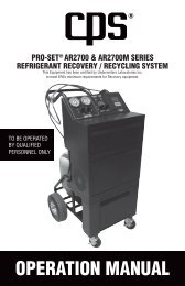
Operation Manual - CPS Products
Operation Manual - CPS Products
Operation Manual - CPS Products

Create successful ePaper yourself
Turn your PDF publications into a flip-book with our unique Google optimized e-Paper software.
DIODE MEASUREMENT<br />
1. Insert the black and red test leads into the COM and VΩHz<br />
input terminals respectively.<br />
2. Set rotary switch at desired Ω position.<br />
3. Push F.FUNC. button to select .<br />
4. The red lead should be connected to the anode and the black<br />
lead to the cathode of the diode.<br />
5. The typical voltage drop should be about 0.6V for silicon<br />
diode or 0.3V for germanium diode.<br />
6. If the diode is reverse biased or there is an open circuit the<br />
reading displayed will be “OL”.<br />
CONTINUITY TESTING<br />
1. Insert the black and red test leads into the COM and VΩHz<br />
input terminals respectively.<br />
2. Set rotary switch at desired Ω position.<br />
3. Push F.FUNC. button to select .<br />
4. If continuity exists (i.e., resistance less than 30Ω) built – in<br />
buzzer will sound.<br />
CAPACITANCE MEASUREMENT<br />
1. Insert the black and red test leads into the COM and VΩHz<br />
input terminals respectively.<br />
2. Turn the rotary switch to ll position.<br />
Connect test leads across the capacitor under measurement<br />
and be sure that the polarity of connection is observed (Note:<br />
The polarity of the red lead connection is positive “+”).<br />
3. Read the measurement directly from the display.<br />
12