Fan Performance Characteristics of Axial Fans - FE-2300 - Aerovent
Fan Performance Characteristics of Axial Fans - FE-2300 - Aerovent
Fan Performance Characteristics of Axial Fans - FE-2300 - Aerovent

Create successful ePaper yourself
Turn your PDF publications into a flip-book with our unique Google optimized e-Paper software.
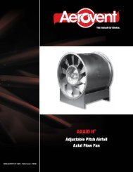
FAN ENGINEERING<br />
®<br />
Information and Recommendations for the Engineer<br />
<strong>FE</strong>-<strong>2300</strong><br />
<strong>Fan</strong> <strong>Performance</strong><br />
<strong>Characteristics</strong> <strong>of</strong> <strong>Axial</strong> <strong>Fan</strong>s<br />
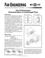
Introduction<br />
There are two general classifications <strong>of</strong> fans: the centrifugal<br />
or radial flow fan (see <strong>FE</strong>-2400) and the propeller<br />
or axial flow fan. In the broadest sense, what sets<br />
them apart is how the air passes through the impeller.<br />
The propeller or axial flow fan propels the air in an<br />
axial direction (Figure 1a) with a swirling tangential<br />
motion created by the rotating impeller blades.<br />
In a centrifugal fan the air enters the impeller axially<br />
and is accelerated by the blades and discharged radially<br />
(Figure 1b).<br />
Figure 1a. <strong>Axial</strong> Flow Figure 1b. Centrifugal Flow<br />
The axial flow fan increases the air velocity through<br />
rotational or tangential force which produces velocity<br />
pressure (VP), kinetic energy, with a very small increase<br />
in static pressure (SP), potential energy.<br />
The centrifugal fan induces airflow by the centrifugal<br />
force generated in a rotating column <strong>of</strong> air producing<br />
potential energy (SP) and also by the rotational (tangential)<br />
velocity imparted to the air as it leaves the tip <strong>of</strong><br />
the blades producing kinetic energy (VP).<br />
<strong>Axial</strong> Flow <strong>Fan</strong>s<br />
<strong>Axial</strong> flow fans come in many variations that all have<br />
one thing in common: they rotate about their axis and<br />
they move a column <strong>of</strong> air parallel to that axis.<br />
The axial fan is commonly found in residential and<br />
commercial applications where emphasis is on moving<br />
large volumes <strong>of</strong> air against relatively low pressures as<br />
economically (low first cost) as possible. The axial fan<br />
is also finding greater acceptance in industrial applications<br />
as alternative equipment to the more expensive<br />
centrifugal (radial flow) fans.<br />
While residential applications are concerned primarily<br />
with creature comfort, commercial and industrial requirements<br />
are expanded to include ventilation for process<br />
as well as worker comfort.<br />
There are many variations <strong>of</strong> axial flow fans, all <strong>of</strong><br />
which have performance characteristics <strong>of</strong> the three<br />
basic types: propeller fans, tubeaxial fans and vaneaxial<br />
fans.<br />
Propeller <strong>Fan</strong>s<br />
Propeller fans can be placed in two categories:<br />
1. Air Circulator or Free <strong>Fan</strong>s — A free fan is one that<br />
rotates in a common unrestricted air space. Examples<br />
<strong>of</strong> free fans include ceiling fans, desk fans, pedestal<br />
fans, and wind fans. With the exception <strong>of</strong> the wind<br />
fans, most <strong>of</strong> these fans are more decorative than<br />
functional. Low tech, low cost designs function to<br />
move and stir the air, but are not necessarily the<br />
most efficient <strong>of</strong> designs.<br />
2. Orifice Panel or Orifice Ring <strong>Fan</strong>s — These are the<br />
fans most associated with applications referred to as<br />
ventilating fans. There are many variations <strong>of</strong> these<br />
arrangements, some with long shaft extensions, direct<br />
connection to a motor, arranged with bearings and<br />
sheaves for belt drive and close coupled belted<br />
arrangements. These fans are designed to transfer air<br />
from one large space to another.<br />
<strong>Axial</strong> panel and ring fan design must respond to many<br />
variables that affect:<br />
• Materials <strong>of</strong> construction <strong>of</strong> the panel or ring<br />
• Materials <strong>of</strong> construction <strong>of</strong> the impeller<br />
• Type <strong>of</strong> impeller blades<br />
• Number <strong>of</strong> impeller blades<br />
• Hub configuration<br />
For example, typically residential<br />
and commercial panel<br />
and ring fans are constructed<br />
using shallow drawn lightweight<br />
metal or plastic orifices.<br />
Impellers for these fans<br />
are also <strong>of</strong> lightweight construction<br />
having from two to<br />
six wide, single thickness,<br />
sometimes overlapping blades<br />
designed for low cost, low<br />
speed and low pressure operation<br />
(Figure 2.)<br />
These fans generally operate<br />
against pressures below<br />
Figure 2. Typical 4-Bladed<br />
Commercial<br />
Impeller<br />
1<br />
⁄2" water gauge, are relatively inefficient and have a<br />
steeply rising power curve (Figure 3) which presents the<br />
danger <strong>of</strong> serious motor overloading in the event the air<br />
passages in the fan system become accidentally<br />
blocked.<br />
©2000 Twin City <strong>Fan</strong> Companies, Ltd.
Figure 3. Characteristic <strong>Performance</strong> <strong>of</strong> a Commercial Panel <strong>Fan</strong> with a Wide Single Thickness 5-Blade Impeller<br />
PERCENT OF NO FLOW STATIC PRESSURE<br />
HORSEPOWER AND EFFICIENCY<br />
100<br />
80<br />
60<br />
40<br />
20<br />
STATIC PRESSURE<br />
TOTAL EFFICIENCY<br />
HORSEPOWER<br />
STATIC EFFICIENCY<br />
0<br />
0 10 20 30 40 50 60 70 80 90 100<br />
PERCENT OF FREE DELIVERY<br />
Like most axial fans, the static pressure curve exhibits<br />
a dip (stall or surge region) where unstable operation<br />
occurs. A fan operating in this region will experience<br />
pulsating behavior and increased noise levels. Extended<br />
operation in this area will result in severe damage to the<br />
structure and the impeller. A fan should be selected to<br />
operate comfortably to the right <strong>of</strong> this stall region. In<br />
the case <strong>of</strong> our example, the fan should be selected to<br />
operate at 70% to 100% <strong>of</strong> free delivery. If this is not<br />
possible, a smaller fan should be chosen for the application.<br />
On the other hand, a typical industrial orifice panel<br />
or ring fan is constructed <strong>of</strong> heavier gauge materials<br />
incorporating a deep drawn venturi (Figure 4). These fans<br />
use stronger, more efficiently designed cast aluminum<br />
airfoil or cambered stamped steel impellers (Figures 5<br />
and 6). While normally designed for pressures up to 1"<br />
<strong>of</strong> water, these fans can be designed to reach 2" to 3"<br />
<strong>of</strong> static pressure.<br />
The designer strives for a fan to have an almost flat<br />
power curve characteristic. Generally speaking, fan<br />
impellers with two to eight narrow-to-medium width<br />
blades have what is called a “flat” power curve. The<br />
power curve rises only slightly from free air to about<br />
mid-range (Figure 7) and then drops slightly with an<br />
upswing near the condition <strong>of</strong> no flow. Increasing the<br />
number <strong>of</strong> blades will usually decrease the free air volume<br />
and increase its ability to work against pressure.<br />
Compare the curves in Figures 3 and 7. Note the<br />
increased operating range (55% to 100%) and higher<br />
Figure 4. Direct Drive Industrial Panel <strong>Fan</strong><br />
With Deep Draw Venturi<br />
Figure 5. Medium Width<br />
Cast Aluminum<br />
Airfoil Impeller<br />
AIRFLOW<br />
Figure 6. Medium Width<br />
Stamped Steel<br />
Impeller<br />
Figure 7. Characteristic <strong>Performance</strong> <strong>of</strong> an Industrial Panel <strong>Fan</strong> with a Medium Width 4-Blade Airfoil Impeller<br />
PERCENT OF NO FLOW STATIC PRESSURE<br />
HORSEPOWER AND EFFICIENCY<br />
100<br />
80<br />
60<br />
40<br />
20<br />
STATIC PRESSURE<br />
HORSEPOWER<br />
TOTAL EFFICIENCY<br />
STATIC EFFICIENCY<br />
0<br />
0 10 20 30 40 50 60 70 80 90 100<br />
PERCENT OF FREE DELIVERY<br />
2 <strong>Fan</strong> Engineering <strong>FE</strong>-<strong>2300</strong>
static pressure capability <strong>of</strong> the industrial panel fan over<br />
the commercial fan. Also note the higher efficiencies<br />
attained by this fan. Now compare the industrial panel<br />
fan performance (Figure 7) against a similar size tubeaxial<br />
fan (Figure 10). We can see that there is a negligible<br />
performance difference between a well designed<br />
industrial panel fan and a tubeaxial fan.<br />
As mentioned previously, specialty panel fans can be<br />
designed to work against pressures <strong>of</strong> 2" to 3" <strong>of</strong> water.<br />
In addition to additional blades these impellers also have<br />
higher “hub-to-tip” ratios (the outside hub diameter<br />
divided by propeller diameter) than typical panel fan<br />
impellers. A low pressure commercial impeller (Figure 2)<br />
might have a hub-to-tip ratio in the range <strong>of</strong> 0.15, while<br />
a well designed industrial impeller (Figures 5 and 6) is<br />
in the range <strong>of</strong> 0.25. A typical higher pressure impeller<br />
(Figure 8) will have a hub-to-tip ratio <strong>of</strong> 0.4 or greater.<br />
Another popular speciality fan utilizes a reversible<br />
propeller, in a double orifice panel. Designed with a<br />
hub-to-tip ratio <strong>of</strong> 0.25, this “S” shaped blade is capable<br />
<strong>of</strong> moving the same airflow at the same horsepower,<br />
in either direction, with the flip <strong>of</strong> a switch. This<br />
propeller exhibits a static pressure curve similar to<br />
Figure 7, combined with a horsepower curve similar to<br />
Figure 3.<br />
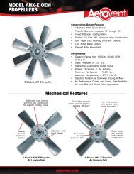
Figure 8. 6-Blade Impeller for Medium Low Pressure<br />
Applications<br />
Figure 9. Direct Drive Tubeaxial <strong>Fan</strong><br />
INLET<br />
BELL<br />
IMPELLER<br />
AIRFLOW<br />
MOTOR WITH<br />
COOLING FAN<br />
OUTLET<br />
CONE<br />
Tubeaxial <strong>Fan</strong>s<br />
The tubeaxial fan (Figure 9) is a propeller fan mounted<br />
in a cylindrical tube or duct and is <strong>of</strong>ten called a duct<br />
fan. <strong>Fan</strong>s <strong>of</strong> this type employ a variety <strong>of</strong> impeller<br />
designs similar to those already described under the<br />
industrial panel fan. The tubeaxial fan can operate in<br />
pressure ranges up to 4" water gauge primarily because<br />
its strong construction allows for higher speeds and<br />
horsepower.<br />
The performance characteristics <strong>of</strong> the tubeaxial fan<br />
are very similar to those previously shown for the industrial<br />
panel fan. The performance curve (Figure 10) is for<br />
a tubeaxial fan using the same impeller that was used<br />
in the industrial panel fan (Figure 7). Generally speaking,<br />
the tubeaxial fan will develop slightly better pressure<br />
characteristics than a similar well designed panel fan.<br />
Tubeaxial fans are designed for use in ducted applications.<br />
Much more versatile than the panel fan by<br />
virtue <strong>of</strong> their construction, they are most adaptable to<br />
ventilation <strong>of</strong> industrial processes. They can be built <strong>of</strong><br />
materials which will stand up under light abrasion, temperatures<br />
up to 600°F, or air heavily contaminated with<br />
corrosive chemicals or explosive vapors. They can be<br />
mounted in parallel for higher airflows or they can be<br />
staged in series to increase their pressure capabilities.<br />
Also, as mentioned under the panel fans, using larger<br />
hub-to-tip ratio impellers increases the tubeaxial fan’s<br />
ability to work against pressure for a given speed or<br />
conversely enables the fan to work against the same<br />
pressure at a lower speed.<br />
Figure 10. Characteristic <strong>Performance</strong> <strong>of</strong> a Tubeaxial <strong>Fan</strong> with a Medium Width 4-Blade Airfoil Impeller<br />
PERCENT OF NO FLOW STATIC PRESSURE<br />
HORSEPOWER AND EFFICIENCY<br />
100<br />
80<br />
60<br />
40<br />
20<br />
STATIC PRESSURE<br />
TOTAL EFFICIENCY<br />
HORSEPOWER<br />
STATIC EFFICIENCY<br />
0<br />
0 10 20 30 40 50 60 70 80 90 100<br />
PERCENT OF FREE DELIVERY<br />
3 <strong>Fan</strong> Engineering <strong>FE</strong>-<strong>2300</strong>
Vaneaxial <strong>Fan</strong>s<br />
The vaneaxial fan (Figure 11) is a variation <strong>of</strong> the duct<br />
fan design which operates in the medium-to-high pressure<br />
ranges. Two to 10 inches water gauge is the<br />
expected pressure range for a single stage fan.<br />
The performance <strong>of</strong> the vaneaxial fan (Figure 12)<br />
shows the pressure curve to rise steeply from free delivery<br />
to a maximum point and then dip sharply into stall.<br />
From the bottom <strong>of</strong> the stall range the pressure rises<br />
again to a higher pressure value at the point <strong>of</strong> no flow.<br />
The increased operating pressure characteristic <strong>of</strong> the<br />
vaneaxial fan is the combined result <strong>of</strong> impeller design<br />
and the guide vanes.<br />
The guide vanes are usually located at the discharge<br />
<strong>of</strong> the impeller. The function <strong>of</strong> the vanes is to recover<br />
the energy <strong>of</strong> rotation and convert this into useful work.<br />
The efficiency <strong>of</strong> the vaneaxial fan rises to a maximum<br />
near the midrange peak pressure point. Its efficiency is<br />
higher than the efficiency <strong>of</strong> other types <strong>of</strong> axial fans,<br />
but the horsepower characteristic is not as flat as that<br />
<strong>of</strong> the industrial panel or tubeaxial fans. The power rises<br />
from free delivery to the mid-range peak pressure, dips<br />
similarly as does the static pressure curve, and then rises<br />
again toward the point <strong>of</strong> no flow.<br />
In designing a system for the vaneaxial fan, it is necessary<br />
to be sure that the point <strong>of</strong> operation is to the<br />
right <strong>of</strong> the dip in the performance curve, but not too<br />
far from the peak pressure point to take advantage <strong>of</strong><br />
maximum efficiency. When operating vaneaxial fans in<br />
parallel, care should be taken to ensure that the flow is<br />
divided equally. Vaneaxial fans work well in series, either<br />
as two stages in a common housing or as two separate<br />
fans installed end to end.<br />
One valued feature <strong>of</strong> the vaneaxial fan is its ability<br />
to allow pitch changes for controlling air volumes, either<br />
through in-flight adjustable or manually adjustable ver-<br />
Figure 11. Belt Driven Vaneaxial <strong>Fan</strong><br />
IMPELLER<br />
GUIDE<br />
VANES<br />
AIRFLOW<br />
BEARING<br />
CASING<br />
BELT<br />
TUBE<br />
sions. The adjustable pitch versions are limited to clean<br />
air applications; however, fans with cast solid impellers<br />
can be designed to handle high temperatures and<br />
chemical contaminated air. Vaneaxial fans are not recommended<br />
for applications containing abrasives, dust,<br />
stringy materials or overspray since buildup on the guide<br />
vanes will decrease fan performance.<br />
Conclusion<br />
Propeller fans have many advantages over other forms<br />
<strong>of</strong> air moving devices and the recognition <strong>of</strong> these has<br />
brought about rapid progress in their development and<br />
use. Among the main advantages <strong>of</strong> propeller fans are<br />
their high capacity-to-weight ratio, the inline flow design<br />
making installation in ducts simple, and the broad range<br />
<strong>of</strong> high efficiency performance.<br />
Figure 12. Characteristic <strong>Performance</strong> <strong>of</strong> a Vaneaxial <strong>Fan</strong> with a Medium Width 7-Blade Airfoil Impeller<br />
HORSEPOWER<br />
PERCENT OF NO FLOW STATIC PRESSURE<br />
HORSEPOWER AND EFFICIENCY<br />
100<br />
80<br />
60<br />
40<br />
20<br />
TOTAL EFFICIENCY<br />
STATIC EFFICIENCY<br />
STATIC PRESSURE<br />
0<br />
0 10 20 30 40 50 60 70 80 90 100<br />
PERCENT OF FREE DELIVERY<br />
®<br />
<strong>Aerovent</strong> | www.aerovent.com<br />
5959 Trenton Lane N | Minneapolis, MN 55442 | Phone: 763-551-7500 | Fax: 763-551-7501