G2, G4 & G5 Gauge Manual - Innovate Motorsports
G2, G4 & G5 Gauge Manual - Innovate Motorsports
G2, G4 & G5 Gauge Manual - Innovate Motorsports

Create successful ePaper yourself
Turn your PDF publications into a flip-book with our unique Google optimized e-Paper software.
<strong>G2</strong>, <strong>G4</strong> & <strong>G5</strong> <strong>Gauge</strong> <strong>Manual</strong><br />
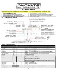
Please follow the instructions that came with your wideband (LC-1, LC-2, or LM-2) prior to installing the gauge.<br />
<br />
<br />
<br />
<br />
ALWAYS WEAR SAFETY GLASSES.<br />
Install gauge only when engine is cool and ignition is off.<br />
Make sure all necessary tools, materials, and parts are on hand.<br />
Disconnect negative (-) battery cable before installing gauge.<br />
<br />
<br />
2-1/16" gauge mounts in a 2-1/16" diameter hole.<br />
Make sure mounting location does not impair visibility or interfere with<br />
driving. Also check behind the mounting location for any wiring or<br />
components before drilling.<br />
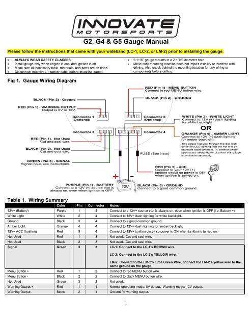
Fig 1. <strong>Gauge</strong> Wiring Diagram<br />
Table 1. Wiring Summary<br />
Color Pin Connector Notes<br />
12V+ (Battery) Purple 1 4 Connect to a 12V+ source that is always on, even when ignition is OFF (i.e. Battery +)<br />
White Light White 2 4 Connect to 12V+ dash lighting for white backlight.<br />
Ground Black 3 4 Connect to a good common ground.<br />
Amber Light Orange 4 4 Connect to 12V+ dash lighting for amber backlight.<br />
12V+ ACC (Ignition) Red 5 4 Connect to 12V+ ignition circuit so power is ON when ignition is turned on.<br />
Not Used Red 1 3 Not used. Cut and seal wire.<br />
Not Used Black 2 3 Not used. Cut and seal wire.<br />
Signal Green 3 3 LC-1: Connect to the LC-1’s BROWN wire.<br />
LC-2: Connect to the LC-2’s YELLOW wire.<br />
Menu Button + Red 1 2 Connect to red MENU button wire.<br />
Menu Button - Black 2 2 Connect to black MENU button wire.<br />
Not Used Green 3 2 Not used.<br />
LM-2: Connect to the LM-2’s Lime Green Wire, connect the LM-2’s yellow wire to the<br />
same ground as the gauge.<br />
Warning Output + Red 1 1 Normal operating mode: 0V output. Warning mode: 12V output.<br />
Warning Output - Black 2 1 Ground for warning output.<br />
1
Wiring<br />
Use 20 AWG stranded or heavier wire for installation. Route wires away from<br />
any moving parts and hot engine components. Secure wires firmly along their<br />
route. Cut and seal all unused wire connections.<br />
Signal Input<br />
The gauge is setup to work with the <strong>Innovate</strong> <strong>Motorsports</strong>’ factory wideband<br />
output of 0v = 7.35 A/F and 5v = 22.39 A/F.<br />
Note: As a safety precaution, the RED (Pin 5) and PURPLE (Pin 1) 12V+<br />
connections should be fused. We recommend using a 1 Amp, 3 AG fast-acting<br />
type cartridge fuse.<br />
MENU Button Installation (Optional)<br />
Installation of the remote MENU button is only necessary if you want to use the<br />
RECALL and WARNING features of the gauge. Installation of the MENU<br />
button is NOT required if you do not wish to use the RECALL or WARNING<br />
features.<br />
Mount the included MENU button in a location that is convenient. Connect the<br />
red wire from the button to Connector 2, Pin 1 (Red) and the black wire on the<br />
button to Connector 2, Pin 2 (Black). See Fig 1.<br />
Programming Full Dial Low Warning (WARN LO)<br />
This gauge can be configured to show a full dial low warning (flashing amber<br />
backlight) when the gauge goes BELOW a specific value (i.e. AFR goes below<br />
10).<br />
1. To access WARN LO programming mode, press and hold the<br />
MENU button until the pointer moves to 25% scale (approx 1<br />
second). Release the MENU button after the pointer has reached<br />
25% scale.<br />
2. After releasing the MENU button the pointer will move to the current<br />
low warning set point. Factory default is 0% scale (WARN LO<br />
deactivated).<br />
3. To change the set point, press the MENU button repeatedly to move<br />
the pointer by 2% increments. Once the pointer reaches 100%<br />
scale, pressing the MENU button will decrease the pointer position<br />
by 2% increments.<br />
4. Once the pointer indicates your desired low warning set point leave<br />
the MENU button untouched for 5 seconds. The low warning set<br />
point will be saved and the gauge will return to normal operating<br />
mode.<br />
To turn the low warning OFF, repeat steps 1-4 above and change the low<br />
warning set point to 0% or 2% scale. Setting the low warning set point to 0%<br />
or 2% deactivates the low warning feature.<br />
Viewing and Clearing Peak Value (RECALL)<br />
1. To view the peak value, press the MENU button one time.<br />
2. To exit RECALL mode press the MENU button one time.<br />
3. To clear the stored peak value press and hold the MENU button for<br />
3 seconds while in RECALL mode.<br />
External Warning Output (Optional)<br />
When warning mode is active the gauge outputs a 12V+ DC signal (500mA)<br />
on Pin 1 of Connector #1 (See Fig 1). This output is 0V when warning mode<br />
is not active. This output can be used to activate an external warning light or<br />
activate a switch.<br />
Do not install Connector 1 if external warning output is not required.<br />
Lens Protective Film<br />
The gauge comes with a soft protective plastic film on the lens. Carefully<br />
remove the protective film when gauge installation is complete.<br />
Lens Cleaning<br />
The gauge lens is made of acrylic plastic. Do not use any chemicals or<br />
abrasives on the lens. To prevent scratching, caution must be used when<br />
cleaning. To clean, wipe lightly with a damp soft cloth.<br />
Programming Full Dial High Warning (WARN HI)<br />
This gauge can be configured to show a full dial high warning (flashing amber<br />
backlight) when the gauge goes ABOVE a specific value (i.e. AFR goes above<br />
17).<br />
1. To access WARN HI programming mode, press and hold the remote<br />
button until the pointer moves to 75% scale (approx 3 seconds).<br />
Note: the pointer will stop at 25% scale for approx 1 second (for<br />
WARN LO programming mode), continue holding the button until the<br />
pointer has reached 75% scale. Release the button after pointer<br />
has reached 75% scale.<br />
2. After releasing the button the pointer will move to the current high<br />
warning set point. Factory default is 100% scale (WARN HI<br />
deactivated).<br />
3. To change the set point, press the MENU button repeatedly to move<br />
the pointer by 2% increments. Once the pointer reaches 0% scale,<br />
pressing the MENU button will increase the pointer position by 2%<br />
increments.<br />
4. Once the pointer indicates your desired high warning set point leave<br />
the MENU button untouched for 5 seconds. The high warning set<br />
point will be saved and the gauge will return to normal operating<br />
mode.<br />
To turn the high warning OFF, repeat steps 1-4 above and change the high<br />
warning set point to 98% or 100% scale. Setting the high warning set point to<br />
98% or 100% deactivates the high warning feature.<br />
Full Dial Warning (ON/OFF)<br />
If desired, the full dial warning can be turned OFF so that only the External<br />
Warning Output activates when a high or low warning condition exists. To<br />
turn Full Dial Warning OFF (or ON):<br />
1. Press and hold the MENU button until the pointer moves to 100%<br />
scale (approx 4 seconds). Note: the pointer will stop at 25% scale<br />
for approx 1 second, then 75% for approx. 1 second. Do not release<br />
the MENU button until the pointer has reached 100% scale.<br />
Release the button after the pointer reaches 100% scale.<br />
2. After releasing the button the gauge backlighting will indicate<br />
whether Full Dial Warning is currently ON or OFF. <strong>Gauge</strong><br />
backlighting will flash to indicate Full Dial Warning Mode is ON.<br />
<strong>Gauge</strong> will remain unlit to indicate Full Dial Warning Mode is OFF.<br />
3. Press the remote button to switch between Full Dial Warning ON<br />
(flashing backlight) and OFF (no backlighting).<br />
4. To save your changes, leave the MENU button untouched for 5<br />
seconds. Full Dial Warning Mode (ON or OFF) will be saved and<br />
the gauge will return to normal operating mode.<br />
Doc# 11-0127 (Rev. C)<br />
2