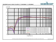
SPECIFICATIONS - AkustyK
SPECIFICATIONS - AkustyK
SPECIFICATIONS - AkustyK

Create successful ePaper yourself
Turn your PDF publications into a flip-book with our unique Google optimized e-Paper software.
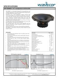
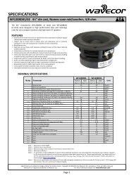
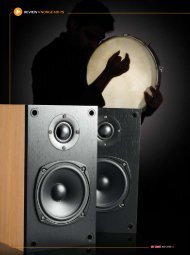
<strong>SPECIFICATIONS</strong><br />
WF182BD03/04 7” die cast, paper cone mid/woofers, 4/8 ohm<br />
The 7” transducers WF182BD03 (4 ohm) and WF182BD04 (8 ohm)<br />
were designed as high performance bass and midrange units for<br />
monitors and high-end hi-fi speakers. They offer outstanding deep<br />
bass performance and dynamic and detailed midrange.<br />
FEATURES<br />
• Balanced Drive motor structure for optimal drive force symmetry resulting in<br />
largely reduced even order harmonic distortion<br />
• Copper cap on center pole to reduce voice coil inductance and to minimize<br />
variations in voice coil inductance as a function of voice coil position<br />
• Black coated semi-air-dried paper cone<br />
• Rigid die cast alu chassis with extensive venting for lower air flow speed reducing<br />
audible distortion<br />
• Vented voice coil former for reduced distortion and compression<br />
• Vented center pole with dual flares for reduced noise level at large cone<br />
excursions<br />
• Heavy-duty black fiber glass voice coil former to reduce mechanical losses resulting<br />
in better dynamic performance and low-level details<br />
• Large motor with 1½” voice coil diameter for better control and power handling<br />
• Built-in alu field-stabilizing ring for reduced distortion at high levels<br />
• Low-loss suspension (high Qm) for better reproduction of details and dynamics<br />
• Black motor parts for better heat transfer to the surrounding air<br />
• Conex spider for better durability under extreme conditions<br />
• Gold plated terminals to ensure long-term trouble free connection<br />
NOMINAL <strong>SPECIFICATIONS</strong><br />
WF182BD03 WF182BD04<br />
Notes Parameter<br />
Before<br />
burn-in<br />
After<br />
burn-in<br />
Before<br />
burn-in<br />
After<br />
burn-in<br />
Unit<br />
Nominal size 7 7 [inch.]<br />
Nominal impedance 4 8 [ohm]<br />
Recommended max. upper frequency limit 2.5 2.5 [kHz]<br />
1 Sensitivity, 2.83V/1m (average SPL in range 200 - 1,000 Hz) 91 88 [dB]<br />
2 Power handling, short term, IEC 268-5, no additional filtering [W]<br />
2 Power handling, long term, IEC 268-5, no additional filtering [W]<br />
2 Power handling, continuous, IEC 268-5, no additional filtering 80 80 [W]<br />
Effective radiating area, Sd 131 131 [cm²]<br />
3, 6 Resonance frequency (free air, no baffle), Fs 39 33.8 40 33.4 [Hz]<br />
Moving mass, incl. air (free air, no baffle), Mms 16.7 16.1 [g]<br />
3 Force factor, Bxl 6.75 8.5 [N/A]<br />
3, 6 Suspension compliance, Cms 1.0 1.33 1.0 1.33 [mm/N]<br />
3, 6 Equivalent air volume, Vas 24.4 32.4 24.4 32.4 [lit.]<br />
3, 6 Mechanical resistance, Rms 0.37 0.43 0.37 0.43 [Ns/m]<br />
3, 6 Mechanical Q, Qms 11 8.2 10.9 8.1 [-]<br />
3, 6 Electrical Q, Qes 0.30 0.26 0.35 0.30 [-]<br />
3, 6 Total Q, Qts 0.29 0.25 0.34 0.29 [-]<br />
4 Voice coil resistance, RDC 3.3 6.3 [ohm]<br />
5 Voice coil inductance, Le (measured at 10 kHz) 0.088 0.14 [mH]<br />
Voice coil inside diameter 39 39 [mm]<br />
Voice coil winding height 16 16 [mm]<br />
Air gap height 5 5 [mm]<br />
Magnet weight 885 885 [g]<br />
Total unit net weight excl. packaging 2.3 2.3 [kg]<br />
3, 5 Krm 33 54 [mohm]<br />
3, 5 Erm 0.42 0.40 [-]<br />
3, 5 Kxm 157 347 [mH]<br />
3, 5 Exm 0.19 0.14 [-]<br />
Note 1<br />
Note 2<br />
Note 3<br />
Note 4<br />
Note 5<br />
Measured in infinite baffle.<br />
Tested in free air (no cabinet).<br />
Measured using a semi-constant current source, nominal level 2 mA.<br />
Measured at 20 deg. C<br />
It is generally a rough simplification to assume that loudspeaker transducer voice coils exhibit the characteristics of an inductor. Instead it<br />
is a far more accurate approach to use the more advanced model often referred to as the “Wright empirical model”, also used in LEAP-4 as<br />
the TSL model (www.linearx.com), involving parameters Krm, Erm, Kxm, and Exm. This more accurate transducer model is described in a<br />
technical paper here at our web site.<br />
Note 6 After burn-in specifications are measured 12 hours after exiting the transducer by a 20 Hz sine wave for 2 hours at level 10/14.1 VRMS (4/8<br />
ohm version). The unit is not burned in before shipping.<br />
Specifications are subject to change without any further notice. Copyright © 2010 by Wavecor Ltd., Guangzhou, China. All rights reserved.<br />
Wavecor® is a registered trademark of Wavecor Ltd.<br />
For more information please visit www.Wavecor.com<br />
Page 1
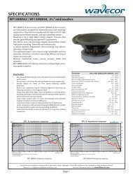
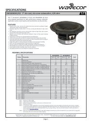
<strong>SPECIFICATIONS</strong><br />
WF182BD03/04 7” die cast, paper cone mid/woofers, 4/8 ohm<br />
dBSPL<br />
110<br />
105<br />
100<br />
95<br />
90<br />
SPL & impedance response, WF182BD03<br />
on axis<br />
15 deg. off axis<br />
30 deg. off axis<br />
45 deg. off axis<br />
60 deg. off axis<br />
Impedance<br />
Ohm<br />
300<br />
200<br />
100<br />
50<br />
85<br />
80<br />
75<br />
20<br />
10<br />
70<br />
65<br />
5<br />
60<br />
20<br />
50<br />
100<br />
200<br />
500<br />
1k<br />
2k<br />
5k<br />
2<br />
10k 20k<br />
Frequency, Hz<br />
Measuring conditions, SPL<br />
Driver mounting: Flush in infinite<br />
baffle, back side open (no cabinet)<br />
Microphone distance: 1.0 m<br />
Input level: 2.83 V RMS<br />
Smoothing: 1/6 oct.<br />
Measuring conditions, impedance<br />
Driver mounting: Free air, no baffle,<br />
back side open (no cabinet)<br />
Input signal: Semi-current-drive,<br />
nominal current 2 mA<br />
Smoothing: None<br />
dBSPL<br />
110<br />
105<br />
100<br />
95<br />
90<br />
SPL & impedance response, WF182BD04<br />
on axis<br />
15 deg. off axis<br />
30 deg. off axis<br />
45 deg. off axis<br />
60 deg. off axis<br />
Impedance<br />
Ohm<br />
300<br />
200<br />
100<br />
50<br />
85<br />
80<br />
75<br />
20<br />
10<br />
70<br />
65<br />
5<br />
60<br />
20<br />
50<br />
100<br />
200<br />
500<br />
1k<br />
2k<br />
5k<br />
2<br />
10k 20k<br />
Frequency, Hz<br />
Specifications are subject to change without any further notice. Copyright © 2010 by Wavecor Ltd., Guangzhou, China. All rights reserved.<br />
Wavecor® is a registered trademark of Wavecor Ltd.<br />
For more information please visit www.Wavecor.com<br />
Page 2
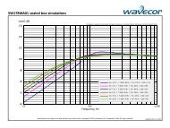
<strong>SPECIFICATIONS</strong><br />
WF182BD03/04 7” die cast, paper cone mid/woofers, 4/8 ohm<br />
OUTLINE DRAWING<br />
(nominal dimensions, mm)<br />
5<br />
max. 84<br />
6<br />
7.5 3<br />
120<br />
max. 153<br />
Foam gasket<br />
169.5<br />
182<br />
CONNECTIONS<br />
Red mark for positive terminal<br />
6.5<br />
7.1<br />
4.8 2.8<br />
Thickness, both terminals: 0.5 mm<br />
Terminal plating: Gold<br />
PACKAGING AND ORDERING INFORMATION<br />
Part no. WF182BD03-01 4 ohm version, individual packaging (one piece per box)<br />
Part no. WF182BD03-02 4 ohm version, bulk packaging<br />
Part no. WF182BD04-01 8 ohm version, individual packaging (one piece per box)<br />
Part no. WF182BD04-02 8 ohm version, bulk packaging<br />
Latest update: September 8, 2010<br />
Specifications are subject to change without any further notice. Copyright © 2010 by Wavecor Ltd., Guangzhou, China. All rights reserved.<br />
Wavecor® is a registered trademark of Wavecor Ltd.<br />
For more information please visit www.Wavecor.com<br />
Page 3