Proportional Control Valves - Nachi Hidrolik
Proportional Control Valves - Nachi Hidrolik
Proportional Control Valves - Nachi Hidrolik

You also want an ePaper? Increase the reach of your titles
YUMPU automatically turns print PDFs into web optimized ePapers that Google loves.
<strong>Proportional</strong> <strong>Control</strong> <strong>Valves</strong><br />
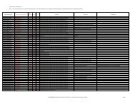
Photo Type Series Description Main Specifications<br />
Pressure<br />
<strong>Control</strong><br />
EPR<br />
Electro-Hydraulic<br />
<strong>Proportional</strong> Pilot Relief<br />
Valve<br />
0.3gpm, 5000psi<br />
Pressure<br />
<strong>Control</strong><br />
ER<br />
Electro-Hydraulic<br />
<strong>Proportional</strong> Relief<br />
Valve<br />
39.7 - 84.6gpm, 5000psi<br />
Pressure<br />
<strong>Control</strong><br />
EGB<br />
Electro-Hydraulic<br />
<strong>Proportional</strong> Reducing<br />
and Relief Valve<br />
13.2 - 26.4gpm, 3000psi<br />
Flow<br />
<strong>Control</strong><br />
ES<br />
Electro-Hydraulic<br />
<strong>Proportional</strong> Flow<br />
<strong>Control</strong> Valve<br />
0.08 - 132.1gpm, 3000psi<br />
Flow &<br />
Directional<br />
<strong>Control</strong><br />
ESD<br />
Electro-Hydraulic<br />
<strong>Proportional</strong> Directional<br />
and Flow <strong>Control</strong> Valve<br />
6.6 - 66.1gpm, 3571psi<br />
NA<br />
Pressure<br />
<strong>Control</strong><br />
EOG<br />
Modular Type Electro-<br />
Hydraulic <strong>Proportional</strong><br />
Reducing Valve<br />
7.9gpm, 3571psi<br />
Flow<br />
<strong>Control</strong><br />
EOF<br />
Modular Type Electro-<br />
Hydraulic <strong>Proportional</strong><br />
Reducing Valve<br />
0.08 - 6.6gpm, 3000psi<br />
Amplifier<br />
EDA/EDC<br />
Small Type Amplifier<br />
Series for Electro-<br />
Hydraulic <strong>Proportional</strong><br />
Valve<br />
NA
EPR Series<br />
Electro-hydraulic <strong>Proportional</strong> Pilot Relief Valve (EPR)<br />
Features<br />
This is a direct acting type relief valve<br />
based on a balance between the<br />
attraction force of a DC solenoid and<br />
a hydraulic force.<br />
This valve can be utilized in a small<br />
capacity hydraulic system or connected<br />
to the vent-port of a balance piston<br />
type pressure control valve to<br />
perform continuous control of the<br />
pressure in proportion to the input<br />
current.<br />
Specifications<br />
Understanding Model Numbers<br />
EPR G 01 2 ( S) 12<br />
EPR-G01-*-****-*12<br />
B: 3 ~ 25 (43 ~ 357)<br />
1: 7 ~ 70 (100 ~ 1000)<br />
2: 10 ~ 140 (143 ~ 2000)<br />
3: 15 ~ 210 (214 ~ 3000)<br />
4: 15 ~ 280 (214 ~ 4000)<br />
5: 20 ~ 350 (286 ~ 5000)<br />
Design Code<br />
Mounting bolt No code: Metric thread<br />
E: Unified thread<br />
Moving core shockless type<br />
Symbol for tank port orifice<br />
(Example) 09: 0.9 (0.04 Dia), See table. 1<br />
Symbol for pressure port orifice<br />
(Example) 12: 1.2 (0.05 Dia), See table. 1<br />
Pressure adjusting range. B, 1, 2, 3, 4, 5<br />
Valve Size: 01<br />
Mounting method G: Gasket Mounting<br />
Electro-hydraulic <strong>Proportional</strong> Pilot Relief Valve<br />
Number of Pressure port and Tank port orifice<br />
Number<br />
Note) Standard size is as below.<br />
Orifice number<br />
5 type 1111S<br />
φ<br />
φ<br />
¡Handling<br />
zAir Bleeding<br />
Loosen the air vent to bleed the air<br />
and fill the solenoid with oil at the<br />
start of operation to obtain good<br />
pressure control.<br />
The position of the air vent can be<br />
changed by turning the cover.<br />
xInstallation Method<br />
The minimum pressure will<br />
become approximately 2kgf/cm 2<br />
(29 psi) higher when this valve is<br />
attached on a vertical plane.<br />
cManual Pressure Adjusting Screw<br />
When there is no input current supplied<br />
to the valve as in the case of<br />
initial adjustment or due to an electrical<br />
fault, the valve pressure can<br />
be controlled temporarily by turning<br />
the manual adjusting screw. In normal<br />
operation, this manual adjusting<br />
screw must be retracted completely<br />
and fixed with the lock nut.<br />
vMinimum Relief Flow<br />
Since the setting pressure may<br />
become unstable in case of low<br />
flow rate, use this valve at a flow<br />
rate of 0.3r/min (0.08 gpm) or<br />
more.<br />
bLoad Capacity<br />
When the circuit pressure is to be<br />
controlled directly by this valve, the<br />
load capacity must be 40cc (2.4<br />
in 3 ) or more.<br />
nMounting Bolts<br />
M5 x 45r (E: 10-24 UNC-3A x<br />
1 3 /4"), Grade 12.9 tightening torque<br />
= 50~70 kgf·cm (4~5 lbs·ft)<br />
mSubplate<br />
When a subplate is required, specify<br />
the following type in the purchase<br />
order.<br />
MSA-01Y-*10 (refer to dimensions<br />
in the figure below.)<br />
,Oil Temperature<br />
-20°C~70°C (-4°F~158°F)<br />
.Oil Viscosity<br />
12~400 cSt<br />
15~60 cSt is recommended.<br />
⁄0Gasket Dimension<br />
ISO 4401-03-02-0-94<br />
PV-3
Installation Dimensions<br />
mm (inch)<br />
Performance Curves<br />
Input Current-Pressure Characteristics<br />
Oil viscosity = 32 cSt<br />
(5714) 400<br />
(5000) 350<br />
EPR-G01-5<br />
Cross Section Drawing<br />
EPR-G01-*-****-*12<br />
List of Seals<br />
PV-4
ER Series<br />
Electro-hydraulic <strong>Proportional</strong> Relief Valve (ER)<br />
Features<br />
This valve is a combination of the<br />
electro-hydraulic proportional pilot<br />
relief valve (EPR Series) and a balance<br />
piston type relief valve and is<br />
used to perform pressure control in<br />
proportion to the input current.<br />
Since the control pressure is affected<br />
very little by changes of flow rate or<br />
oil temperature, even complicated<br />
pressure (power) control can be performed<br />
by an open loop system.<br />
Specifications<br />
ER-G03-*-*21<br />
ER-G06-*-*21<br />
Understanding Model Numbers<br />
ER G 03 3 21<br />
Design number.<br />
Mounting bolt No code: Metric thread<br />
E: Unified thread<br />
Pressure adjusting range. 1, 2, 3, 4, 5<br />
Valve size. 03, 06<br />
Mounting. G: Gasket mounting<br />
Electro hydraulic <strong>Proportional</strong> Relief Valve<br />
Installation Dimensions<br />
mm (inch)<br />
¡Handling<br />
zAir Bleeding<br />
Loosen the air vent to bleed the air<br />
thoroughly and fill oil in the solenoid<br />
at the start of operation to<br />
obtain good pressure control.<br />
xManual Pressure Adjusting Screw<br />
When there is no input current supplied<br />
to the valve as in the case of<br />
initial adjustment or due to an electrical<br />
fault, the valve pressure can<br />
be controlled temporarily by turning<br />
the manual adjusting screw. In normal<br />
operation, this manual adjust<br />
screw must be retracted completely<br />
and fixed with the locknut.<br />
cTank Port Back-Pressure<br />
Use the valve with a tank port<br />
back-pressure which is as low as<br />
possible. 2 kgf/cm 2 (29 psi) or less<br />
is recommended.<br />
vSetting Pressure of Safety valve<br />
The safety valve is set for a pressure<br />
that is 15~20 kgf/cm 2<br />
(214~286 psi) above the maximum<br />
adjusting pressure. Adjust this<br />
safety valve setting in accordance<br />
with the pressure to be actually<br />
used.<br />
bMounting Bolts<br />
Grade = 12.9<br />
nOil Temperature<br />
-20°C~70°C (-4°F~158°F)<br />
mOil Viscosity<br />
12~400 cSt<br />
15~60 cSt is recommended.<br />
,Gasket Dimension<br />
G03 = ISO 6264-AR-06-2-A<br />
G06 = ISO 6264-AS-08-2-A<br />
PV-5
Subplate<br />
MRI-03*-E10<br />
MRI-06*-E10<br />
Performance Curves<br />
Input Current-Pressure Characteristics<br />
ER-G06-*-*21<br />
Oil viscosity = 32 cSt<br />
Pressure Override Characteristics<br />
ER-G06-*-*21<br />
Cross Section Drawing<br />
ER-G**-*-*21<br />
Combination with EPR Valve<br />
ER-G03-B-21<br />
ER-G06-1-21<br />
EPR-G01-B-0011S-12<br />
1-0011S-12<br />
2-1313S-12<br />
3-1313S-12<br />
4-1212S-12<br />
5-1212S-12<br />
EPR-G01-1-0011S-12<br />
2-1313S-12<br />
3-1313S-12<br />
4-1212S-12<br />
5-1212S-12<br />
List of Seals<br />
ER-G03-*-*20<br />
ER-G06-*-*20<br />
PV-6
EGB Series<br />
Electro-hydraulic <strong>Proportional</strong> Reducing and Relief Valve<br />
Features<br />
This is a combination of the electrohydraulic<br />
proportional pilot relief valve<br />
(EPR Series) and a reducing valve<br />
with a relief and is used to perform<br />
pressure reducing control of the pressure<br />
in a hydraulic system in proportion<br />
to the input current. Since a relief<br />
function is provided, the outlet side<br />
pressure can be maintained practically<br />
constant even when a reaction<br />
force acts on the valve outlet side.<br />
Owing to this feature, the response<br />
performance are very good.<br />
Specifications<br />
EGB-G03<br />
*-*11<br />
Understanding Model Numbers<br />
EGB G 03 2 11<br />
Design number.<br />
Mounting bolt No code: Metric thread<br />
E: Unified thread<br />
Pressure adjusting range. 1, 2, 3<br />
Valve size. 03, 06<br />
Mounting method G: Gasket mounting<br />
Electro-hydraulic <strong>Proportional</strong> Reducing and Relief Valve<br />
Installation Dimensions<br />
EGB-G03-*-*11<br />
mm (inch)<br />
EGB-G06-*-*11<br />
EGB-G06<br />
*-*11<br />
¡Handling<br />
zAir Bleeding<br />
Loosen the air vent to bleed the air<br />
throughly and fill oil in the solenoid at<br />
the start of operation to obtain good<br />
pressure control.<br />
xDR Port Piping<br />
Please take care in piping so that the<br />
DR port (in case of G06 size T port) is<br />
always filled up with oil.<br />
c Manual Pressure Adjusting Screw<br />
When there is no input current supplied<br />
to the valve as in the case of initial<br />
adjustment or due to an electrical fault,<br />
the valve pressure can be controlled<br />
temporarily by turning the manual<br />
adjusting screw. In normal operation,<br />
this manual adjusting screw must be<br />
retracted completely and fixed with the<br />
locknut.<br />
v Load Capacity<br />
Use this valve with a load capacity<br />
(Valve outlet side capacity) or 5r (305<br />
in 3 ) or more.<br />
b Mounting Bolts<br />
n Oil temperature<br />
-20~70°C (-4°F~158°F)<br />
m Oil viscosity<br />
12~400 cSt<br />
15~60 cSt is recommended.<br />
Installation Gasket Dimensions<br />
EGB-G03-*-*11<br />
Installation Gasket Dimensions<br />
EGB-G06-*-*11<br />
PV-7
Performance Curves<br />
Oil viscosity = 32 cSt<br />
Input current-Pressure Characteristics<br />
EGB-G03<br />
EGB-G06<br />
Cross Section Drawing<br />
EGB-G**-*-*11<br />
Combination with EPR Valve<br />
List of Seals<br />
ER-G03-*-*11<br />
ER-G06-*-*11<br />
PV-8
EOG Series<br />
Modular Type Electro-hydraulic <strong>Proportional</strong> Reducing Valve (EOG)<br />
Features<br />
This valve is the expansion of modular<br />
valve idea into electro-hydraulic<br />
proportional reducing valve, and it is<br />
used to perform pressure reducing<br />
control of the pressure in a hydraulic<br />
EOG<br />
Specifications<br />
Understanding Model Numbers<br />
Installation Dimensions<br />
EOG-G01-P*<br />
G01 P1 11<br />
Design Number<br />
Mounting bolt<br />
No Code: Metric<br />
Pressure adjusting range: B, 1, 2<br />
<strong>Control</strong> port P<br />
Valve size 01<br />
Mounting method G: Gasket mounting<br />
Modular Type Electro <strong>Proportional</strong> Reducing Valve<br />
system in proportion to the input current.<br />
This valve is most suited for small<br />
hydraulic systems, such as continuous<br />
proportional control of the lathe's<br />
E: Unified thread<br />
mm (inch)<br />
EOG-G01-P*-*11<br />
work chuck pressure of machine<br />
tools. Since a relief function is provided,<br />
the response performance to the<br />
pressure is very good.<br />
¡Handling<br />
zAir Bleeding<br />
Loosen the air vent to bleed the air<br />
throughly and fill oil in the solenoid<br />
at the start of operation to obtain<br />
good pressure control.<br />
xManual Pressure Adjusting Screw<br />
When there is no input current supplied<br />
to the valve as in the case of<br />
initial adjustment or due to an electrical<br />
fault, the valve pressure can<br />
be controlled temporarily by turning<br />
the manual adjusting screw. In normal<br />
operation, this manual adjusting<br />
screw must be retracted completely<br />
and fixed with the clocknut.<br />
cT-Port Back Pressure<br />
Since this is the internal drain system,<br />
keep the valve T-port back<br />
pressure less than 25 kgf/cm 2 (357<br />
psi).<br />
vLoad capacity<br />
Please make load capacity (outside<br />
piping capacity) more than<br />
0.5r (0.13 gallon).<br />
bOil Temperature<br />
-20~70°C (-4°F~158°F)<br />
nOil Viscosity<br />
12~400 cSt<br />
15~60 cSt is recommended.<br />
mGasket Dimension<br />
ISO 4401-03-02-0-94<br />
PV-22
Performance Curves<br />
Oil viscosity 32 cSt<br />
Input Current-Pressure Characteristics<br />
EOG-G01<br />
Flow Rate-Pressure Characteristics<br />
EOG-G01-PB EOG-G01-P1 EOG-G01-P2<br />
Oil Temperature Characteristics<br />
EOG-G01-PB EOG-G01-P1 EOG-G01-P2<br />
Cross Section Drawings<br />
EOG-G01-P*-*11<br />
PV-23
ES Series<br />
Electro-hydraulic <strong>Proportional</strong> Flow <strong>Control</strong> Valve (ES)<br />
Features<br />
The actuator speed can be controlled<br />
optionally according to the input current.<br />
Since the setting flow rate is affected<br />
very little by changes of the pressure<br />
or oil temperature, high accuracy<br />
speed control is possible. This valve<br />
is most suited for acceleration and<br />
deceleration control of the actuator<br />
and remote control.<br />
Specifications<br />
(C)ES-G02<br />
-10/30-(F)-*12<br />
ES-G03<br />
-60/125-(F)-*12<br />
Understanding Model Numbers<br />
(C)ES G 02 30 (F) 12<br />
(C)ES-G06<br />
-250-*11<br />
Design number 11: 06, 10 size<br />
12: 02, 03 size<br />
Mounting bolt<br />
No code: Metric thread<br />
E: Unified thread<br />
Auxiliary code F: with jumping preventable (Option)<br />
(Note): Only for valve size 02, 03, 10<br />
Max. metered flow<br />
Valve Size: 02, 03, 06, 10<br />
Mounting method G: Gasket mounting<br />
ES-G10<br />
-500-(F)-*11<br />
¡Handling<br />
zAir Bleeding<br />
Loosen the air vent and bleed the<br />
air thoroughly and fill oil in the<br />
solenoid at the start of operation to<br />
obtain stable flow control.<br />
The position of the air vent be<br />
changed by turning the cover.<br />
xManual Flow Adjusting Screw<br />
When there is no input current supplies<br />
to the valve as in the case of<br />
initial adjustment or due to an electrical<br />
fault, the flow can be adjusted<br />
by turning the manual adjusting<br />
screw. In normal operation, this<br />
adjusting screw must be retracted<br />
completely and fixed by the locknut.<br />
cDrain Port<br />
Connect the drain port directly to<br />
the oil tank so that the back-pressure<br />
will be 2 kgf/cm 2 (29 psi) or<br />
less.<br />
vMounting Bolts<br />
CES: Electro-hydraulic <strong>Proportional</strong> Flow <strong>Control</strong> Valve with check valve. Only 02. and 06.<br />
ES: Electro-hydraulic <strong>Proportional</strong> Flow <strong>Control</strong> Valve<br />
Installation Dimensions<br />
mm (inch)<br />
bIf the distance between the flow<br />
control valve and the actuator is<br />
long (Piping volume is large.). resonance<br />
of the load system and the<br />
control valve may occur in some<br />
cases.<br />
nSubplate<br />
Refer to page 8 for details.<br />
mOil Temperature<br />
-20~70°C (-4°F~158°F)<br />
,Oil Viscosity<br />
12~400 cSt<br />
15~60 cSt is recommended.<br />
.Gasket Dimension<br />
(C)ES-G02 = ISO 6263-06-05-97<br />
ES-G03 = ISO 6263-07-09-97<br />
(C)ES-G06 = ISO 6263-08-13-97<br />
PV-9
Performance Curves<br />
(C)ES-G02 ES-G03 (C)ES-G06 ES-G10<br />
Cross Section Drawings<br />
ES-G**-*-*11(12)<br />
List of Seals<br />
PV-10
Subplate for Electro-hydraulic <strong>Proportional</strong> Flow <strong>Control</strong> <strong>Valves</strong> (ES)<br />
MES-02*-(E)10<br />
MES-03*-(E)10<br />
MES-06*-(E)10<br />
Gasket Mounting Dimensions<br />
ES-G10<br />
Auxiliary Plate with Check Valve<br />
MCF-03-D-22<br />
PV-11
EOF Series<br />
Modular Type Electro-hydraulic <strong>Proportional</strong> Flow <strong>Control</strong> Valve (EOF)<br />
Features<br />
This valve was made by modulating<br />
the combination of the Electro-<br />
Hydraulic Throttle Valve plus<br />
Pressure Compensating Valve, and<br />
has 2 types; one is the Meter-In<br />
<strong>Control</strong> Valve (EOF-G01-P) and the<br />
other is Meter-Out <strong>Control</strong> Valve<br />
(EOF-G01-T).<br />
Since the setting flow rate is affected<br />
very little by changes of the pressure<br />
or oil temperature, this valve is most<br />
suited for electro-proportionating the<br />
small oil hydraulic systems, such as<br />
the high speed shockless control or<br />
remote control of APC, ATC in the<br />
machine tools.<br />
Specifications<br />
EOF<br />
Understanding Model Numbers<br />
G01 P25 11<br />
Rated flow<br />
<strong>Control</strong> Port: P, T<br />
Valve Size 01<br />
Design Number<br />
Mounting bolt<br />
No Code: Metric<br />
Mounting method G: Gasket Mounting<br />
E: Unified thread<br />
Modular Type Electro <strong>Proportional</strong> Flow <strong>Control</strong> Valve<br />
Installation Dimensions<br />
EOF-G01-P25<br />
mm (inch)<br />
EOF-G01-P/T25-*11<br />
EOF-G01-T25<br />
¡Handling<br />
zAir Bleeding<br />
Loosen the air vent to bleed the air<br />
thoroughly and fill oil in the solenoid<br />
at the start of operation to<br />
obtain good flow control. The position<br />
of the air vent is changed by<br />
turning the cover.<br />
xManual Flow Adjusting Screw<br />
When there is no input current supplied<br />
to the valve as in the case of<br />
initial adjustment or due to an electrical<br />
fault, the flow can be adjusted<br />
by turning the Manual Adjusting<br />
Screw. In normal operation, this<br />
adjusting screw must be retracted<br />
completely and fixed by the locknut.<br />
cT-Port Back-Pressure<br />
Since this is the internal drain system,<br />
keep the valve T-Port Back<br />
Pressure less than 25kgf/cm 2 (357<br />
psi)<br />
vOil Temperature<br />
-20°C~70°C (-4°F~158°F)<br />
bOil Viscosity<br />
12~400 cSt<br />
15~60 cSt is recommended.<br />
nGasket Dimension<br />
ISO 4401-03-02-0-94<br />
PV-24
Performance Curves<br />
Input Current-Pressure Characteristics<br />
EOG-G01<br />
Oil viscosity = 32 cSt<br />
Pressure-Flow Rate Characteristics<br />
EOG-G01<br />
Oil Temperature Characteristics<br />
EOG-G01-PB<br />
Cross Section Drawings<br />
EOF-G01-T25<br />
PV-25
ESD Series<br />
Electro-hydraulic <strong>Proportional</strong> Directional and Flow <strong>Control</strong> Valve (ESD)<br />
Features<br />
This is electro-hydraulic proportional<br />
control valve which is composed of<br />
DC proportional solenoids in addition<br />
to the conventional 4-way solenoid<br />
valve to provide both directional control<br />
and flow control functions. The<br />
available sizes are 01 size of the<br />
direct acting system and the 03 and<br />
06 sizes of the pilot system.<br />
Directional control is performed by<br />
Specifications<br />
-*-*- 10 -*12<br />
20<br />
-*-*- 40 -(**)-*12<br />
80<br />
Understanding Model Numbers<br />
ESD G 03 C5 80 ( ) 12<br />
applying an input current on one of<br />
the two proportional solenoids. And<br />
the flow volume is controlled by<br />
changing the magnitude of the input<br />
current.<br />
Remote control and shockless acceleration<br />
and deceleration control are<br />
possible and the hydraulic circuit can<br />
be simplified.<br />
-*-*- 125 -(**)-*13<br />
250<br />
Design number 12 = G01, G03<br />
13 = G06<br />
Mounting bolt No code: Metric thread<br />
E: Unified thread<br />
Auxiliary symbol (Applied only to G03, G06, and G10 sizes)<br />
No code: Internal pilot, external drain (Standard)<br />
A: Internal pilot, internal drain.<br />
E: External pilot, external drain.<br />
AE: External pilot, internal drain.<br />
G: With modular type pilot reducing valve.<br />
(OG-G01-P1-21)<br />
Rated flow<br />
Spool type. Refer to Table 1.<br />
Valve Size: 01, 03, 06<br />
Mounting method G: Gasket mounting<br />
ESD: Electro-hydraulic <strong>Proportional</strong> Flow and Directional <strong>Control</strong> Valve<br />
NOTE: ESD SERIES VALVES ARE<br />
METER IN / METER OUR<br />
DESIGN.<br />
¡Handling<br />
z Air Bleeding<br />
Loosen the air vent and bleed the air<br />
thoroughly at the start of operation to<br />
obtain stable control operation.<br />
x T-port Piping<br />
Provide piping so that the T-port (Pilot<br />
valve T-port in case of G03, G06) is<br />
always full of oil.<br />
c Manual Adjusting Screw<br />
When there is no input current supplied<br />
to the valve in the case of initial adjustment<br />
or due to an electrical fault, the<br />
valve can be operated temporarily by<br />
turning the manual adjusting screw.<br />
In normal operation, the manual adjusting<br />
screw must be completely retracted<br />
to its original position.<br />
v Mounting Position of Valve<br />
Mount the valve in proper position so<br />
that the spool axis will be horizontal.<br />
bCombination with Pressure<br />
Compensation Valve<br />
Combined use with a pressure compensation<br />
valve (option) is recommended<br />
when flow control of higher accuracy<br />
is required or when it is to be used at<br />
high pressure. NACHI'S pressure<br />
reducing type pressure compensation<br />
valves listed in the page PV-20 are<br />
available for this purpose.<br />
n Pilot Pressure (ESD-G03, G06)<br />
When the pilot pressure exceeds 90<br />
kgf/cm 2 (1286 psi), use the modular<br />
type P-port pressure reducing valve<br />
(OG-G01-P1-21), and set pressure 20<br />
kgf/cm 2 (286 psi).<br />
mProvide a counter balance valve in<br />
case of a system that requires a large<br />
brake force for declaration or system<br />
which uses a vertical type cylinder.<br />
, Mounting Bolt<br />
. Tightening Torque<br />
⁄0Please maintain oil cleanliness class<br />
equal to NAS 9 or better.<br />
⁄1 Oil Temperature<br />
-20°C~70°C (-4°F~158°F)<br />
⁄2 Oil Viscosity<br />
12~400 cSt<br />
15~60 cSt is recommended.<br />
PV-15
Installation Dimensions<br />
mm (inch)<br />
ESD-G01<br />
Gasket dimension<br />
ESD-G01 = ISO 4401-03-02-0-94<br />
ESD-G03 = ISO 4401-05-0-94<br />
ESD-G06 = ISO 4401-08-07-0-94<br />
Refer to MSA-01Y-(E)10 on page 3 for details of<br />
subplate.<br />
ESD-G03<br />
ESD-G03 Mounting Gasket Dimensions<br />
ESD-G06<br />
φ<br />
6~ 21 (0.83) x 2 (0.08) C'bore<br />
13.8 (0.54)<br />
46.1<br />
(1.81)<br />
92.1<br />
(3.63)<br />
53.2<br />
(2.09)<br />
77(3.03)<br />
130.2(5.13)<br />
154(6.06)<br />
211.5<br />
(8.33)<br />
145.5<br />
(5.73)<br />
120<br />
(4.72)<br />
43<br />
48 (1.69)<br />
(1.89)<br />
127.5(5.02)<br />
255(10.04)<br />
58<br />
(2.28) 116<br />
(4.57)<br />
PV-16
Performance Curves<br />
Oil viscosity = 32 cSt<br />
Input Current -<br />
Flow Rate Characteristics<br />
ESD-G01<br />
The input current - flow rate characteristics<br />
are the characteristics when<br />
the control valve pressure drop ΔP of<br />
P→A or P→B is 10 kgf/cm 2 (143 psi)<br />
(ΔP = 10 kgf/cm 2 (143 psi)). The<br />
valve differential pressure represented<br />
by the abscissa in the pressure -<br />
flow performance curve indicates the<br />
overall pressure drop of the control<br />
valve (pressure drop of B-A-B-T). The<br />
flow rate is measured by an oil motor.<br />
ESD-G06<br />
NOTE: ESD VALVE SERIES<br />
ARE METER IN/<br />
METER OUT<br />
DESIGN<br />
ESD-G03<br />
Pressure -<br />
Flow Rate Characteristics<br />
ESD-G01-C520-*11<br />
ESD-G06-C5250-*11<br />
ESD-G03-C580-*11<br />
PV-17
Cross Section Drawings<br />
ESD-G01-****-*12<br />
List of Seals<br />
ESD-G03-****-(**)-*12<br />
List of Seals<br />
Note 1). There is a set screw on coil cover.<br />
Please loosen it when you change<br />
position of air vent.<br />
2). Method of modifying pilot of drain<br />
(Standard = internal pilot, external<br />
drain)<br />
q To modify the internal pilot to the external<br />
one, remove the hexagonal socket<br />
plug from PP and mount it on C.<br />
w To modify the external drain to the<br />
internal drain type, remove the hexagonal<br />
socket head plug from D and mount<br />
it on DR.<br />
PV-18
Cross Section Drawing<br />
ESD-G06-****-*13<br />
Note) There is a set screw on coil cover. Please<br />
loosen it when you change position of air<br />
vent.<br />
Note) Method of modifying pilot or drain (Standard = internal pilot, external<br />
drain.)<br />
1. To modify the external pilot type to the internal one, remove the<br />
hexagonal socket head plug from A.<br />
2. To modify the internal pilot type to the external one, mount the<br />
hexagonal socket head plug on A.<br />
3. To modify the external drain type to the internal drain type,<br />
remove the hexagonal socket head plug from B and mount it on<br />
C.<br />
4. To modify the internal drain type to the external drain type,<br />
remove the hexagonal socket head plug from C and mount it on<br />
B.<br />
ESD-G06-*-*13<br />
PV-19
ESD Series<br />
Pressure Compensation Valve Kit<br />
Specifications<br />
Understanding Model Numbers<br />
JHF<br />
03 040 (E)<br />
Auxiliary symbol<br />
No code: Internal pilot<br />
E: External pilot<br />
Max. flow (r/min)<br />
Valve size: 01, 03, 06<br />
Pressure Compensation Valve kit<br />
¡Handling<br />
zUse external pilot style ESD valve for this Pressure Compensation Valve kit.<br />
xInternal pilot type Pressure Compensation Valve Kit is used when there is no pilot port on manifold, and you have to<br />
supply pilot flow from P port.<br />
cExternal pilot type Pressure Compensation Valve kit is used when there is external pilot port on manifold.<br />
PV-20
Cross Section Drawings<br />
JHF-01027<br />
Hydraulic symbols<br />
JHF-03040(E)<br />
JHF-03080(E)<br />
JHF-06170(E)<br />
PV-21
EDA Series, EDC Series<br />
Small Type Amplifier Series For Electro-Hydraulic <strong>Proportional</strong> Valve Drive<br />
Features<br />
These are compact and multi-function power amplifiers using high-technology of HIC (Hybrid IC).<br />
• Compact and Space Saving<br />
Less than 1/2 of old model.<br />
Specifications<br />
• High Reliability<br />
All functions are concentrated in a<br />
printed circuit board without any<br />
internal wiring.<br />
• Multi function<br />
- This amplifier can operate 2<br />
valves at a time.<br />
- <strong>Control</strong>ler has also amplifier function.<br />
(EDC-PC6-AWZ-D2-20)<br />
- Dither frequency is adjustable.<br />
¡Handling<br />
zSelect an installation place where<br />
the power amplifier will not be<br />
exposed to high temperature or<br />
high humidity and where there is<br />
minimal vibration and dust.<br />
xUse shielded wire for the analog<br />
signal and valve output signal lines.<br />
cLuminous diode, which changes<br />
the brightness according to the volume<br />
of output current, is installed.<br />
PV-31
Understanding Model Numbers<br />
(1) Amplifier Type<br />
EDA PD1 NWZ ( ) D2 11<br />
Z: With case<br />
Design No.<br />
Power source D2: DC 24V<br />
Auxiliary code None: 1 turn volume<br />
D: 3 turn volume<br />
(Dither: 1 turn volume)<br />
W: Can drive 4 way valve<br />
N: Standard Amp.<br />
Input number 1: 1 input<br />
P: Panel mount<br />
A: Amplifier<br />
D: DC input<br />
ED: Small type power amplifier<br />
(2) Amplifier/<strong>Control</strong>ler type<br />
EDC PC6 AWZ ( ) D2 20<br />
Design No.<br />
Power source D2: DC 24V<br />
Auxiliary code (Max. 4 code)<br />
Z: With case<br />
W: Can drive 4 way valve<br />
A: With acceleration and deceleration timer<br />
Input number 6: 6 input<br />
C: <strong>Control</strong>ler type input contact<br />
P: Panel mount<br />
C: <strong>Control</strong>ler type<br />
ED: Small type power amlifier<br />
PV-32
Installation Dimensions<br />
EDA-PD1-NWZ-D2-11<br />
Block Diagram<br />
Example of directions<br />
1. Push-Pull drive method for special proportional valve.<br />
a) Over-lap type ESD valve ESD-G01-C5 10<br />
20-6333B ... 300mA (Center current)<br />
b) Zero-lap type ESD valve ESD-G01-C5 10<br />
20-6586A ... 200A (Center current)<br />
• Amplifier supplies output to Sol. a<br />
when input voltage is plus, and<br />
supplies output to Sol. b when input<br />
voltage is minus. Amplifier can<br />
drive only 1 coil at a time.<br />
• Push-pull drive is available.<br />
• Measuring method for the current<br />
of solenoid coil:<br />
Measure the voltage between No. 5<br />
and No. 11 terminal for Sol. a.<br />
Measure the voltage between No. 5<br />
and No. 9 terminal for Sol. b.<br />
The current is 1A at 0.5V as the<br />
resistance for current detecting is<br />
0.5Ω.<br />
Use tester with input impedance of<br />
1MΩ or more.<br />
• If only Sol. a is used, connect No. 1<br />
terminal of external potentiometer<br />
to No. 2 terminal, and make the<br />
input 0~5V. (ex. ER, ES valve)<br />
• By Push-Pull control, the response<br />
at zero point can be improved by<br />
driving Sol. a and Sol. b one at a<br />
time.<br />
Adjusting method:<br />
1. Turn the volume of NULL, GAIN,<br />
OFFSET and LAG (total 7 volumes)<br />
to the end of counterclockwise.<br />
2. Adjust output current by using<br />
OFFSET volume as below.<br />
(Terminal No. 1 and No. 2 must be<br />
free.)<br />
{ Sol. a... 300mA (200mA)<br />
Sol. b ... 300mA (200mA)<br />
3. Supply +5V to terminal (connect<br />
No. 1 and No. 4 terminal), and<br />
adjust the output current by using<br />
Sol. a GAIN volume as below.<br />
{ Sol. a... 850mA<br />
Sol. b ... 300mA<br />
(Sol. b current does not change)<br />
4. Supply -5V to No. 1 terminal<br />
(connect No. 1 and No. 6 terminal),<br />
and adjust the output current<br />
by using Sol. b GAIN volume as<br />
below<br />
{ Sol. a... 0mA<br />
Sol. b ... 850mA<br />
All settings are completed by this<br />
operation.<br />
• LAG, NULL are not needed to<br />
adjust.<br />
PV-33
EDC-PC6-AWZ-D2-20<br />
Block Diagram<br />
Example of Directions<br />
1) Switch positions<br />
• CONT<br />
• 3 + 3<br />
2) Switch positions<br />
• CONT<br />
• 6 + 6<br />
3) Switch positions<br />
• AMP<br />
• 3 + 3<br />
• Sol. 1 and Sol. 2 can be controlled<br />
individually one at a time.<br />
• Measuring method for the current<br />
of solenoid coil:<br />
Measure the voltage between No. 7<br />
and No. 13 terminal for Sol. 1.<br />
Measure the voltage between No. 7<br />
and No. 11 terminal for Sol. 2.<br />
The current is 1A at 0.5V as the<br />
resistance for current detecting<br />
0.5Ω.<br />
Use tester with input impedance of<br />
1MΩ or more.<br />
• Synchronized control of two flow<br />
control valves (three speeds):<br />
As shown left, while turning on CH1<br />
and CH4, control the speed of No.<br />
1 valve with the LEVEL resistor of<br />
CH1 and control the speed of No. 2<br />
valve with the LEVEL resistor CH4.<br />
Then, set the resistor so that the<br />
speed of No. 1 valve is equal to<br />
that of No. 2 valve. Combining CH1<br />
to CH3 and CH4 to CH6 allows<br />
synchronized control in three<br />
speeds.<br />
• 6-CH controller mode with one<br />
pressure control valve:<br />
As shown left, the module controller<br />
can be used as the 6-CH controller<br />
for one pressure control valve. Use<br />
the OFFSET resistor to set minimum<br />
pressure. The NULL resistor<br />
cannot be set when channels are<br />
not selected.<br />
• Two output amplifiers for simultaneous<br />
pressure and flow control of<br />
power match system:<br />
As shown left, input voltage of 0 to<br />
5V is added to the sum of the output<br />
from CH2 or CH3, and output to<br />
flow control valve. Input voltage of<br />
0 to 5V is added to the sum of the<br />
output from CH5 or CH6, and output<br />
to pressure control valve.<br />
PV-34