3/4 HP, 1†Cast Iron sHallow well PumP 2955 ... - Harbor Freight Tools
3/4 HP, 1†Cast Iron sHallow well PumP 2955 ... - Harbor Freight Tools
3/4 HP, 1†Cast Iron sHallow well PumP 2955 ... - Harbor Freight Tools

Create successful ePaper yourself
Turn your PDF publications into a flip-book with our unique Google optimized e-Paper software.
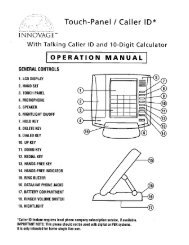
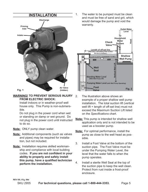
Intake<br />
Fig. 1<br />
Priming<br />
Inlet<br />
SKU <strong>2955</strong><br />
InstallatIon<br />
discharge<br />
air Valve<br />
(hidden)<br />
warnIng! to PreVent serIous InjurY<br />
From eleCtrIC sHoCK:<br />
Install indoors or in weather-proof <strong>well</strong><br />
house only. This Pump is non-submersible.<br />
Do not plug in the power cord when wet<br />
or standing on damp or wet ground. Do<br />
not plug in the power cord until instructed<br />
to do so.<br />
note: ONLY pump clean water.<br />
note: Additional components (such as valves<br />
and pipes) may be required for installation,<br />
but not included.<br />
note: Installation requires skilled workmanship<br />
and compliance with local building<br />
codes. If you are not confident in your<br />
ability to properly and safely install<br />
this pump, have a qualified technician<br />
perform the installation.<br />
reV 05l, 07g, 09d<br />
The water to be pumped must be clean<br />
and must be free of sand and grit, which<br />
would damage the pump and void the<br />
warranty.<br />
For technical questions, please call 1-800-444-3353.<br />
1.<br />
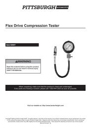
<strong>well</strong><br />
seal<br />
standing water level<br />
(with <strong>well</strong> Pump off)<br />
Foot<br />
Valve<br />
Check<br />
Valve<br />
length of off-set line<br />
(add when calculating total suction<br />
lift due to friction.)<br />
sloPe slIgHtlY downward to <strong>well</strong><br />
to<br />
Household<br />
water<br />
system<br />
Vertical <strong>well</strong> lift<br />
shallow<br />
<strong>well</strong> Pump<br />
Pumping water level (with <strong>well</strong> Pump operating)<br />
outlet water<br />
level<br />
Head<br />
Fig. 2<br />
2. The illustration above shows an<br />
example of a proper shallow <strong>well</strong> pump<br />
installation. The total suction lift (vertical<br />
<strong>well</strong> lift + length of off-set line) must not<br />
exceed the Maximum Suction Lift listed<br />
on the Specifications chart.<br />
note: This pump is intended for shallow <strong>well</strong><br />
application only and is not intended to be<br />
used as a booster pump.<br />
note: For optimal performance, install the<br />
pump as close to the <strong>well</strong> head as possible.<br />
3.<br />
4.<br />
Install a Foot Valve at the bottom of the<br />
suction pipe. The Foot Valve must be<br />
under the Pumping Water Level, the<br />
level that the water falls to when the<br />
pump operates.<br />
Install a sterile Well Seal at the top of<br />
the suction pipe to keep the <strong>well</strong> clean.<br />
Protect from rust inside a frost-proof<br />
enclosure.<br />
Page 5