3/4 HP, 1†Cast Iron sHallow well PumP 2955 ... - Harbor Freight Tools
3/4 HP, 1†Cast Iron sHallow well PumP 2955 ... - Harbor Freight Tools
3/4 HP, 1†Cast Iron sHallow well PumP 2955 ... - Harbor Freight Tools

You also want an ePaper? Increase the reach of your titles
YUMPU automatically turns print PDFs into web optimized ePapers that Google loves.
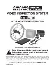
3/4 <strong>HP</strong>, 1” <strong>Cast</strong> <strong>Iron</strong> <strong>sHallow</strong><br />
<strong>well</strong> <strong>PumP</strong><br />
<strong>2955</strong><br />
set uP and oPeratIng InstruCtIons<br />
Visit our website at: http://www.harborfreight.com<br />
read this material before using this product.<br />
Failure to do so can result in serious injury.<br />
saVe tHIs manual.<br />
Copyright © 2002 by <strong>Harbor</strong> <strong>Freight</strong> <strong>Tools</strong> ® . All rights reserved. No portion of this manual or any artwork contained<br />
herein may be reproduced in any shape or form without the express written consent of <strong>Harbor</strong> <strong>Freight</strong> <strong>Tools</strong>.<br />
Diagrams within this manual may not be drawn proportionally. Due to continuing improvements, actual product may<br />
differ slightly from the product described herein. <strong>Tools</strong> required for assembly and service may not be included.<br />
For technical questions or replacement parts, please call 1-800-444-3353.<br />
Revised Manual 08i; 09f, 09k
saVe tHIs manual<br />
Keep this manual for the safety warnings<br />
and precautions, assembly, operating, inspection,<br />
maintenance and cleaning procedures.<br />
Write the product’s serial number in the back<br />
of the manual near the assembly diagram (or<br />
month and year of purchase if product has no<br />
number). Keep this manual and the receipt in<br />
a safe and dry place for future reference.<br />
ImPortant saFetY<br />
InFormatIon<br />
In this manual, on the labeling, and<br />
all other information provided with<br />
this product:<br />
reV 06c; 07g<br />
SKU <strong>2955</strong><br />
this is the safety alert symbol.<br />
It is used to alert you<br />
to potential personal injury<br />
hazards. obey all safety messages<br />
that follow this symbol<br />
to avoid possible injury or<br />
death.<br />
danger indicates a<br />
hazardous situation<br />
which, if not avoided, will result<br />
in death or serious injury.<br />
warnIng indicates a<br />
hazardous situation<br />
which, if not avoided, could<br />
result in death or serious injury.<br />
CautIon, used with<br />
the safety alert<br />
symbol, indicates a hazardous<br />
situation which, if not avoided,<br />
could result in minor or moderate<br />
injury.<br />
notICe is used to<br />
address practices not<br />
related to personal injury.<br />
For technical questions, please call 1-800-444-3353.<br />
CautIon, without the<br />
safety alert symbol, is<br />
used to address practices not<br />
related to personal injury.<br />
saFetY warnIngs and<br />
PreCautIons<br />
warnIng read all safety warnings<br />
and instructions. Failure to follow the<br />
warnings and instructions may result<br />
in electric shock, fire and/or serious<br />
injury.<br />
save all warnings and instructions<br />
for future reference.<br />
read all instructions before use!<br />
1. Keep work area clean.<br />
Cluttered areas<br />
invite injuries.<br />
2. observe work area conditions.<br />
Do not<br />
expose this pump to rain or submerge<br />
in water. Keep work area <strong>well</strong> lighted.<br />
Do not use electrically powered pumps<br />
in the presence of flammable gases or<br />
liquids.<br />
3. Keep children away.<br />
Children must<br />
never be allowed in the work area. Do<br />
not let them handle Pump.<br />
4. use the right pump for the job.<br />
Do<br />
not attempt to force a small Pump to<br />
do the work of a larger industrial Pump.<br />
There are certain applications for which<br />
this Pump was designed. It will do the<br />
job better and more safely at the rate for<br />
which it was intended. Do not modify<br />
this Pump and do not use this Pump for<br />
a purpose for which it was not intended.<br />
5. dress properly.<br />
Do not wear loose<br />
clothing or jewelry as they can be caught<br />
in moving parts. Protective, electrically<br />
non-conductive clothes and non-skid<br />
footwear are recommended when working.<br />
Wear restrictive hair covering to<br />
contain long hair.<br />
Page 2
6. use eye and ear protection.<br />
Wear<br />
ANSI-approved impact safety goggles<br />
and ear protection.<br />
7. do not overreach.<br />
Keep proper footing<br />
and balance at all times. Do not reach<br />
over or across running machines.<br />
8. maintain Pump with care.<br />
Keep Pump<br />
clean for better and safer performance.<br />
Inspect pump cords periodically; If damaged,<br />
have them repaired by a qualified<br />
technician.<br />
9. disconnect power.<br />
Unplug Pump when<br />
not in use.<br />
10. stay alert.<br />
Watch what you are doing,<br />
use common sense. Do not install Pump<br />
when you are tired.<br />
11. Check for damaged parts.<br />
Before using<br />
Pump, any part that appears damaged<br />
should be carefully checked to<br />
determine that it will operate properly<br />
and perform its intended function. Check<br />
for alignment and binding of moving<br />
parts; any broken parts or mounting fixtures;<br />
and any other condition that may<br />
affect proper operation. Any part that is<br />
damaged should be properly repaired or<br />
replaced by a qualified technician.<br />
12. replacement parts and accessories.<br />
When servicing, use only identical replacement<br />
parts. Use of any other parts<br />
will void the warranty.<br />
13.<br />
Do not install Pump if under the influence<br />
of alcohol or drugs. Read warning<br />
labels on prescriptions to determine<br />
if your judgment or reflexes are impaired<br />
while taking drugs. If there is any doubt,<br />
do not install the Pump.<br />
reV 07g; 08j, 09d<br />
SKU <strong>2955</strong><br />
14.<br />
reCommended mInImum wIre<br />
gauge For eXtensIon Cords<br />
(120 Volt)<br />
namePlate<br />
amPeres<br />
(at full load)<br />
For technical questions, please call 1-800-444-3353.<br />
eXtensIon Cord<br />
lengtH<br />
25’ 50’ 100’ 150’<br />
0 – 6 18 16 16 14<br />
6.1 – 10 18 16 14 12<br />
10.1 – 12 16 16 14 12<br />
12.1 – 16 14 12 do not use.<br />
taBle a<br />
USE PROPER EXTENSION CORD.<br />
Make sure your extension cord is in<br />
good condition. When using an extension<br />
cord, be sure to use one heavy<br />
enough to carry the current your product<br />
will draw. An undersized cord will<br />
cause a drop in line voltage resulting in<br />
loss of power and overheating. Table A<br />
shows the correct size to use depending<br />
on cord length and nameplate ampere<br />
rating. If in doubt, use the next heavier<br />
gauge. The smaller the gauge number,<br />
the heavier the cord.<br />
15. maintenance.<br />
For your safety, maintenance<br />
should be performed regularly by<br />
a qualified technician.<br />
16. Pump clean water only. Do not use the<br />
pump for any other application.<br />
17.<br />
18.<br />
19.<br />
People with pacemakers should consult<br />
their physician(s) before use. Electromagnetic<br />
fields in close proximity to<br />
heart pacemaker could cause pacemaker<br />
interference or pacemaker failure.<br />
The brass components of this product<br />
contain lead, a chemical known to the<br />
State of California to cause birth defects<br />
(or other reproductive harm). (California<br />
Health & Safety code § 25249.5, et seq.)<br />
do not operate this pump if the power<br />
cord or electrical components are<br />
damaged or the seals are compromised.<br />
do not plug in the power cord<br />
Page 3
when wet or standing on damp or wet<br />
ground. exercise caution when working<br />
with electrical equipment in the<br />
presence of water to maintain your<br />
personal insulation to avoid shock.<br />
use gFCI (ground Fault Circuit Interrupter)<br />
outlets when using this pump.<br />
20. warnIng: Handling the cord on this<br />
product will expose you to lead, a chemical<br />
known to the State of California to<br />
cause cancer, and birth defects or other<br />
reproductive harm. Wash hands after<br />
handling.<br />
(California Health & Safety Code §<br />
25249.5, et seq.)<br />
21.<br />
the warnings, cautions, and instructions<br />
discussed in this instruction<br />
manual cannot cover all possible conditions<br />
and situations that may occur.<br />
It must be understood by the operator<br />
that common sense and caution are<br />
factors which cannot be built into this<br />
product, but must be supplied by the<br />
operator.<br />
SKU <strong>2955</strong><br />
unPaCKIng<br />
When unpacking, make sure the item is<br />
intact and undamaged. If any parts are missing<br />
or broken, please call <strong>Harbor</strong> <strong>Freight</strong> <strong>Tools</strong><br />
at 1-800-444-3353 as soon as possible.<br />
sPeCIFICatIons<br />
Power Requirements 120 V~, 60 Hz, 3/4 <strong>HP</strong><br />
Motor Speed 3400 RPM<br />
Discharge/Intake 1” NPT<br />
Max. Flow 900 GPH<br />
Max. Suction Lift 26’<br />
Max. Total Head 140’<br />
Tank Size 5 Gallons<br />
Pump Body Material <strong>Cast</strong> <strong>Iron</strong><br />
Cut-in Pressure 20 PSI<br />
Cut-out Pressure 50 PSI<br />
note: Performance of this pump (if powered<br />
by line voltage) may vary depending on<br />
variations in local line voltage. Extension<br />
cord usage may also affect pump performance.<br />
For technical questions, please call 1-800-444-3353.<br />
Page 4
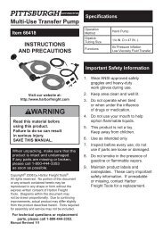
Intake<br />
Fig. 1<br />
Priming<br />
Inlet<br />
SKU <strong>2955</strong><br />
InstallatIon<br />
discharge<br />
air Valve<br />
(hidden)<br />
warnIng! to PreVent serIous InjurY<br />
From eleCtrIC sHoCK:<br />
Install indoors or in weather-proof <strong>well</strong><br />
house only. This Pump is non-submersible.<br />
Do not plug in the power cord when wet<br />
or standing on damp or wet ground. Do<br />
not plug in the power cord until instructed<br />
to do so.<br />
note: ONLY pump clean water.<br />
note: Additional components (such as valves<br />
and pipes) may be required for installation,<br />
but not included.<br />
note: Installation requires skilled workmanship<br />
and compliance with local building<br />
codes. If you are not confident in your<br />
ability to properly and safely install<br />
this pump, have a qualified technician<br />
perform the installation.<br />
reV 05l, 07g, 09d<br />
The water to be pumped must be clean<br />
and must be free of sand and grit, which<br />
would damage the pump and void the<br />
warranty.<br />
For technical questions, please call 1-800-444-3353.<br />
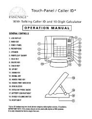
1.<br />
<strong>well</strong><br />
seal<br />
standing water level<br />
(with <strong>well</strong> Pump off)<br />
Foot<br />
Valve<br />
Check<br />
Valve<br />
length of off-set line<br />
(add when calculating total suction<br />
lift due to friction.)<br />
sloPe slIgHtlY downward to <strong>well</strong><br />
to<br />
Household<br />
water<br />
system<br />
Vertical <strong>well</strong> lift<br />
shallow<br />
<strong>well</strong> Pump<br />
Pumping water level (with <strong>well</strong> Pump operating)<br />
outlet water<br />
level<br />
Head<br />
Fig. 2<br />
2. The illustration above shows an<br />
example of a proper shallow <strong>well</strong> pump<br />
installation. The total suction lift (vertical<br />
<strong>well</strong> lift + length of off-set line) must not<br />
exceed the Maximum Suction Lift listed<br />
on the Specifications chart.<br />
note: This pump is intended for shallow <strong>well</strong><br />
application only and is not intended to be<br />
used as a booster pump.<br />
note: For optimal performance, install the<br />
pump as close to the <strong>well</strong> head as possible.<br />
3.<br />
4.<br />
Install a Foot Valve at the bottom of the<br />
suction pipe. The Foot Valve must be<br />
under the Pumping Water Level, the<br />
level that the water falls to when the<br />
pump operates.<br />
Install a sterile Well Seal at the top of<br />
the suction pipe to keep the <strong>well</strong> clean.<br />
Protect from rust inside a frost-proof<br />
enclosure.<br />
Page 5
5.<br />
6.<br />
7.<br />
Intake and discharge pipes must be at<br />
least 1” in diameter.<br />
Lay an off-set line from the <strong>well</strong> to the<br />
structure the pump will be installed in.<br />
The off-set line should slope slightly<br />
towards the <strong>well</strong> (see Fig. 2). Systems<br />
with longer off-set lines should use larger<br />
diameter pipe to improve efficiency.<br />
Install the pump on a rigid, level, dry<br />
platform. This platform must provide a<br />
solid, level surface that is capable of<br />
supporting the weight of the pump and<br />
attached piping filled with water. Do<br />
not allow water to contact the pump’s<br />
housing.<br />
Caution: DO NOT INSERT fittings into the<br />
Intake Hole farther than 1/2”; this can<br />
DAMAGE the Pump, diminish Pump<br />
functions, and/or STOP water flow.<br />
8.<br />
9.<br />
10.<br />
reV 09d<br />
Keep the Head, the height that the<br />
pump discharge must push water before<br />
discharge, to a minimum. The Vertical<br />
Well Lift, Off-set Line Length, and Head<br />
added together must be less than Max.<br />
Total Head to have flow at output.<br />
Effective flow decreases to 0 GPH as<br />
Total Head reaches its maximum.<br />
For your protection, the power outlet<br />
used should have a Ground Fault Circuit<br />
Interrupter (GFCI). Have it installed by<br />
a qualified electrician. Keep power line<br />
away from water.<br />
The inlet and discharge lines should not<br />
be wedged or stressed in a way that puts<br />
strain on the pump. Do not support the<br />
pump with the inlet and discharge lines.<br />
SKU <strong>2955</strong><br />
For technical questions, please call 1-800-444-3353.<br />
Page 6
1.<br />
2.<br />
3.<br />
4.<br />
5.<br />
SKU <strong>2955</strong><br />
oPeratIon<br />
Compression Tank has a rubber bladder<br />
inside. This bladder must be pumped<br />
up to 26-29 PSI of air at all times. Use a<br />
bicycle pump (not included) to inflate the<br />
bladder. On the end of the Compression<br />
Tank opposite the side with the Pressure<br />
Meter, is an air valve located under a<br />
cover. Remove the cover over the air<br />
valve and periodically monitor this air<br />
valve with an air pressure gauge to<br />
insure that the rubber bladder maintains<br />
the required air pressure.<br />
Make sure the intake pipe is fully<br />
submerged before continuing.<br />
Before starting the pump for the first<br />
time, prime it by pouring clean water<br />
into the Priming Inlet.<br />
This is a self-starting pump that uses a<br />
pressure switch. Once the power cord<br />
is connected and the unit is switched on,<br />
the pump can start at any time. do not<br />
handle or perform maintenance on the<br />
pump if the power cord is plugged in.<br />
To begin pumping, plug in the power<br />
cord and turn the switch on. When the<br />
line is pressurized, the pump will go to<br />
standby mode until the pressure falls<br />
below its starting pressure.<br />
For technical questions, please call 1-800-444-3353.<br />
Page 7
eV 06c; 07g; 07l; 08l; 09d<br />
SKU <strong>2955</strong><br />
maIntenanCe<br />
warnIng! disconnect pump from power<br />
source before maintenance.<br />
1.<br />
2.<br />
Clean the inlet screen on the intake port<br />
regularly to remove accumulated debris.<br />
Wipe the pump clean with a soft, damp<br />
cloth with soapy water. Do not use solvents.<br />
Do not get the electrical components<br />
wet.<br />
Drain water from pump before storage<br />
by disconnecting the water lines and<br />
turning the Pump upside down. If storing<br />
the pump for a long time, store it in a dry<br />
location, and apply a light layer of oil to<br />
the metal parts prior to storage, to inhibit<br />
rust. do not expose to freezing temperatures.<br />
For technical questions, please call 1-800-444-3353.<br />
3.<br />
4.<br />
troubleshooting<br />
After storage, check the Impeller to make<br />
sure it turns easily and is not oxidized.<br />
note: Turn off the switch and unplug the<br />
pump when performing maintenance.<br />
Problem Cause solution<br />
The pump won’t start 1. No power.<br />
1. Check connections, and breaker/fuse.<br />
The pump operates<br />
but it won’t discharge<br />
water<br />
Only a low volume of<br />
water flows<br />
2.<br />
3.<br />
Pressure switch disconnected.<br />
Thermal Protection cut out.<br />
4. Blocked impeller.<br />
1. Pump not primed.<br />
2.<br />
3.<br />
4.<br />
Lift height exceeded.<br />
Inlet tube not submerged.<br />
Air in suction pipe.<br />
5. Inlet screen clogged.<br />
1. Inlet pipe is too small.<br />
2.<br />
3.<br />
4.<br />
5.<br />
Liquid is too dirty.<br />
Lifting height exceeded.<br />
Tank’s rubber bladder under-inflated.<br />
Piping corroded, causing friction.<br />
Motor overheats often 1. Extension cord too long or wire size too<br />
small.<br />
Pump/motor cycles<br />
rapidly<br />
Tank bladder will not<br />
hold pressure<br />
Water pumps<br />
intermittently<br />
2.<br />
Pump cycling too often.<br />
Cut-in and cut-out pressure may be set too<br />
closely.<br />
1. Air inlet valve is leaking.<br />
2.<br />
3.<br />
Check gauge.<br />
Allow pump to cool.<br />
4. Free the impeller.<br />
1. Prime pump.<br />
2.<br />
3.<br />
4.<br />
Reduce lift height.<br />
Submerge the inlet.<br />
Check pipe and seals.<br />
5. Clean screen.<br />
1. Increase pipe diameter.<br />
2.<br />
3.<br />
4.<br />
Clean screen frequently.<br />
Reduce lifting height.<br />
Inflate to 26-29 PSI.<br />
2. Bladder is broken.<br />
2. Replace bladder.<br />
Water level is being drawn below foot valve. Lower foot valve.<br />
5. Replace piping, with plastic where<br />
possible.<br />
1. Eliminate use of extension cord or use<br />
shorter/heavier gauge cord.<br />
2. Cut-in and cut-out pressure may be set<br />
too closely; Have the pressure switch<br />
adjusted by a qualified technician.<br />
Have the pressure switch adjusted by a<br />
qualified technician.<br />
1. Check air tank for leaks using soapy<br />
water and replace bladder if needed.<br />
Follow all safety precautions whenever diagnosing or servicing the pump.<br />
disconnect power supply before service.<br />
do not disassemble the pump or motor as this will damage the water seals.<br />
All repairs should be performed by a qualified technician.<br />
Page 8
Problem Cause solution<br />
Pump will not hold 1. Foot/check valve not installed in suction 1. Install foot and check valve in suction<br />
prime<br />
line.<br />
line.<br />
Water is full of<br />
bubbles at outlet<br />
Motor runs, but water<br />
is not pumping<br />
Pump does not shutoff<br />
SKU <strong>2955</strong><br />
2. Foot/check valve leaks water back to <strong>well</strong>. 2. Replace foot/check valve.<br />
1. Pumping bubbles temporarily as air is<br />
purged after initial setup.<br />
1. Temporary self-remedying issue.<br />
2.<br />
3.<br />
Leak in suction side of pump system.<br />
Well is gaseous.<br />
4. Water level below suction inlet of foot<br />
valve.<br />
1.<br />
2.<br />
3.<br />
Improper priming.<br />
Air leakage.<br />
Vertical lift too high.<br />
4. Water level below suction inlet of foot<br />
valve.<br />
5.<br />
6.<br />
7.<br />
Frozen pipes.<br />
Foot valve in dirt or sand.<br />
Foot/check valve clogged.<br />
Check for and fix leaks.<br />
Please read tHe FollowIng CareFullY<br />
THE MANUFACTURER AND/OR DISTRIBUTOR HAS PROVIDED THE PARTS LIST AND ASSEMBLY<br />
DIAGRAM IN THIS MANUAL AS A REFERENCE TOOL ONLY. NEITHER THE MANUFACTURER OR<br />
DISTRIBUTOR MAKES ANY REPRESENTATION OR WARRANTY OF ANY KIND TO THE BUYER THAT HE<br />
OR SHE IS qUALIFIED TO MAKE ANY REPAIRS TO THE PRODUCT, OR THAT HE OR SHE IS qUALIFIED<br />
TO REPLACE ANY PARTS OF THE PRODUCT. IN FACT, THE MANUFACTURER AND/OR DISTRIBUTOR<br />
EXPRESSLY STATES THAT ALL REPAIRS AND PARTS REPLACEMENTS SHOULD BE UNDERTAKEN BY<br />
CERTIFIED AND LICENSED TECHNICIANS, AND NOT BY THE BUYER. THE BUYER ASSUMES ALL RISK<br />
AND LIABILITY ARISING OUT OF HIS OR HER REPAIRS TO THE ORIGINAL PRODUCT OR REPLACEMENT<br />
PARTS THERETO, OR ARISING OUT OF HIS OR HER INSTALLATION OF REPLACEMENT PARTS THERETO.<br />
For technical questions, please call 1-800-444-3353.<br />
2.<br />
3.<br />
Install a sleeve in the <strong>well</strong>.<br />
4. Lower suction line into water and reprime.<br />
If water is deeper than 26 ft,<br />
then a deep <strong>well</strong> pump may be needed.<br />
1. Prime the pump by pouring clean water<br />
into the Priming Inlet.<br />
2. Check all pipes and joints in the suction<br />
line for air leakage using soapy water.<br />
3. Reduce vertical lift to within<br />
specifications. See Installation<br />
instructions.<br />
4. Lower suction line into water and reprime.<br />
If water is deeper than 26 ft,<br />
then a deep <strong>well</strong> pump may be needed.<br />
5. Thaw the pipes. Bury pipes below<br />
freeze line/insulate pipes.<br />
6.<br />
7.<br />
Raise foot valve to clean water level.<br />
Clean or replace foot/check valve.<br />
8. Pressure switch is set too low.<br />
8. Have the pressure switch adjusted by<br />
qualified technician (20-50 psi).<br />
1. Pressure switch contacts welded together. 1. Have the pressure switch replaced by a<br />
qualified technician.<br />
2.<br />
3.<br />
4.<br />
5.<br />
6.<br />
7.<br />
Faucet is open or leaking.<br />
Toilet leaking.<br />
Impeller is clogged.<br />
Tank bladder pressure is too low.<br />
Pipeline leakage.<br />
Foot/check valve leaks water back to <strong>well</strong>.<br />
2.<br />
3.<br />
4.<br />
5.<br />
6.<br />
Close or repair faucet.<br />
Repair leaky toilet.<br />
Clean impeller.<br />
Inflate to 26-29 psi.<br />
Repair pipeline.<br />
Replace foot/check valve.<br />
Follow all safety precautions whenever diagnosing or servicing the pump.<br />
disconnect power supply before service.<br />
do not disassemble the pump or motor as this will damage the water seals.<br />
All repairs should be performed by a qualified technician.<br />
7.<br />
Page 9
Part description Qty.<br />
1* Hex Screw 4<br />
2* Motor Cover 1<br />
3* Fan Blade 1<br />
4* Rear Cover 1<br />
5* Spring Washer 1<br />
6* Bolt 4<br />
7* Stator 1<br />
8* Bearing (rear) 1<br />
9* Rotor 1<br />
10* Bearing (front) 1<br />
11* Connecting Screw 4<br />
12* Front Cover 1<br />
13 Rubber Ring 1<br />
14 O-ring 1<br />
15 Flange 1<br />
16 O-ring 1<br />
17 Impeller 1<br />
18 Flow Guide Plate 1<br />
19 O-ring 1<br />
20 Flow Guide Assembly 1<br />
21 O-ring 1<br />
22 Pump Shell 1<br />
23 Priming Plug 1<br />
25 O-ring 1<br />
27 Switch 1<br />
28 Pressure Meter 1<br />
29 Seal Lining 1<br />
SKU <strong>2955</strong><br />
Parts lIst<br />
Part description Qty.<br />
30 Cord and Plug 1<br />
31 Tube 1<br />
32 Rubber Sheath 1<br />
33 Seal Lining 1<br />
34 O-ring 1<br />
35 Tank 1<br />
36 Hex Bolt 2<br />
37 Hex Nut 1 2<br />
38 Rubber Sheath 3<br />
39* Capacitor Fastener 1<br />
40* Capacitor 1<br />
41* Self Tapping Screw 2<br />
42* Cable Pressing Block 1<br />
43* Cable Sleeve 1<br />
44* Self Tapping Screw 3<br />
45* Switch 1<br />
47* Side Cover 1<br />
48* Isolate Cover 1<br />
49* Connecting Cable 1<br />
50 Motor Kit 1<br />
51 Bladder inside Tank and Air Valve 1<br />
52 Retaining Ring 1<br />
54 Small Bushing 2<br />
55 Sealing 1<br />
56^ PTFE Thread Seal Tape Roll 1<br />
57^ Foot Valve 1<br />
58^ Check Valve 1<br />
* Parts marked with an asterisk (*) may only be purchased as part of the motor Kit (50).<br />
They cannot be purchased separately.<br />
^ Parts marked with a caret (^) are not shown on the diagram.<br />
record Product’s serial number Here:<br />
note: If product has no serial number, record month and year of purchase instead.<br />
note: Some parts are listed and shown for illustration purposes only, and are not available<br />
individually as replacement parts.<br />
reV 03e, 09c<br />
For technical questions, please call 1-800-444-3353.<br />
Page 10
eV 03e, 09c<br />
SKU <strong>2955</strong><br />
assemBlY drawIng<br />
For technical questions, please call 1-800-444-3353.<br />
Page 11
eV 07g<br />
SKU <strong>2955</strong><br />
lImIted 1 Year / 90 daY warrantY<br />
<strong>Harbor</strong> <strong>Freight</strong> <strong>Tools</strong> Co. makes every effort to assure that its products meet high quality<br />
and durability standards, and warrants to the original purchaser that for a period of ninety<br />
days from date of purchase that the engine/motor, the belts (if so equipped), and the blades<br />
(if so equipped) are free of defects in materials and workmanship. <strong>Harbor</strong> <strong>Freight</strong> <strong>Tools</strong> also<br />
warrants to the original purchaser, for a period of one year from date of purchase, that all other<br />
parts and components of the product are free from defects in materials and workmanship (90<br />
days if used by a professional contractor or if used as rental equipment). This warranty does<br />
not apply to damage due directly or indirectly, to misuse, abuse, negligence or accidents, repairs<br />
or alterations outside our facilities, normal wear and tear, or to lack of maintenance. We<br />
shall in no event be liable for death, injuries to persons or property, or for incidental, contingent,<br />
special or consequential damages arising from the use of our product. Some states do not<br />
allow the exclusion or limitation of incidental or consequential damages, so the above limitation<br />
of exclusion may not apply to you. THIS WARRANTY IS EXPRESSLY IN LIEU OF ALL<br />
OTHER WARRANTIES, EXPRESS OR IMPLIED, INCLUDING THE WARRANTIES OF MER-<br />
CHANTABILITY AND FITNESS.<br />
To take advantage of this warranty, the product or part must be returned to us with transportation<br />
charges prepaid. Proof of purchase date and an explanation of the complaint must<br />
accompany the merchandise. If our inspection verifies the defect, we will either repair or replace<br />
the product at our election or we may elect to refund the purchase price if we cannot<br />
readily and quickly provide you with a replacement. We will return repaired products at our expense,<br />
but if we determine there is no defect, or that the defect resulted from causes not within<br />
the scope of our warranty, then you must bear the cost of returning the product.<br />
This warranty gives you specific legal rights and you may also have other rights which<br />
vary from state to state.<br />
3491 Mission Oaks Blvd. • PO Box 6009 • Camarillo, CA 93011 • (800) 444-3353<br />
For technical questions, please call 1-800-444-3353.<br />
Page 12