LM3445 Triac Dimmable Offline LED Driver
LM3445 Triac Dimmable Offline LED Driver LM3445 Triac Dimmable Offline LED Driver
LM3445 Application Information FUNCTIONAL DESCRIPTION The LM3445 contains all the necessary circuitry to build a linepowered (mains powered) constant current LED driver whose output current can be controlled with a conventional triac dimmer. OVERVIEW OF PHASE CONTROL DIMMING A basic "phase controlled" triac dimmer circuit is shown in Figure 2. 30060312 FIGURE 2. Basic Triac Dimmer An RC network consisting of R1, R2, and C1 delay the turn on of the triac until the voltage on C1 reaches the trigger voltage of the diac. Increasing the resistance of the potentiometer (wiper moving downward) increases the turn-on delay which decreases the on-time or "conduction angle" of the triac (θ). This reduces the average power delivered to the load. Voltage waveforms for a simple triac dimmer are shown in Figure 3. Figure 3a shows the full sinusoid of the input voltage. Even when set to full brightness, few dimmers will provide 100% on-time, i.e., the full sinusoid. FIGURE 3. Line Voltage and Dimming Waveforms 30060313 Figure 3b shows a theoretical waveform from a dimmer. The on-time is often referred to as the "conduction angle" and may be stated in degrees or radians. The off-time represents the delay caused by the RC circuit feeding the triac. The off-time be referred to as the "firing angle" and is simply 180° - θ. Figure 3c shows a waveform from a so-called reverse phase dimmer, sometimes referred to as an electronic dimmer. These typically are more expensive, microcontroller based dimmers that use switching elements other than triacs. Note that the conduction starts from the zero-crossing, and terminates some time later. This method of control reduces the noise spike at the transition. Since the LM3445 has been designed to assess the relative on-time and control the LED current accordingly, most phasecontrol dimmers, both forward and reverse phase, may be used with success. www.national.com 8
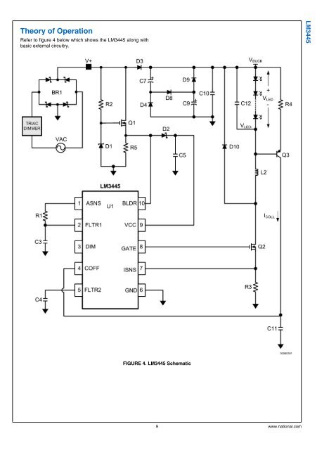
Theory of Operation Refer to figure 4 below which shows the LM3445 along with basic external circuitry. LM3445 30060301 FIGURE 4. LM3445 Schematic 9 www.national.com
- Page 1 and 2: LM3445 Triac Dimmable Offline LED D
- Page 3 and 4: Absolute Maximum Ratings (Notes 1,
- Page 5 and 6: Typical Performance Characteristics
- Page 7: Simplified Internal Block Diagram L
- Page 11 and 12: performance vs efficiency. As the h
- Page 13 and 14: LM3445 30060323 FIGURE 11. LM3445 B
- Page 15 and 16: MASTER/SLAVE CONNECTION DIAGRAM LM3
- Page 17 and 18: Design Guide DETERMINING DUTY-CYCLE
- Page 19 and 20: SETTING THE LED CURRENT The LM3445
- Page 21 and 22: capacitors are delivering power to
- Page 23 and 24: LM3445 Design Example 1: Input = 90
- Page 25 and 26: Physical Dimensions inches (millime
Theory of Operation<br />
Refer to figure 4 below which shows the <strong>LM3445</strong> along with<br />
basic external circuitry.<br />
<strong>LM3445</strong><br />
30060301<br />
FIGURE 4. <strong>LM3445</strong> Schematic<br />
9 www.national.com


