Volume 2-05, Chapter 3 - City of Wichita
Volume 2-05, Chapter 3 - City of Wichita
Volume 2-05, Chapter 3 - City of Wichita

Create successful ePaper yourself
Turn your PDF publications into a flip-book with our unique Google optimized e-Paper software.
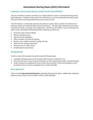
Section 3.3.5 - Organic Filter<br />
• Organic filters can utilize a variety <strong>of</strong> organic materials as the filtering media. Two typical<br />
media bed configurations are the peat/sand filter and compost filter (see Figure 3-52). The<br />
peat filter includes an 18-inch 50/50 peat/sand mix over a 6-inch sand layer and can be<br />
optionally by 3 inches <strong>of</strong> topsoil and vegetation for aesthetic purposes. The compost filter<br />
has an 18-inch compost layer. Both variants utilize a gravel underdrain system.<br />
• The type <strong>of</strong> peat used in a peat/sand filter is critically important. Fibric peat in which<br />
undecomposed fibrous organic material is readily identifiable is the preferred type. Hemic<br />
peat containing more decomposed material may also be used. Sapric peat made up <strong>of</strong><br />
largely decomposed matter should not be used in an organic filter.<br />
• Typically, organic filters are designed as "<strong>of</strong>f-line" systems, meaning that the WQ v is<br />
diverted to the filter facility through the use <strong>of</strong> a flow diversion structure and flow splitter.<br />
Stormwater flows greater than the WQ v are diverted to other controls or downstream using<br />
a diversion structure or flow splitter.<br />
• Consult the design criteria for the surface sand filter (see Section 3.2.8) for the organic<br />
filter siting requirements, and sizing/design steps. The following permeability values may<br />
be used: sand = 3.5 ft/day, peat = 2.0 ft/day, and leaf compost = 8.5 ft/day. A porosity <strong>of</strong><br />
0.4 may be assumed.<br />
• The local jurisdiction may require that the facility be placed in a reserve and/or<br />
establishment <strong>of</strong> a drainage easement the facility, which is accessible from a public road<br />
or other accessible easement. When required, the drainage easement should be at least<br />
20 feet wide, provide a minimum traversable width <strong>of</strong> 15 feet, have a maximum slope <strong>of</strong> no<br />
more than 10%, and be appropriately stabilized to withstand maintenance equipment and<br />
vehicles.<br />
• A minimum separation distance <strong>of</strong> 5 feet is required between the bottom <strong>of</strong> the filter and<br />
the elevation <strong>of</strong> the historical high water table for filter without underdrains, 2 feet for filters<br />
with underdrains.<br />
3.3.5.4 Inspection and Maintenance Requirements<br />
Regular inspection and maintenance is critical to the effective operation <strong>of</strong> stormwater<br />
management facilities. An operation and maintenance plan is required and shall include:<br />
1. “Covenants for Permanent Maintenance <strong>of</strong> Stormwater Management Facilities” (also<br />
called the “Maintenance Covenants”). An example covenants document can be found in<br />
<strong>Volume</strong> 3.<br />
2. “Inspection Checklist and Maintenance Guidance” for each type <strong>of</strong> stormwater facility that<br />
is located on the property. Templates for each stormwater management facility can be<br />
found in <strong>Volume</strong> 3 <strong>of</strong> this manual. These templates can be amended slightly for use in<br />
more customized O&M plans.<br />
3. As-built drawings must accurately identify the location <strong>of</strong> the facility, and also clearly<br />
identify reserves and access easements.<br />
<strong>Volume</strong> 2, Technical Guidance Page 3 - 177