Volume 2-05, Chapter 3 - City of Wichita
Volume 2-05, Chapter 3 - City of Wichita
Volume 2-05, Chapter 3 - City of Wichita

Create successful ePaper yourself
Turn your PDF publications into a flip-book with our unique Google optimized e-Paper software.
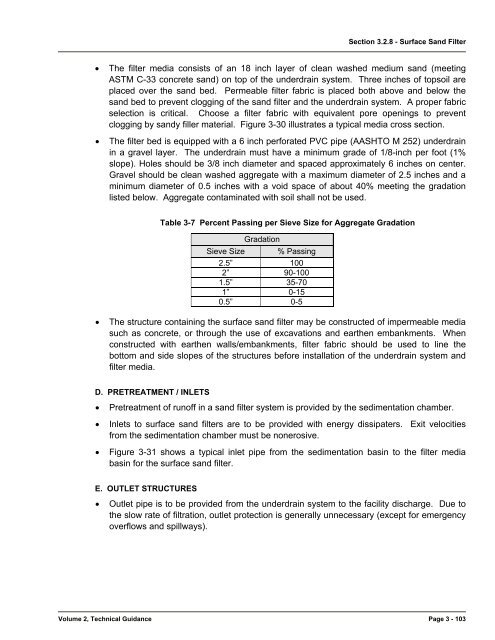
Section 3.2.8 - Surface Sand Filter<br />
• The filter media consists <strong>of</strong> an 18 inch layer <strong>of</strong> clean washed medium sand (meeting<br />
ASTM C-33 concrete sand) on top <strong>of</strong> the underdrain system. Three inches <strong>of</strong> topsoil are<br />
placed over the sand bed. Permeable filter fabric is placed both above and below the<br />
sand bed to prevent clogging <strong>of</strong> the sand filter and the underdrain system. A proper fabric<br />
selection is critical. Choose a filter fabric with equivalent pore openings to prevent<br />
clogging by sandy filler material. Figure 3-30 illustrates a typical media cross section.<br />
• The filter bed is equipped with a 6 inch perforated PVC pipe (AASHTO M 252) underdrain<br />
in a gravel layer. The underdrain must have a minimum grade <strong>of</strong> 1/8-inch per foot (1%<br />
slope). Holes should be 3/8 inch diameter and spaced approximately 6 inches on center.<br />
Gravel should be clean washed aggregate with a maximum diameter <strong>of</strong> 2.5 inches and a<br />
minimum diameter <strong>of</strong> 0.5 inches with a void space <strong>of</strong> about 40% meeting the gradation<br />
listed below. Aggregate contaminated with soil shall not be used.<br />
Table 3-7 Percent Passing per Sieve Size for Aggregate Gradation<br />
Gradation<br />
Sieve Size % Passing<br />
2.5” 100<br />
2” 90-100<br />
1.5” 35-70<br />
1” 0-15<br />
0.5” 0-5<br />
• The structure containing the surface sand filter may be constructed <strong>of</strong> impermeable media<br />
such as concrete, or through the use <strong>of</strong> excavations and earthen embankments. When<br />
constructed with earthen walls/embankments, filter fabric should be used to line the<br />
bottom and side slopes <strong>of</strong> the structures before installation <strong>of</strong> the underdrain system and<br />
filter media.<br />
D. PRETREATMENT / INLETS<br />
• Pretreatment <strong>of</strong> run<strong>of</strong>f in a sand filter system is provided by the sedimentation chamber.<br />
• Inlets to surface sand filters are to be provided with energy dissipaters. Exit velocities<br />
from the sedimentation chamber must be nonerosive.<br />
• Figure 3-31 shows a typical inlet pipe from the sedimentation basin to the filter media<br />
basin for the surface sand filter.<br />
E. OUTLET STRUCTURES<br />
• Outlet pipe is to be provided from the underdrain system to the facility discharge. Due to<br />
the slow rate <strong>of</strong> filtration, outlet protection is generally unnecessary (except for emergency<br />
overflows and spillways).<br />
<strong>Volume</strong> 2, Technical Guidance Page 3 - 103