Master Thesis - OUFTI-1
Master Thesis - OUFTI-1 Master Thesis - OUFTI-1
In this design, the battery Printed Circuit Board (PCB) was suspended to the xEPS card, using four T i screws. The two PCBs are separated by four T i spacers and thermal washers are placed at the level of the battery PCB to isolate it thermally. The main problem of this design was the available space between the batteries and the electronic cards situated under and above them, as it is shown in Figure 3.2. Figure 3.2: Available space under and above the batteries The available space between the lower battery and the highest component above the EPS card is given in Equation (3.2.1) and the distance between the upper battery and the highest component under the xEPS card is given in Equation (3.2.2). d Battery - EPS = 5.57 − 4.8 = 0.77 mm (3.2.1) d Battery - xEPS = 4.83 − 1.5 = 3.33 mm (3.2.2) So, it can already be noted that the position of the batteries inside the satellite is not optimal. In addition, due to the restricted value of the distances which separate these components, several problems can occured, especially concerning the vibrations. Indeed, the batteries could collide one of the two electronic cards and cause important damages on it. In addition to this restricted available space, it appeared, after a test under vacuum conditions, that the batteries bulged (as shown in Figure 3.3). This increase the problem of the available space and, moreover, can aect the electrical performance of the batteries. To avoid this problem, the solution which was investigated, was to encapsulate the batteries inside a box. 45
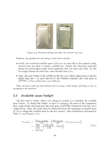
Figure 3.3: Batteries during and after the vacuum test [15] However, the problem for the design of this box is double: • Firstly, the restricted available space (2.05 mm on each side in the optimal conguration) does not allow to design a reliable box. Indeed, the vibrations generated during the launch phase might reach amplitudes that rise above this value. So, the box might damage the electronic cards situated close to it. • Then, the mass budget of the satellite in the last year's nal conguration is already higher than the 1 kg mass allowed by the CubeSat standard (the total mass of OUFTI-1 in this conguration was 1.032 kg). Thus, we had to give up this solution and to create a new design, including a box, to encapsulate the batteries. 3.3 Available mass budget The rst step to realize, when a new design is created, is to calculate the available mass budget. To obtain this budget, we have to substract the mass of the components that composed the old design from the total mass of OUFTI-1 obtained for the last year's conguration. Then, the result must be substracted from the maximum acceptable mass of 1 kg to obtain the available mass for the new support. This calculation is performed in Table 3.1 and Equation 3.3.1. m available = m max, acceptable − SF = 1000 ( 1031.4148 1.02 − 1.02 = 103.79 g ( mtot, last year − m last year SF ′ s design ) − 134.58 ) (3.3.1) 46
- Page 1 and 2: University of Liège Faculty of App
- Page 3 and 4: Abstract OUFTI-1, standing for "Orb
- Page 5 and 6: 3.4 Initial idea . . . . . . . . .
- Page 7 and 8: List of Figures 1.1 The Pumpkin's C
- Page 9 and 10: 4.18 MAC matrix using the simple me
- Page 11 and 12: List of Acronyms ADCS Al AlNiCo ASI
- Page 13 and 14: Thesis outline This thesis focuses
- Page 15 and 16: of larger satellites. So, the CubeS
- Page 17 and 18: 1.2 OUFTI-1 project 1.2.1 Genesis O
- Page 19 and 20: • XatCobeo (Vigo - Spain): Develo
- Page 21 and 22: Chapter 2 OUFTI-1: Flight system co
- Page 23 and 24: Figure 2.2: Product tree of OUFTI-1
- Page 25 and 26: 2.3.2 Solar panels The armor panels
- Page 27 and 28: • We do not want to drill or manu
- Page 29 and 30: In our case, because of the limited
- Page 31 and 32: Figure 2.13: Magnetic eld obtained
- Page 33 and 34: Figure 2.17: Pictures of the ADCS c
- Page 35 and 36: consider the possibility of oshorin
- Page 37 and 38: Figure 2.20: Exploded view of OUFTI
- Page 39 and 40: I xx , I yy and I zz are called the
- Page 41 and 42: Subsystem: Structure & Conguration
- Page 43 and 44: Subsystem: Thermal Control Parts Co
- Page 45: Chapter 3 Design of a new support f
- Page 49 and 50: The concept is the following one: F
- Page 51 and 52: A test under vacuum conditions was
- Page 53 and 54: Thermal Expansion (CTE) of the mate
- Page 55 and 56: Figure 3.9: Classication by density
- Page 57 and 58: The last property to determine is t
- Page 59 and 60: • So, it was decided to use two t
- Page 61 and 62: is to prevent the batteries' bulge.
- Page 63 and 64: • Then, the thermostats, that wil
- Page 65 and 66: Figure 3.23: Schematics of the cove
- Page 67 and 68: • Other components, including the
- Page 69 and 70: 3.9.3 Dynamic behavior Finally, it
- Page 71 and 72: 3.10 Summary Through this chapter,
- Page 73 and 74: Chapter 4 Electronic cards dynamic
- Page 75 and 76: Figure 4.1: Example of manufacturin
- Page 77 and 78: Figure 4.4: Illustration of the exp
- Page 79 and 80: Figure 4.5: MAC between the two mod
- Page 81 and 82: • Global mass/stiness smearing me
- Page 83 and 84: 4.2.6 Modeling of the chassis A gen
- Page 85 and 86: Q = ω k = 1 ω b − ω a 2 ζ ⇒
- Page 87 and 88: Their study was based on the fact t
- Page 89 and 90: Figure 4.14: Example of spacecraft
- Page 91 and 92: Figure 4.15: Location of measuremen
- Page 93 and 94: Figure 4.18: MAC matrix using the s
- Page 95 and 96: 4.3.6 Application of the local mass
Figure 3.3: Batteries during and after the vacuum test [15]<br />
However, the problem for the design of this box is double:<br />
• Firstly, the restricted available space (2.05 mm on each side in the optimal conguration)<br />
does not allow to design a reliable box. Indeed, the vibrations generated<br />
during the launch phase might reach amplitudes that rise above this value. So, the<br />
box might damage the electronic cards situated close to it.<br />
• Then, the mass budget of the satellite in the last year's nal conguration is already<br />
higher than the 1 kg mass allowed by the CubeSat standard (the total mass of<br />
<strong>OUFTI</strong>-1 in this conguration was 1.032 kg).<br />
Thus, we had to give up this solution and to create a new design, including a box, to<br />
encapsulate the batteries.<br />
3.3 Available mass budget<br />
The rst step to realize, when a new design is created, is to calculate the available<br />
mass budget. To obtain this budget, we have to substract the mass of the components<br />
that composed the old design from the total mass of <strong>OUFTI</strong>-1 obtained for the last year's<br />
conguration. Then, the result must be substracted from the maximum acceptable mass<br />
of 1 kg to obtain the available mass for the new support. This calculation is performed in<br />
Table 3.1 and Equation 3.3.1.<br />
m available = m max, acceptable<br />
−<br />
SF<br />
= 1000 ( 1031.4148<br />
1.02 − 1.02<br />
= 103.79 g<br />
( mtot, last year<br />
− m last year<br />
SF<br />
′ s design<br />
)<br />
− 134.58<br />
)<br />
(3.3.1)<br />
46


