IMPLEMENTING OF EMBEDDED LAN IN TELECOM SYSTEMS - SEE
IMPLEMENTING OF EMBEDDED LAN IN TELECOM SYSTEMS - SEE
IMPLEMENTING OF EMBEDDED LAN IN TELECOM SYSTEMS - SEE

You also want an ePaper? Increase the reach of your titles
YUMPU automatically turns print PDFs into web optimized ePapers that Google loves.
<strong>IMPLEMENT<strong>IN</strong>G</strong> <strong>OF</strong> <strong>EMBEDDED</strong> <strong>LAN</strong> <strong>IN</strong> <strong>TELECOM</strong> <strong>SYSTEMS</strong><br />
Ailin Parichehreh Dizaji<br />
Iran Telecom Research Center (ITRC)<br />
Tehran, Iran<br />
email:a_parichehr@itrc.ac.ir<br />
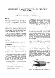
Abstract<br />
Mobile Switching Centers (MSCs) are the heart of a GSM<br />
network. Since MSC is a distributed system, it consists of<br />
different modules. Internal parts of each module can<br />
communicate which each other using HDLC protocol<br />
controller, but its speed isn’t enough for the<br />
communication between main modules, so a high-speed<br />
Embedded Local Area Network (<strong>LAN</strong>) can be a good<br />
idea for connecting these subsystems.<br />
Design of this Embedded <strong>LAN</strong> must be according to<br />
MSC’s features as a telecommunication system. So we<br />
need a network that can transfer data and information<br />
with less delay and without any error.<br />
In this paper after designing a suitable network according<br />
to a telecommunication system’s properties and<br />
simulating real conditions, some important parameters<br />
such as throughput, average delay and packet loss rate<br />
have been measured.<br />
Key Words<br />
Embedded <strong>LAN</strong> Network Performance Throughput<br />
Delay Packet Loss<br />
1. Introduction<br />
One key problem for MSC implementation as a modular<br />
system is creation the ability to transmit data and<br />
information between its subsystems with required<br />
features. In many of previous methods the control of<br />
exchanging messages between subsystems was Message<br />
Buffer’s task which its recent replacement is high speed<br />
<strong>LAN</strong>. In this paper the details of Embedded <strong>LAN</strong><br />
implementation in MSC as a telecom system and its<br />
performance related graphs have been presented.<br />
2. Embedded <strong>LAN</strong> in MSC<br />
MSC provides the services a person can request by using<br />
a mobile phone and manages the communication between<br />
GSM users and other telecommunication networks. MSC<br />
is a distributed system consisting different modules that<br />
each one has a special part of MSC’s duties. In this way<br />
each module can doing its task while is connected to other<br />
modules and can receive its required information from the<br />
others.<br />
2.1. MSC’s main parts<br />
- Digital Trunk Module (DTM):<br />
DTM’s task is signaling handover between CAS-3bit and<br />
SS7. Each DTM consists 8 DT boards with 4 E1 input<br />
lines for every one. Each DT board has two 4 Mbps lines<br />
in its output that are connected to a duplicated switch. So<br />
this switch has sixteen 4 Mbps lines in its output.<br />
- Echo Canceller (ECM):<br />
Task of this module is omitting undesirable echo related<br />
to connecting mobile and PSTN networks.<br />
- Switch:<br />
With 1024 PCM lines in the network that every 32 of<br />
them are supported with one DTM, we should have 32<br />
DTM units. Total output of this units are 512*4Mbps<br />
lines. So that we need a 64*64 central switch for<br />
switching this lines.<br />
- VLR:<br />
This unit is a database of users in the same MSC region.<br />
- Data Base:<br />
Information related to charging, routing, system<br />
management, etc are registered in this unit.<br />
2.2. Specifications of MSC’s Embedded <strong>LAN</strong><br />
We should have two computer networks for total<br />
communication in MSC: HDLC network (with low speed)<br />
for connecting internal parts of each module, and <strong>LAN</strong> for<br />
connecting main modules. Adjustment of this <strong>LAN</strong> with<br />
specifications of MSC as a telecommunication system is<br />
so important. Some of these specifications are number of<br />
users, speed, traffic rate, reliability, etc.<br />
MSC’s <strong>LAN</strong> is selected from 100Base-T type because of<br />
its high speed, low cost and wide domain of contained<br />
protocols. This network has two types of traffic: one is<br />
related to signaling packets transferred for establishment<br />
and release a conversation because mobility of<br />
subscribers, and another one refers to management<br />
packets. It means that most of the traffic is related to<br />
transfer information produced during different stages of<br />
conversation’s establishment and management. So with<br />
selecting client-server model, the only task of server will<br />
be packet handling between sender and receiver, such as a<br />
simple switch. In these conditions peer-to-peer model is<br />
more suitable. Selected protocol is TCP/IP. The main<br />
reason of this selection despite of that IPX/SPX protocol<br />
is faster and more suitable for networks with small<br />
diameter, is using Linux operating system which only<br />
supports TCP/IP. Since MSC is a real-time system any
interrupt in access of its modules to network is not<br />
permitted. So we shall not be heedless to any error such as<br />
cable breaking, NIC or hub/switch fault, etc. One solution<br />
for this can be duplicated <strong>LAN</strong>. In this case every module<br />
has two NICs with two different IP addresses, so if every<br />
module couldn’t access to the first <strong>LAN</strong> it will try through<br />
the second one.<br />
-VLR<br />
The table seen below shows the rate of VLR transactions<br />
in different routes:<br />
Route Request Response<br />
2.3. Design of duplicated <strong>LAN</strong><br />
Linux can define different routes for access to a special<br />
host in a local network using “route” instruction. Since<br />
these routes can be different in their sources, we can have<br />
routes to <strong>LAN</strong> two different with two IP address as<br />
different sources for each module using “route”<br />
instruction. Therefore if a module couldn’t send its packet<br />
through <strong>LAN</strong> over its first IP, then it will resend it over its<br />
second IP. But it is possible that a problem any where of<br />
the route to destination module’s first NIC has been<br />
error’s source. So we have assigned a unique name to<br />
each module. Source module before starting to send<br />
process, calls gethostbyname() function with destination<br />
name and externs both two IP address of destination<br />
module. So if it didn’t receive any acknowledge from<br />
destination it will resend packet to the second IP of<br />
destination module. In this way network modules don’t<br />
need to a table of others’ two IPs which should be<br />
updated periodically that will increase network’s traffic.<br />
2.4. Network performance<br />
The next step is measuring of implemented <strong>LAN</strong>’s<br />
performance in simulated real environment. Network’s<br />
bandwidth, delay and packet loss rate which are the main<br />
parameters indicating performance of a network will be<br />
worthy if offered load is equal to real traffic.<br />
2.4.1. MSC network traffic<br />
-DTM<br />
In Embedded <strong>LAN</strong> of MSC there are several types of<br />
users. For example 32 units of them are DTMs which<br />
each one supports 960 channels. According to ITU-T,<br />
every channel on 0.7 hour is busy, and if each<br />
conversation takes 1.2 minutes, so every channel will<br />
have 35 conversations per hour. Therefore we have<br />
960*35 equal to 33600 conversations per hour or 9.33 per<br />
second. Average rate of transmitted packets for every<br />
conversation is 31.5 which half of it is related to one side<br />
of conversation (caller or called), so that with assuming<br />
200 bytes as the length of a packet, the traffic related to a<br />
DTM is equal to 9.33*(35/2)*200*8 = 0.2352 Mbps and<br />
the total traffic of DTMs is 7.5264 Mbps.<br />
-Central Switches<br />
Central switches are another type of users that load two<br />
times of DTMs traffic equal to 15.0528 Mbps to the<br />
network, because they transfer two packets for every sent<br />
or received packet with a DTM.<br />
Mobile to Mobile (caller) 5 7<br />
Mobile to Mobile (called) 6 4<br />
PSTN to Mobile 5 4<br />
Mobile to PSTN 5 4<br />
Average 21/4 19/4<br />
Each DTM has 9.33 conversation/sec, so the rate of<br />
conversations for 32 DTM is about 300 conversation/sec.<br />
Therefore the traffic load of every VLR is:<br />
300(21/4 + 19/4)*200*8 = 4.8 Mbps<br />
-Data Base<br />
Most of Dbase’s load is related to charging records<br />
saving, equal to 300*1*200*8 = 0.48 Mbps.<br />
Since some protocols such as IMSI Attach, IMSI Detach,<br />
Location Updating, etc have been ignored a coefficient<br />
equal to 1.5 is assumed in total traffic accounts, so total<br />
traffic rate of MSC’s Embedded <strong>LAN</strong> is equal to<br />
1.5(7.5264 + 15.0528 + 4.8 + 0.48) = 41.7888 Mbps<br />
2.4.2. Simulated Embedded <strong>LAN</strong><br />
Simulating of Embedded <strong>LAN</strong> in real conditions and<br />
performance measurement’s conclusions have been<br />
abstracted in following graphs:<br />
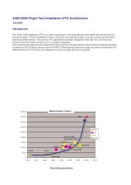
Graph (a) shows that for packets with 200 bytes length the<br />
maximum throughput is about 70 Mbps, and for offered<br />
loads less than 55 Mbps throughput graph is liner. So for<br />
41 Mbps offered load throughput of MSC’s Embedded<br />
<strong>LAN</strong> is near to 41 Mbps.<br />
In graph (b) we can see that the average delay for data<br />
transmitting nearly is 5µs.<br />
From graph (c) we can be sure that the rate of packet loss<br />
for 200 bytes as packet length is near to zero.
3. Conclusion<br />
The most important point in presented graphs is that if<br />
traffic rate of MSC’s Embedded <strong>LAN</strong> increases up to 65<br />
Mbps, throughput will remain at 100%, delay will be only<br />
10µs, and packet loss rate will be less than 0.1%. So we<br />
can be sure that despite of network traffic rate’s<br />
enhancement up to 1.5 times of current rate, MSC’s<br />
Embedded <strong>LAN</strong> will be reliable.<br />
Figure (a): Throughput versus offered load<br />
References<br />
[1]: D. LeBlanc, Linux Install and Configuratio<br />
(Coriolis Open Press, 2000).<br />
[2]: M. Mitchell, J. Oldman, Advanced Linux<br />
Programming (New Riders Publishing, 2001).<br />
[3]: G. Keiser, Local Area Network (McGraw – Hill<br />
Higher Education, 2002).<br />
[4]: K. Kummerle, Advanced in Local Area<br />
Networks (IEEE Press 1987 Editorial Board,<br />
1987).<br />
Figure (b): Mean network delay versus throughput<br />
Figure (c): Packet loss rate versus offered load