INFORMATION: Product.pdf - Iskraemeco
INFORMATION: Product.pdf - Iskraemeco
INFORMATION: Product.pdf - Iskraemeco

Create successful ePaper yourself
Turn your PDF publications into a flip-book with our unique Google optimized e-Paper software.
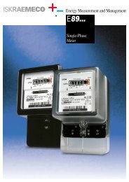
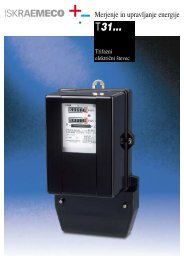
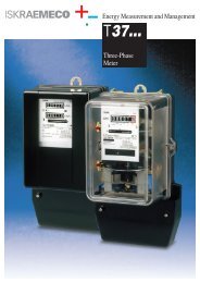
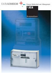
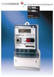
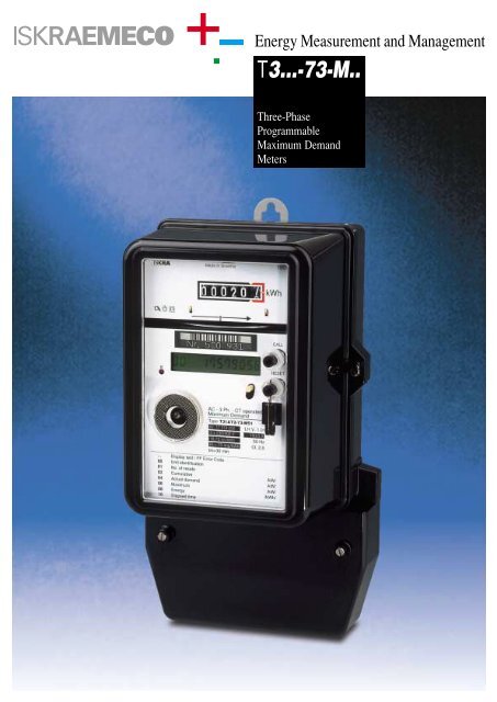
Energy Measurement and Management<br />
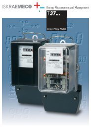
T3...-73-M..<br />
Three-Phase<br />
Programmable<br />
Maximum Demand<br />
Meters
T3...-73-M..<br />
APPLICATION<br />
The three-phase three-element active energy meter with programmable<br />
electronic maximum demand indicator (MDI) is designed for<br />
measurement and registration of electric energy and power to single<br />
or double-tariff registers. It is used for direct connection or via measuring<br />
transformers to three-phase four-wire system with balanced<br />
and unbalanced load.<br />
It is suitable for direct reading or reading with using multiplying factors.<br />
All the data can be read-out visually, or automatically by means of<br />
HHU-Hand Held Unit or PC with corresponding programme software.<br />
RATINGS<br />
The measuring and technical qualities of the meter T3.. comply with<br />
the following International Electrotechnical Commission Publications<br />
(EN 60 521, IEC 521) and Germany Standard (VDE 0418). The MDI<br />
electro-technical qualities comply with IEC 211, IEC 1036. Their construction<br />
and mechanical dimensions comply with DIN 43857 and all<br />
respective DIN dimensional standards.<br />
The accuracy class is 2. The meters connected via instrument transformers<br />
can be also class 1.<br />
GENERAL CHARACTERISTICS:<br />
The meter is an electromechanical type, with incorporated electronic<br />
microprocessor - based, programmable MDI. It is designed as simply<br />
replaceable module which enables the access to testing and calibration<br />
spots of induction measuring system. The meter measuring system<br />
is provided with mechanical parts for fixing of MDI, a special version<br />
of the rotor with markers for detection of revolutions, and voltage<br />
electromagnets with additional winding for MDI power supply.<br />
Basic functions of meter:<br />
– measurement and registration of electric energy<br />
– measurement and registration of max. average demand<br />
– registration of previous maximums<br />
– registration of cumulative maximums<br />
– indication of function errors<br />
Display – 12 digit LCD - with back light<br />
Keyboard (Push-buttons)<br />
– CALL key button (call-up sequence of the meter display)<br />
– RESET key button (resetting of MDI into<br />
initial position represents the end of<br />
billing period)<br />
Communication port<br />
Optical port for meter reading, using<br />
magnetically attached optical head.<br />
Automatic read-out is performed in<br />
compliance with IEC 1107 recommendation,<br />
“Data exchange for meter-reading,<br />
tariff and load control. Direct local<br />
data exchange."<br />
Data transmission is performed via<br />
two-directional IR optical interface,<br />
which corresponds to C mode. Protection<br />
of total data block complies<br />
with DIN 66219 standard.<br />
OPTIONS!<br />
Inputs – Inputs for tariff control<br />
and reset (external)<br />
Outputs – Pulse transmitter output<br />
– Signal output for<br />
measuring period<br />
termination<br />
CS interface – For be-directional<br />
communication<br />
1<br />
6<br />
2<br />
3<br />
5<br />
T31ATP2-73-M51<br />
METER TYPE DESIGNATION<br />
T – three-phase three-element meter<br />
31– model number (up to 60 A)<br />
37– model number (up to 100 A)<br />
A – 120 or 200-percent overload<br />
B – 300-percent overload<br />
C – 400-percent overload<br />
E – 500-percent overload<br />
F<br />
– 600-percent overload<br />
– (blank) direct connection<br />
T – connection via instrument transformers<br />
– (blank) accuracy class 2<br />
P – accuracy class 1<br />
– (blank) two-cup, ball lower bearing<br />
2 – magnetic lower bearing<br />
73– Electronic tariff device<br />
M – registers for energy and power<br />
5 – single-rate version<br />
6 – double-rate version<br />
1 – without pulse transmitter<br />
2 – with pulse transmitter<br />
DEVICE APPEARANCE<br />
4<br />
7<br />
8<br />
9<br />
10<br />
1 –Mechanical register<br />
2 –Meter test LED<br />
3 –R communication port<br />
4 –12-digit LCD<br />
5 –Meter technical data<br />
6 –Bar code<br />
7 –Scroll push-button<br />
8 –Reset push-button<br />
9 –Sealing attachment of<br />
reset push-button<br />
10–List of data identification<br />
codes
T3...-73-M..<br />
DATA DISPLAY<br />
Data on numerical 12-digit display<br />
are displayed cyclically. A data<br />
identification and data in register<br />
are displayed on the LCD.<br />
08 00002.6<br />
Data in register<br />
Data identification<br />
Every ten seconds data, shown<br />
in table 4.1., are displayed. The<br />
display is not illuminated.<br />
When a key (Call) for manual<br />
data read-out is pressed, the<br />
display is illuminated for 3 minutes.<br />
Every ten seconds data<br />
are displayed cyclically as<br />
shown in table 1. When a key is<br />
pressed the second time, data<br />
stated in table 4.2. are displayed<br />
then. If you want certain<br />
data are to be shown, the CALL<br />
key should be pressed successively<br />
until desired data are displayed<br />
on the LCD.<br />
Previous monthly values are stated<br />
for the case of 15 stored<br />
billing periods. In the table RR-1<br />
or RR-15 the data value under<br />
the data identification 01 is<br />
decreased for 1 or 15.<br />
Programming:<br />
The meter MDI module is programmable<br />
and programming<br />
method depends on the MDI<br />
module equipment. With maximal<br />
equipped plate the device can<br />
be set manually or over IR optical<br />
interface with HHU or PC<br />
and with corresponding programme<br />
software. Programmable<br />
options are shown in table 4.2.<br />
stated at D.I. 90 up to 95.<br />
Table 4.1.<br />
D.I. DATA DESCRIPTION<br />
02 000.000 Cumulative of maximums M1 (kW)<br />
03 000.000 Cumulative of maximums M2 (kW)<br />
04TT 0.000 Actual demand M1 (kW)<br />
05TT 0.000 Actual demand M2 (kW)<br />
06 0.000 Maximum M1 (kW)<br />
07 0.000 Maximum M2 (kW)<br />
08 * 00000.0 Energy of the 1st tariff T1 (kWh)<br />
09 * 00000.0 Energy of the 2nd tariff T2 (kWh)<br />
10 000 Number of days from the MDI reset<br />
Table 4.2.<br />
D.I. DATA DESCRIPTION<br />
00 00000000 Identification number of that meter<br />
01 RR Number of maximum demand indicator resets<br />
02 000.000 Cumulative of maximums M1 (kW)<br />
03 000.000 Cumulative of maximums M2 (kW)<br />
04TT 0.000 Actual demand M1 (kW)<br />
05TT 0.000 Actual demand M2 (kW)<br />
06 0.000 Maximum M1 (kW)<br />
06RR 0.000 Previous monthly values M1 (RR-1 to RR-15)<br />
07 0.000 Maximum M2 (kW)<br />
07RR 0.000 Previous monthly values M2 (RR-1 to RR-15)<br />
08 * 00000.0 Energy of the 1st tariff T1 (kWh)<br />
08RR 00000.0 Energy of previous values T1 (RR-1 to RR-15)<br />
09 * 00000.0 Energy of the 2nd tariff T2 (kWh)<br />
09RR 00000.0 Energy of previous values T2 (RR-1 to RR-15)<br />
10 000 Number of days from the MDI reset<br />
90 1 Display energy activated 1 / not activated 0<br />
91 0000.E0 Format of MDI constant<br />
92 0500 Constant of MDI<br />
93 10 Ratio demand / energy (10 or 100)<br />
94 5 Measuring period Tm (60, 30, 20, 15, 12, 10, 6, 5)<br />
95 0 Tm in % or minutes (0 - %, 1 - min.)<br />
FF 00 Diagnostic error<br />
FF10 00 Failure voltage indicator<br />
* The registers are displayed only if the register 90 is activated.<br />
D.I. Data identification<br />
RR Number of resets<br />
TT Percentage of measuring period<br />
TECHNICAL DATA<br />
Rated voltage (Un) . . . . . . . . . . . . . . . . . . . .3 x 230/400 V<br />
or 3 x 110/√3 / 110 V or ...<br />
Frequency . . . . . . . . . . . . . . . . . . . . . . . . . . . . . .50 Hz<br />
Rated current . . . . . . . . . . . . . . . . . . . . . .5 A (10 A, 20 A,...)<br />
Maximum current . . . . . . . . . . . . . . . . . . .6 A (60 A, 100 A,...)<br />
Torque (x10 -4 Nm) . . . . . . . . . . . . . . . . . . . . .approx. 6 –10<br />
Starting current . . . . . . . . . . . . . . . . . . . . .0.5 % Ib at U.P.f.<br />
Running with no load . . . . . . . . . . . . . . . .80 % to 110 % Un<br />
Temperature range . . . . . . . . . . . . . . . . . .–10 °C to + 50 °C<br />
Storage temperature . . . . . . . . . . . . . . . . .–25 °C to + 70 °C<br />
Degree of protection . . . . . . . . . . . . . . . . .IP - 51 to IEC 529<br />
Meter mass . . . . . . . . . . . . . . . . . . . . . . . .approx. 3.7 - 4.0 kg<br />
Tariff inputs<br />
(for electrical resetting of MDI module) . . . . . .230 V or 100 V, 50 Hz,<br />
Measuring period and/or pulse emitter output (Options)<br />
Mercury relay contact. . . . . . . . . . . . . . .max. 250 V AC, max. 25 VA<br />
Opto-mos contact . . . . . . . . . . . . . . . . .max. 250 V AC, max. 25 VA<br />
Optocoupler contact (S0-DIN 43864) . . . .max. 25 V DC, max. 30 mA<br />
Electromagnet compatibility<br />
Electrostatic discharges: . . . . . . . . . . . . . . . .15 kV (IEC 801-2)<br />
Electromagnetic field: . . . . . . . . . . . . . . . . .10 V/m (IEC 801-3)<br />
Burst test: . . . . . . . . . . . . . . . . . . . . . . . . .2 kV (IEC 801-4)<br />
Dielectric strength: . . . . . . . . . . . . . . . . . . .2 kV, 50 Hz, 1 min.<br />
Impulse voltage withstand: . . . . . . . . . . . . . . .6 kV (1.2/50 µs)
T3...-73-M..<br />
CONNECTION DIAGRAMS<br />
T31 -- -73-M51<br />
T31 - T - -73-M51<br />
T31 - T - -73-M61<br />
MDI<br />
MDI<br />
T1/2<br />
T1/2<br />
MR<br />
L1<br />
L2<br />
L3<br />
N<br />
1<br />
3 4 6 7 9 10 12<br />
1 2 3 4 5 6 7 8 9 11<br />
k l k l k l<br />
K L K L K L<br />
L1<br />
L2<br />
L1<br />
L2<br />
L3<br />
u u u<br />
x x x<br />
X X X<br />
U U U<br />
1 2 3 4 5 6 7 8 9 11<br />
k l k l k l<br />
K L K L K L<br />
13<br />
14 15 18 19<br />
T1/2 Change-over for energy<br />
M1/2 Change-over for maximum<br />
MR External reset into initial state<br />
OVERALL AND FIXING DIMENSIONS<br />
CONNECTION VIA<br />
MEASURING<br />
TRANSFORMERS<br />
DIRECT CONNECTION<br />
up to 60 A<br />
DIRECT CONNECTION<br />
up to 100 A<br />
Owing to periodical improvements of our products the supplied products can differ in<br />
some details from the data stated in the prospectus material.<br />
722.999.130 9811/56<br />
<strong>Iskraemeco</strong>, Energy Measurement and Management<br />
4000 Kranj, Savska loka 4, Slovenia<br />
Telephone: (+386 4) 206 40 00, Telefax: (+386 4) 206 43 76, http://www.iskraemeco.si, e-mail: info@iskraemeco.si<br />
Published by <strong>Iskraemeco</strong>. Data subject to alteration without notice.