E7_E8_prospect.pdf - Iskraemeco
E7_E8_prospect.pdf - Iskraemeco
E7_E8_prospect.pdf - Iskraemeco

Create successful ePaper yourself
Turn your PDF publications into a flip-book with our unique Google optimized e-Paper software.
<strong>E7</strong>2..-01<br />
PULSE TRANSMITTER (<strong>E7</strong>... -5 and <strong>E7</strong>... -9 )<br />
PURPOSE AND APPLICATION:<br />
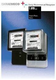
Pulse transmitters (series -5 and series -9 ) can be built into single-phase electricity meters, accuracy class 2. They are used for<br />
generating and transmitting pulses to tariff devices, for summing up, inspecting, recording as well as data processing, for<br />
reasonable consuming and billing electric energy. Pulse frequency is proportional to meter rotor speed as well as to electric<br />
energy consumption.<br />
Transmission of pulses from the meter to the central unit is performed through special two-wire lines.<br />
STANDARDS : Pulse transmitters are made in compliance with DIN 43 864 standard and IEC 1036, Articles 5.5.2. to 5.5.5.;.<br />
TECHNICAL DATA <strong>E7</strong>2... -5<br />
SO (DIN 43 864) pulse output type<br />
Power supply voltage . . . . . . . . . . . .Un = 24 (+3, –6) V<br />
Voltage on terminals - active state<br />
. . .Usa < 8 V<br />
Resistance in external circuit . . . . . . . .Rb = 1 kΩ<br />
Transmitter current - active state . . . . .10 mA < Ia < 20 mA<br />
Transmitter current - inactive state . . . .Ip < 2 mA<br />
No. of pulses<br />
. . . . . . . . . . . . . . . . .1 or 2 imp./rev.<br />
Min. pulse length . . . . . . . . . . . . . . .30 ms<br />
Reverse stop . . . . . . . . . . . . . . . . . .2 or 4-part<br />
Operating temperature range . . . . . . . .–20 °C to +60 °C<br />
Pulse transmission length . . . . . . . . .0.5 m<br />
TECHNICAL DATA <strong>E7</strong>2.. -9<br />
There are two types of pulse transmitters:<br />
a.) Optoisolated transistor pulse output SO (DIN 43 864)<br />
Power supply voltage . . . . . . . . . . . .Un = 24 (+3, –6) V<br />
b.) Relay output : (Output switch)<br />
max. power . . . . . . . . . . . . . . .25 VA<br />
Voltage on terminals - active state . . .Usa < 6 V max. voltage . . . . . . . . . . . . .250 V AC / DC<br />
Resistance in external circuit . . . . . . . .Rb = 1 kΩ<br />
Transmitter current - active state . . . . .5 mA < Ia < 20 mA<br />
max. current . . . . . . . . . . . . . .0,5 A<br />
contact bounce . . . . . . . . . . . .no<br />
Transmitter current - inactive state . . . .Ip < 0,25 mA Self-consumption . . . . . . . . . .0,3 VA<br />
No. of pulses . . . . . . . . . . . . . . . . .1 or 2 imp./rev. No. of pulses . . . . . . . . . . . . .1 or 2 imp./rev.<br />
Output pulse length . . . . . . . . . . . . . .80 ms ±15 % Output pulse length . . . . . . . . .80 ms ±15 %<br />
Reverse stop . . . . . . . . . . . . . . . . . .2 or 4-part<br />
Mechanical reverse stop: . . . . . .2 or 4-part<br />
Operating temperature range: . . . . . . .–20 °C to +60 °C Operating temperature range . . .–20 °C to +60 °C<br />
Pulse transmission length . . . . . . . . .0,5 m<br />
Pulse transmission length . . . . .to 2000 m