E7_E8_prospect.pdf - Iskraemeco
E7_E8_prospect.pdf - Iskraemeco
E7_E8_prospect.pdf - Iskraemeco

Create successful ePaper yourself
Turn your PDF publications into a flip-book with our unique Google optimized e-Paper software.
<strong>E7</strong>2..-01<br />
Both voltage and current coils<br />
can easily be replaced.<br />
Electromagnetic sheets of a corresponding<br />
initial permeability in<br />
current cores assures specified<br />
error curves with respect to the<br />
load, either at small loads or<br />
overloads. Electromagnetic sheet<br />
metal for laminations of voltage<br />
and current cores as well as for<br />
other parts has been previously<br />
selected by uniform electric<br />
magnetic characteristics.<br />
A special combination of the<br />
stray current connection and<br />
previous magnetisation of current<br />
core with voltage magnetic<br />
flux, enables high accuracy of a<br />
whole wide load range.<br />
Bearings<br />
Upper bearing is a pin type and<br />
serves as an axial rotor guide. A<br />
pin made of stainless steel<br />
spindle smoothly slides in the<br />
sintered graphite bearing. The<br />
pin is pressed into the brass<br />
sleeve. A sleeve with the pin is<br />
fastened to the meter frame. The<br />
bearing has exceptionally small<br />
and time constant friction and<br />
should not be lubricated.<br />
Lower bearing is of two cup or<br />
magnetic type.<br />
The two-cup bearing<br />
A highly polished steel ball,<br />
greased with high-quality oil<br />
against corrosion, lies<br />
between two sapphire cups.<br />
The bearing features minimum<br />
start friction and considerably<br />
long life. The bearing insert is<br />
elastically located to prevent<br />
damage during transportation<br />
and to enable easy replacement<br />
by pressing the bearing<br />
insert, without need of readjustment<br />
of the bearing height.<br />
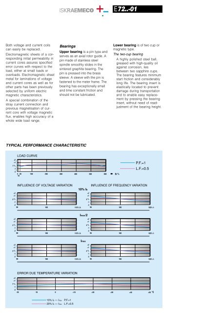
TYPICAL PERFORMANCE CHARACTERISTIC<br />
LOAD CURVE<br />
+2<br />
+1<br />
F %<br />
-1<br />
-2<br />
5 20 100 200 300 400 500 600 Ib %<br />
10<br />
P.F.=1<br />
L.F.=0.5<br />
INFLUENCE OF VOLTAGE VARIATION<br />
+2<br />
+1<br />
p %<br />
-1<br />
-2<br />
90 100 110% Ur<br />
10% Ib<br />
INFLUENCE OF FREQUENCY VARIATION<br />
+2<br />
+1<br />
p %<br />
-1<br />
-2<br />
95 100 105% fr<br />
+2<br />
+1<br />
p %<br />
-1<br />
-2<br />
90 100 110% Ur<br />
Imax/2<br />
+2<br />
+1<br />
p %<br />
-1<br />
-2<br />
95 100 105% fr<br />
+2<br />
+1<br />
p %<br />
-1<br />
-2<br />
90 100 110% Ur<br />
Imax<br />
+2<br />
+1<br />
p %<br />
-1<br />
-2<br />
95 100 105% fr<br />
ERROR DUE TEMPERATURE VARIATION<br />
+2<br />
+1<br />
F %<br />
-1<br />
-2<br />
-20<br />
-10 0 +10 +20 +30 +40 +50 °C<br />
10% Ib — Imax P.F.=1<br />
20% Ib — Imax L.F.=0.5