I-556 Fin Tube Duct Heater Installation, Operation and ... - Brasch
I-556 Fin Tube Duct Heater Installation, Operation and ... - Brasch I-556 Fin Tube Duct Heater Installation, Operation and ... - Brasch
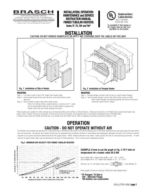
INSTALLATION, OPERATION MAINTENANCE and SERVICE INSTRUCTION MANUAL FINNED TUBULAR HEATERS Series TF, TS, TAF and TW* DUCT HEATER ISSUE NO. XXX To establish if this heater is UL Listed, look for this Listing Mark on the heater. INSTALLATION CAUTION: DO NOT REMOVE NAMEPLATE OR APPLY ANY COVERING OVER THE LABELS ON THIS UNIT. Fig. 1 Installation of Slip in Heater MOUNTING Step 1 - Cut hole in side of duct 1/8" larger than heater body. Step 2 - Insert heater body all the way into duct until terminal box covers opening. Step 3 - Secure heater in place with sheet metal screws. Note: For vertical airflow, angle brackets, a maximum of 1" wide, are recommended inside the duct on both sides to support the heater when the duct width exceeds 24 inches. Fig. 2 Installation of Flanged Heater MOUNTING Step 1 - Provide flanges on both ends of duct to match heater flanges. Step 2 - Secure heater flanges to duct with sheet metal screws or bolts. Note: When flanges are aligned properly, the entire coil section should be within the air stream. These heaters are suitable for either vertical up or horizontal airflow with airflow in either direction. Observe instructions on UP label when positioning heater (see Page 2, Item 7) Note: If mercury contactors or SCRs are built into the heater, it will operate only in the position indicated by the CAUTION label. In special cases where the heater terminal box is no longer than the heater frame, refer to separate mounting instructions, Bulletin I-139. For efficient and trouble-free operation it is important that air distribution be uniform over all the heating coils in the entire heated section and particularly the area where the coils terminate. No electric duct heater should ever be operated with insufficient airflow or overheating and subsequent damage will result. The minimum velocity required at any point should be determined from the graph below. NOTE: Heating elements may retain a light surface film die to manufacturing processes. A small amount of vapor and/or odor may be detected at the start of initial operation. This is normal and completely harmless. Fig.3 MINIMUM AIR VELOCITY FOR FINNED TUBULAR HEATERS OPERATION CAUTION - DO NOT OPERATE WITHOUT AIR EXAMPLE of how to use the graph in Fig. 3 75°F inlet air temperature for a heater rated 20.0 KW. Duct width (W) = (open face width = 24" - ¾" = 23¼") Duct height (H) = 12" (open face height = 12" - 3" = 9") 20.0 KW per sq. ft. of heater face area = (9) (23¼) = 13.8 KW/Sq. Ft. 144 From graph minimum velocity is 855 fpm (see dotted lines). *TF-Flanged, TS-Slip-in TAF - Alternate Flange TW-Outdoor use construction BULLETIN I-556 / page 1
- Page 2 and 3: HOW NOT TO INSTALL DUCT HEATERS Ele
- Page 4: WIRING INSTRUCTIONS DISCONNECT ALL
INSTALLATION, OPERATION<br />
MAINTENANCE <strong>and</strong> SERVICE<br />
INSTRUCTION MANUAL<br />
FINNED TUBULAR HEATERS<br />
Series TF, TS, TAF <strong>and</strong> TW*<br />
DUCT HEATER<br />
ISSUE NO. XXX<br />
To establish if this heater is<br />
UL Listed, look for this Listing<br />
Mark on the heater.<br />
INSTALLATION<br />
CAUTION: DO NOT REMOVE NAMEPLATE OR APPLY ANY COVERING OVER THE LABELS ON THIS UNIT.<br />
Fig. 1 <strong>Installation</strong> of Slip in <strong>Heater</strong><br />
MOUNTING<br />
Step 1 - Cut hole in side of duct 1/8" larger than heater body.<br />
Step 2 - Insert heater body all the way into duct until terminal box covers<br />
opening.<br />
Step 3 - Secure heater in place with sheet metal screws.<br />
Note: For vertical airflow, angle brackets, a maximum of 1" wide,<br />
are recommended inside the duct on both sides to support the<br />
heater when the duct width exceeds 24 inches.<br />
Fig. 2 <strong>Installation</strong> of Flanged <strong>Heater</strong><br />
MOUNTING<br />
Step 1 - Provide flanges on both ends of duct to match heater flanges.<br />
Step 2 - Secure heater flanges to duct with sheet metal screws or bolts.<br />
Note: When flanges are aligned properly, the entire coil section<br />
should be within the air stream.<br />
These heaters are suitable for either vertical up or horizontal airflow with airflow in either direction. Observe instructions on UP label when positioning heater (see<br />
Page 2, Item 7) Note: If mercury contactors or SCRs are built into the heater, it will operate only in the position indicated by the CAUTION label.<br />
In special cases where the heater terminal box is no longer than the heater frame, refer to separate mounting instructions, Bulletin I-139.<br />
For efficient <strong>and</strong> trouble-free operation it is important that air distribution be uniform over all the heating coils in the entire heated section <strong>and</strong> particularly the area where<br />
the coils terminate. No electric duct heater should ever be operated with insufficient airflow or overheating <strong>and</strong> subsequent damage will result. The minimum velocity<br />
required at any point should be determined from the graph below. NOTE: Heating elements may retain a light surface film die to manufacturing processes. A small<br />
amount of vapor <strong>and</strong>/or odor may be detected at the start of initial operation. This is normal <strong>and</strong> completely harmless.<br />
Fig.3 MINIMUM AIR VELOCITY FOR FINNED TUBULAR HEATERS<br />
OPERATION<br />
CAUTION - DO NOT OPERATE WITHOUT AIR<br />
EXAMPLE of how to use the graph in Fig. 3 75°F inlet air<br />
temperature for a heater rated 20.0 KW.<br />
<strong>Duct</strong> width (W) = (open face width = 24" - ¾" = 23¼")<br />
<strong>Duct</strong> height (H) = 12" (open face height = 12" - 3" = 9")<br />
20.0<br />
KW per sq. ft. of heater face area = (9) (23¼) = 13.8 KW/Sq. Ft.<br />
144<br />
From graph minimum velocity is 855 fpm (see dotted lines).<br />
*TF-Flanged, TS-Slip-in<br />
TAF - Alternate Flange<br />
TW-Outdoor use construction<br />
BULLETIN I-<strong>556</strong> / page 1
HOW NOT TO INSTALL DUCT HEATERS<br />
Electric duct heaters differ from other types of heating coils (such as steam or hot water coils) in that they produce<br />
100% heat as long as the elements are energized, regardless of air flow. Therefore, problems may arise if portions of<br />
the heater are blocked. Listed below are some of the important items to watch when installing any duct heater.<br />
1<br />
2<br />
3<br />
4<br />
5<br />
6<br />
7<br />
8<br />
DO NOT OPERATE WITHOUT AIR<br />
<strong>Heater</strong> should be interlocked with fan (using pressure<br />
type airflow switch or electrical interlock). Do not<br />
energize heaters with remote contactors until thermal<br />
cutout has been connected.<br />
DO NOT OPERATE HEATER WITH INADE-<br />
QUATE AIRFLOW<br />
Refer to Figure 3, Page 1 to obtain minimum velocity<br />
needed to keep heating coils from glowing red <strong>and</strong> to<br />
prevent nuisance tripping of thermal cutout.<br />
DO NOT OPERATE HEATER WITH UNEVEN<br />
AIR DISTRIBUTION<br />
Adequate airflow must be present at all points of the<br />
heater face area. Use of turning vanes or baffles may<br />
be necessary to obtain even air distribution.<br />
AIR MUST BE FILTERED <strong>and</strong> free of combustible<br />
particles <strong>and</strong> hazardous vapors.<br />
LEAVE AT LEAST 48” BETWEEN DUCT<br />
HEATER AND ANY TURN OR ELBOW in<br />
the ductwork <strong>and</strong> between heater <strong>and</strong> heat pumps or<br />
air conditioners. If less than 48" between heater <strong>and</strong><br />
elbow, provide turning vanes <strong>and</strong> order heater with<br />
coils derated to 35W/in 2 . Absolute minimum between<br />
heater <strong>and</strong> elbow is 24".<br />
LEAVE AT LEAST 48” BETWEEN HEATER<br />
AND DUCT TRANSITION. Transitions can be<br />
avoided by specifying a duct heater sized to match the<br />
duct size exactly. If a transition cannot be avoided <strong>and</strong><br />
heater has to be less than 48" from the transition,<br />
transition should conform to the maximum angles<br />
indicated at right.<br />
DO NOT MOUNT HEATER WITH TERMINAL<br />
BOX ON TOP OR BOTTOM OF HORIZONTAL<br />
DUCT because safety devices will be in wrong<br />
positions to ensure proper operation. For applications<br />
where electrical connections must be at bottom,<br />
specify UL Listed open coil bottom insert heater (slip-in)<br />
or flanged heater with UL Listed bottom outlet box.<br />
DO NOT INSTALL HEATER IN HORIZONTAL<br />
DUCT WITH THERMAL CUTOUT AT BOTTOM<br />
heaters can be mounted in any position in a vertical or<br />
horizontal duct except when mounted in a horizontal<br />
duct the thermal cutout must be at the top. Follow<br />
THIS SIDE UP instructions on heater.<br />
NOTE: If mercury contactors or SCRs are built into the<br />
heater, install only in the position indicated by the<br />
CAUTION label.<br />
Example: 20 KW <strong>Heater</strong> W = 24 = 12<br />
Minimum velocity required<br />
is 885 fpm (see Fig. 3, Page 1).<br />
885 fpm<br />
250 fpm<br />
700 fpm<br />
450 fpm<br />
BULLETIN I-<strong>556</strong> / page 2
9<br />
10<br />
11<br />
DO NOT INSTALL STANDARD HEATER IN<br />
DUCTS WITH INTERNAL INSULATION<br />
because the obstruction may block airflow near coil<br />
terminations, cutout <strong>and</strong> heat limiters. Instead, use a<br />
special slip-in heater with recessed terminal box <strong>and</strong><br />
reduce frame size or a flanged heater with face area<br />
equal to inside duct dimensions <strong>and</strong> extra wide flanges.<br />
NOTE:<br />
For heaters used in air conditioning ducts in<br />
areas of high relative humidity, specify insulated<br />
terminal box to prevent condensation.<br />
DO NOT INSULATE EXTERIOR OF TERMINAL<br />
BOX.<br />
Terminal box must not be externally insulated or<br />
blocked in any way. Use heaters with factory-installed<br />
insulation on duct side of terminal box.<br />
DO NOT INSTALL STANDARD HEATER where<br />
face area may be blocked by frame members, filters,<br />
filter supports, insulation cooling coil headers, blower<br />
scrolls or any other kind of obstruction. Use recessed<br />
terminal box <strong>and</strong> order heater with no coils three to<br />
four inches from top, bottom or back flange.<br />
HORIZONTAL DUCT (TOP VIEW CUTAWAY)<br />
12<br />
13<br />
14<br />
15<br />
16<br />
NOTE:<br />
Derating of coils is no substitute for good air<br />
distribution. Therefore, heater should be<br />
located as far as possible from obstructions<br />
in airstream.<br />
DO NOT INSTALL HEATER NEAR DUAL<br />
OUTLET BLOWER since there will be little or no<br />
airflow across area between dual outlets. Use individual<br />
heaters for each blower outlet or move heater far<br />
enough (four feet minimum) from dual outlets to assure<br />
good air distribution. Derated elements also help to<br />
assure trouble-free operation under these conditions.<br />
HEATER IN SERIES - Two heaters can be installed<br />
in series proving:<br />
a) the leaving air temperature of the first heater<br />
does not exceed 100ºF<br />
b) both heaters have a minimum air velocity<br />
according to the graph, Figure 3, Page 1, <strong>and</strong><br />
c) the downstream heater is a Type TS or TF <strong>and</strong> so located that it will not "see" the upstream heater; thus, the<br />
upstream heater can be in the main duct <strong>and</strong> the downstream heater can be in a branch duct. Where both<br />
heaters are in the same duct, a minimum distance of five feet between heaters is required.<br />
LONG HEATERS - It is recommended that heaters with W Dimensions greater than 72" be ordered with a linear thermal cutout.<br />
The sensing element of the linear cutout extends the entire length of the heater <strong>and</strong> turns the heater off when a hot spot develops.<br />
When hot spot has cooled, heater resumes normal operation.<br />
DO NOT CONNECT ALUMINUM SUPPLY WIRES to st<strong>and</strong>ard duct heater. <strong>Heater</strong> must be ordered with special line<br />
terminals suitable for aluminum conductors <strong>and</strong> sized to accept the larger gauge required.<br />
DO NOT INSTALL STANDARD HEATER OUTDOORS - if heater will be subject to weather, specify raintight construction.<br />
17<br />
DO NOT BUNDLE, TIE OR WRAP POWER WIRING IN GROUPS as this may cause overheating <strong>and</strong> eventual breakdown<br />
of insulation.<br />
BULLETIN I-<strong>556</strong> / page 3
WIRING INSTRUCTIONS<br />
DISCONNECT ALL POWER SOURCES before doing any work on the heater installation. Follow the wiring diagram located on inside of terminal box cover. If there<br />
is more than one heating step, wire the unit so the steps are energized in the same sequence as numbered in the heater. If the heater does not have a built-in<br />
disconnect switch or main circuit breaker, install a remote disconnect in accordance with the National Electric Code Articles 424-65 <strong>and</strong> 424-19. The fan must be<br />
interlocked with the heater so that the heater is not energized unless the fan is on. UL Listed heaters have a fan interlock either built-in or furnished as part of a<br />
separate UL Listed assembly. If remote contractors are employed, they must have adequate ratings <strong>and</strong> be UL Listed for 100,000 cycles of operation. Do not exceed<br />
the control circuit volt-ampere rating shown on the nameplate. These contractors must be supplied by <strong>Brasch</strong> Manufacturing Company for a UL Listed heater. Use<br />
NEC Class 1 wiring for the control circuit as described in Article 725 of the National Electrical Code. Before placing heater in operation, make sure all terminal<br />
connections are tight. It is recommended that all terminals be re-tightened after the first 24 hours of operation <strong>and</strong> checked for tightness at least once each year thereafter.<br />
MAINTENANCE<br />
<strong>Brasch</strong> heaters are made with the finest components available, tested by a trained quality control engineer <strong>and</strong> should not normally require maintenance except for<br />
periodic tightening of terminals (see Wiring). Associated equipment, however, may require periodic cleaning, adjustment or calibration. Maintenance of<br />
associated equipment should be performed in accordance with manufacturer's specifications.<br />
SERVICE INSTRUCTIONS<br />
All ELECTRODUCT heaters are equipped with double safety protection (automatic reset thermal cutout usually in the control circuit <strong>and</strong> heat limiters <strong>and</strong>/or<br />
manual reset thermal cutouts in the power lines). <strong>Heater</strong> may also have optional additional safety devices. Safety devices should not be replaced without first<br />
correcting the problem causing them to open the circuit. Additional instruction manuals covering specific components will be supplied with any built-in equipment<br />
other than the st<strong>and</strong>ard thermal cutouts. DISCONNECT ALL SOURCES OF POWER BEFORE SERVICING EQUIPMENT. Replace safety devices only with BRASCH part<br />
numbers located on labels near safety devices.<br />
On heaters having removable elements the following procedure should be used to remove <strong>and</strong> replace elements:<br />
1. Disconnect all power sources before servicing equipment. 4. Grasp element mounting nut with pliers <strong>and</strong> gently withdraw<br />
2. Remove wiring from element to be removed. element thru terminal box.<br />
3. Remove two sheet metal screws at top <strong>and</strong>bottom corners 5. To replace element, reverse order of above steps.<br />
element mounting plate.<br />
are wired per attached attached circuit diagram.<br />
LOCATING TROUBLE<br />
1<br />
2<br />
3<br />
PROBLEM<br />
HEATER<br />
WILL NOT<br />
OPERATE<br />
HEATER CYCLES<br />
(WILL NOT<br />
STAY ON)<br />
IMPROPER<br />
TEMPERATURE<br />
REGULATION<br />
POSSIBLE SOLUTION<br />
Recheck installation instructions (page 2 & 3) <strong>and</strong> wiring diagrams to be sure equipment has been installed according to<br />
manufacturer's recommendations.<br />
Disconnect switch or main circuit breaker may be in "OFF" position. If heater has built-in disconnect switch, door must<br />
be closed <strong>and</strong> switch turned ON" before heater will operate.<br />
If the fan <strong>and</strong> heater are interlocked with a fan relay, the fan must be on before the heater will operate. If an airflow switch<br />
is used, air pressure in the duct must be sufficient (at least .07" WC) to close the switch before the heater will operate.<br />
Automatic (or manual) reset thermal cutout (see Form I-12) may have opened when overheating resulted from insufficient<br />
airflow or poor air distribution. Allow heater temperature to return to normal so that automatic thermal cutout may reset<br />
or manual reset thermal cutout may be reset. Correct cause of overheating before proceeding.<br />
Heat limiter(s) may have opened if local "hot spot" developed or if automatic reset thermal cutout failed to open first,<br />
when overheating occurred. Correct cause of overheating <strong>and</strong> replace heat limiter (see Form I-12).<br />
Check main fuses. If open correct cause of failure before replacing fuses.<br />
Check air inlet <strong>and</strong> discharge openings for obstructions. See that filters are not clogged, fire dampers are open <strong>and</strong> air<br />
system is balanced.<br />
Check to see that the heater terminal box is tight against duct <strong>and</strong> heater safety devices are receiving sufficient air flow.<br />
Air flow must be distributed evenly over entire face area.<br />
Look at heater coils in operation (through observation port in duct); any red area is not receiving enough air (A small<br />
amount of redness is permissible inside the coil insulating bushings.) Refer to minimum air flow graph (Fig. 3) for air flow<br />
requirements <strong>and</strong> make sure that air flow through every part of the heater is sufficient. Coils must not glow.<br />
If air flow switch is used, contactors may "chatter" if airflow is not sufficient to keep switch fully on.<br />
If duct has internal insulation, the insulation may be blocking the safety devices (see Page 3, Item 9).<br />
Recheck installation instructions (pages 2 & 3) <strong>and</strong> wiring diagrams to be sure equipment has been installed according to<br />
manufacturer's recommendations.<br />
Make sure associated control equipment, such as thermostats, are in the correct location <strong>and</strong> that all controls are<br />
adjusted according to manufacturer's specifications for existing field conditions.<br />
Check air system balance to see that correct amount of airflow is supplied for proper zone control.<br />
Automatic thermal cutout may be opening (cycling) before room thermostat is satisfied. (See 2 above).<br />
Insufficient heat may be caused by:<br />
A. Open heat limiter(s) or thermal cutout. B. Incorrect supply voltage. C. <strong>Heater</strong> too small (in wattage)<br />
for application.<br />
BRASCH LIMITED WARRANTY<br />
<strong>Brasch</strong> Manufacturing Company, Inc. warrants heater resistance coils against defects in material <strong>and</strong> workmanship for a period of two years from the date of shipment.<br />
Other components <strong>and</strong> accessories are guaranteed, for a period of one year from date of shipment, against defects in material <strong>and</strong> workmanship. Should<br />
evidence of defects in material or workmanship occur during the warranty period, <strong>Brasch</strong> Manufacturing Company, Inc. will repair or replace the heater, at its own<br />
discretion, without charge. <strong>Brasch</strong> Manufacturing Company, Inc. shall not be held responsible for any charges in connection with the removal or replacement of<br />
allegedly defective equipment; nor for incidental or consequential damage. This warranty does not apply to damage from accident, misuse or alteration. Also,<br />
this warranty does not apply where the connected voltage is more the 5% above product nameplate voltage, nor to equipment that has been improperly installed,<br />
wired or maintained.<br />
BULLETIN I-<strong>556</strong> / page 4


