

Data Sheet PacDriveâ„¢ iSH Servo Drive System - Orbit Motion ...
Data Sheet PacDriveâ„¢ iSH Servo Drive System - Orbit Motion ...
Data Sheet PacDriveâ„¢ iSH Servo Drive System - Orbit Motion ...

You also want an ePaper? Increase the reach of your titles
YUMPU automatically turns print PDFs into web optimized ePapers that Google loves.
<strong>Data</strong> <strong>Sheet</strong><br />
Pac<strong>Drive</strong><br />
<strong>iSH</strong> <strong>Servo</strong> <strong>Drive</strong> <strong>System</strong><br />
High-dynamic AC <strong>Servo</strong> drives<br />
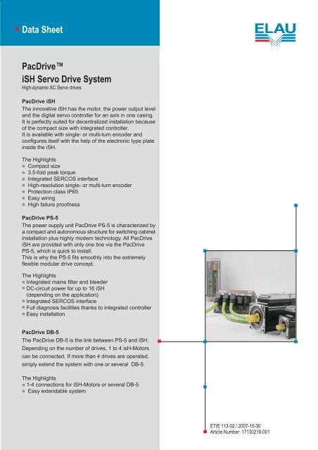
Pac<strong>Drive</strong> <strong>iSH</strong><br />
The innovative <strong>iSH</strong> has the motor, the power output level<br />
and the digital servo controller for an axis in one casing.<br />
It is perfectly suited for decentralized installation because<br />
of the compact size with integrated controller.<br />
It is available with single- or multi-turn encoder and<br />
configures itself with the help of the electronic type plate<br />
inside the <strong>iSH</strong>.<br />
The Highlights<br />
Compact size<br />
3.5-fold peak torque<br />
Integrated SERCOS interface<br />
High-resolution single- or multi-turn encoder<br />
Protection class IP65<br />
Easy wiring<br />
High failure proofness<br />
Pac<strong>Drive</strong> PS-5<br />
The power supply unit Pac<strong>Drive</strong> PS-5 is characterized by<br />
a compact and autonomous structure for switching cabinet<br />
installation plus highly modern technology. All Pac<strong>Drive</strong><br />
<strong>iSH</strong> are provided with only one line via the Pac<strong>Drive</strong><br />
PS-5, which is quick to install.<br />
This is why the PS-5 fits smoothly into the extremely<br />
flexible modular drive concept.<br />
The Highlights<br />
Integrated mains filter and bleeder<br />
DC-circuit power for up to 16 <strong>iSH</strong><br />
(depending on the application)<br />
Integrated SERCOS interface<br />
Full diagnosis facilities thanks to integrated controller<br />
Easy installation<br />
Pac<strong>Drive</strong> DB-5<br />
The Pac<strong>Drive</strong> DB-5 is the link between PS-5 and <strong>iSH</strong>.<br />
Depending on the number of drives, 1 to 4 isH-Motors<br />
can be connected. If more than 4 drives are operated,<br />
simply extend the system with one or several DB-5.<br />
The Highlights<br />
1-4 connections for <strong>iSH</strong>-Motors or several DB-5<br />
Easy extendable system<br />
ETIE 113-02 / 2007-10-30<br />
Article Number: 17130218-001
Legal Notice<br />
Corporate information<br />
© All rights reserved ELAU AG, even in the case of application for property rights.<br />
No part of this documentation or the accompanying software and firmware may be<br />
reproduced, transferred, paraphrased, saved to a storage medium or translated to<br />
another language or computer language without the written consent of ELAU AG.<br />
Every imaginable measure was taken to guarantee the correctness of this product<br />
documentation. However, as improvements are continually being made to the hard‐<br />
ware and software, ELAU AG cannot guarantee its completeness or correctness.<br />
Trademark<br />
Pac<strong>Drive</strong> is a registered trademark of ELAU AG.<br />
All other trademarks named in this documentation are the sole property of their re‐<br />
spective manufacturer.<br />
ELAU AG<br />
Dillberg 12<br />
97828 Marktheidenfeld, Germany<br />
Tel.: +49 (0) 9391 / 606 - 0<br />
Fax: +49 (0) 9391 / 606-300<br />
e-mail: info@elau.de<br />
Internet: www.elau.de<br />
Page 2 <strong>Servo</strong> <strong>Drive</strong> <strong>System</strong> <strong>iSH</strong> ELAU AG
1 Overview<br />
Figure 1-1: Pac<strong>Drive</strong> system overview<br />
Technical data: Pac<strong>Drive</strong> <strong>iSH</strong> - controller<br />
Parameter Value<br />
Power supply<br />
- Supply voltage DC 270...690 V<br />
Electronics power supply (<strong>iSH</strong> without brake)<br />
- Control voltage<br />
- Current consumption<br />
Electronics power supply (<strong>iSH</strong> with brake)<br />
- Control voltage<br />
- Current consumption of <strong>iSH</strong> 070<br />
- Current consumption of <strong>iSH</strong> 100<br />
Stray power<br />
- Electronics (<strong>iSH</strong> without brake)<br />
- Electronics: Brake of <strong>iSH</strong> 070<br />
- Electronics: Brake of <strong>iSH</strong> 100<br />
- Power unit<br />
DC +24 V -15% / +25%<br />
Typically 200 mA<br />
DC +24 V -10% / +6%<br />
Typically 700 mA<br />
Typically 950 mA<br />
Ventilation Natural convection<br />
4.8 W<br />
12 W<br />
18 W<br />
Typically 10% of the rated power of the <strong>iSH</strong><br />
ELAU AG <strong>Servo</strong> <strong>Drive</strong> <strong>System</strong> <strong>iSH</strong> Page 3<br />
1
1 Overview<br />
Ambient conditions<br />
- Protection class<br />
- Ambient temp. during operation<br />
- During storage and transport<br />
- Excess voltage category<br />
- Degree of radio interference<br />
- Insulation material class<br />
Parameter Value<br />
IP 65<br />
+5 to +40°C<br />
-25 to +70°C, temperature variation t max = 30 K/h<br />
Class A EN55011 / EN61800-3<br />
F<br />
Approval CE, cULus (in preparation)<br />
Motor coating, approval 2 component high solid epoxy resin<br />
coating<br />
USDA - Incidental food contact, NFPA - Class A<br />
NSF Standard 61 - Potable water, motor coating<br />
RAL 9005<br />
Table 1-1: Technical data: <strong>iSH</strong> - controller<br />
NOTE<br />
If the <strong>iSH</strong> units in the Pac<strong>Drive</strong> system have brakes, pay particular attention to the<br />
limits for the control voltage.<br />
Encoder<br />
SinCos ® (SKS36) single turn<br />
Parameter Value Unit<br />
Number of revolutions 1<br />
Number of sine/cosine periods 128 Per revolution<br />
Absolute measuring range 1 Revolution<br />
Error limits of the digital absolute value +/-5.3 Angular minutes<br />
Error limits when evaluating the 128 signals (inte‐<br />
gral non-linearity)<br />
+/-1.3 Angular minutes<br />
Signal form Sine<br />
Table 1-2: Technical data of the SinCos encoder (SKS-36)<br />
SinCos ® (SKM36) multiturn<br />
Parameter Value Unit<br />
Number of revolutions 4096<br />
Number of sine/cosine periods 128 Per revolution<br />
Absolute measuring range 1 Revolution<br />
Error limits of the digital absolute value +/-5.3 Angular minutes<br />
Error limits when evaluating the 128 signals (inte‐<br />
gral non-linearity)<br />
+/-1.3 Angular minutes<br />
Signal form Sine<br />
Table 1-3: Technical data of the SinCos ® encoder (SKM-36)<br />
Page 4 <strong>Servo</strong> <strong>Drive</strong> <strong>System</strong> <strong>iSH</strong> ELAU AG
2 <strong>iSH</strong>-070<br />
Technical data for Pac<strong>Drive</strong> <strong>iSH</strong>-070<br />
Reference data Abbreviation [unit] <strong>iSH</strong>-070<br />
60 011<br />
<strong>iSH</strong>-070<br />
60 017<br />
General data<br />
Standstill torque M0 [Nm] 1.1 1.7 2.2<br />
Peak torque Mmax [Nm] 3.5 7.6 8.7<br />
Rated motor speed nN [min-1 ] 6000 6000 6000<br />
Rated torque MN [Nm] 0.5 1.15 1.15<br />
Rated power<br />
Electrical data<br />
PN [kW] 0.31 0.72 0.72<br />
Pole pair number p 3 3 3<br />
Wiring of motor winding Y Y Y<br />
Torque constant (120°C) kT [Nm/Arms] 0.71 0.76 0.76<br />
Winding resistance Ph-Ph (20°C) RU-V, 20 [Ω] 10.40 4.20 2.70<br />
Winding resistance Ph-0 (120°C) R 120 [Ω] 7.23 2.92 1.88<br />
Winding inductance Ph-Ph L U-V [mH] 38.8 19.0 13.0<br />
Winding inductance Ph-0 L [mH] 19.4 9.5 6.5<br />
Voltage constant Ph-Ph (20°C) k E [V rms/kmin -1 ] 46 48 49<br />
Standstill current I 0 [A rms] 1.55 2.5 3.0<br />
Rated current I N [A rms] 0.60 1.5 1.5<br />
Peak current I max [A rms] 5.7 11.8 12.0<br />
Mechanical data<br />
Moment of inertia of the rotor JM [kgcm²] 0.25<br />
(0.35)<br />
Maximum shock (all directions) S [m/s2 ]<br />
Maximum vibration (radial) V R [m/s²]<br />
Maximum vibration (axial) V A [m/s²]<br />
Weight<br />
Thermal data<br />
m [kg] 2.7<br />
(3.0)<br />
0.41<br />
(0.51)<br />
3.4<br />
(3.7)<br />
<strong>iSH</strong>-070<br />
60 022<br />
0.58<br />
(0.88)<br />
4.2<br />
(4.7)<br />
Thermal time constant Tth [min] 35 38 51<br />
Response limit for thermal contact<br />
Brake data<br />
TTK [°C] 130 130 130<br />
Holding brake optional optional optional<br />
Table 2-1: Technical data for <strong>iSH</strong>-070 without (with) brake<br />
ELAU AG <strong>Servo</strong> <strong>Drive</strong> <strong>System</strong> <strong>iSH</strong> Page 5<br />
2
2 <strong>iSH</strong>-070<br />
Pac<strong>Drive</strong> <strong>iSH</strong>-070 interface<br />
Figure 2-1: View of the <strong>iSH</strong>-070<br />
Pac<strong>Drive</strong> <strong>iSH</strong> electrical connections<br />
Pin Designation Meaning<br />
1 PE Ground conductor<br />
2 DC - DC circuit -<br />
3 DC + DC circuit +<br />
4 0 V Control voltage<br />
5 24 V Control voltage<br />
6 SERC_OUT + SERCOS output<br />
7 SERC_OUT - SERCOS output<br />
8 IE+ Inverter enable<br />
9 IE- Inverter enable<br />
10 SERC_OUT_S SERCOS shield<br />
11 SERC_IN_S SERCOS shield<br />
12 - Not connected<br />
13 - Not connected<br />
14 SERC_IN + SERCOS input<br />
15 SERC_IN - SERCOS input<br />
Table 2-2: Pac<strong>Drive</strong> <strong>iSH</strong> connectors<br />
NOTE<br />
Ground the <strong>iSH</strong> intelligent servo module on the threaded connection (flange) provid‐<br />
ed.<br />
Page 6 <strong>Servo</strong> <strong>Drive</strong> <strong>System</strong> <strong>iSH</strong> ELAU AG
Pac<strong>Drive</strong> <strong>iSH</strong>-070 dimensions<br />
Figure 2-2: Dimension diagram for <strong>iSH</strong>-070 motor<br />
Dimensions table<br />
Dimensions <strong>iSH</strong>070 60 011 <strong>iSH</strong>070 60 017 <strong>iSH</strong>070 60 022<br />
A (with brake) 175 (182) 189 (215) 222 (256)<br />
B 23 23 30<br />
C 11 k6 11 k6 14 k6<br />
K (with brake) 212 (219) 226 (252) 259 (293)<br />
L (with brake) 25 (31) 38 (64) 71 (105)<br />
Table 2-3: Dimensions of the <strong>iSH</strong> 070 (in mm)<br />
ELAU AG <strong>Servo</strong> <strong>Drive</strong> <strong>System</strong> <strong>iSH</strong> Page 7<br />
2
3 <strong>iSH</strong>-100<br />
3 <strong>iSH</strong>-100<br />
Technical data for Pac<strong>Drive</strong> <strong>iSH</strong>-100<br />
Reference data Abbreviations<br />
[Unit]<br />
<strong>iSH</strong>-100<br />
30 025<br />
<strong>iSH</strong>-100<br />
30 044<br />
General data<br />
Standstill torque M0 [Nm] 2.5 4.4 5.8<br />
Peak torque Mmax [Nm] 9.6 18.3 28.3<br />
Rated motor speed nN [min-1] 3000 3000 3000<br />
Rated torque MN [Nm] 1.9 2.9 3.5<br />
Rated power<br />
Electrical data<br />
PN [kW] 0.79 1.38 1.82<br />
Pole pair number p 4 4 4<br />
Motor winding switch Y Y Y<br />
Torque constant (120 C) kT [Nm/Arms] 1.39 1.52 1.61<br />
Winding resistance Ph-Ph (20 C) RU-V, 20 [Ω] 9.80 4.12 2.60<br />
Winding resistance Ph-0 (120 C) R 120 [Ω] 6.82 2.86 1.81<br />
Winding inductance Ph-Ph L U-V [mH] 45.70 21.80 15.60<br />
Winding inductance Ph-0 L [mH] 22.85 10.90 7.80<br />
Voltage constant Ph-Ph (20 °C) k E [V rms/kmin -1 ] 90 100 103<br />
Standstill current I 0 [A rms] 1.80 2.90 3.60<br />
Rated current I N [A rms] 1.40 2.00 2.40<br />
Peak current I max [A rms] 7.40 13.10 21.20<br />
Mechanical data<br />
Moment of inertia of the rotor JM [kgcm²] 1.40<br />
(2.10)<br />
Maximum shock<br />
(all directions)<br />
S [m/s2 ]<br />
Maximum vibration (radial) VR [m/s²]<br />
Maximum vibration (axial) VA [m/s²]<br />
Weight<br />
Thermal data<br />
m [kg] 4.9<br />
(5.7)<br />
2.31<br />
(3.01)<br />
6.4<br />
(7.2)<br />
<strong>iSH</strong>-100<br />
30 058<br />
3.22<br />
(3.92)<br />
8.1<br />
(8.9)<br />
Thermal time constant Tth [min] 44 48 56<br />
Response limit for thermal contact<br />
Brake data<br />
TTK [°C] 130 130 130<br />
Holding brake optional optional optional<br />
Table 3-1: Technical data for <strong>iSH</strong>-100 without (with) brake<br />
Page 8 <strong>Servo</strong> <strong>Drive</strong> <strong>System</strong> <strong>iSH</strong> ELAU AG
Pac<strong>Drive</strong> <strong>iSH</strong>-100 interface<br />
Figure 3-1: View of the <strong>iSH</strong>-100<br />
Pac<strong>Drive</strong> <strong>iSH</strong> electrical connections<br />
Pin Designation Meaning<br />
1 PE Ground conductor<br />
2 DC - DC circuit -<br />
3 DC + DC circuit +<br />
4 0 V Control voltage<br />
5 24 V Control voltage<br />
6 SERC_OUT + SERCOS output<br />
7 SERC_OUT - SERCOS output<br />
8 IE+ Inverter enable<br />
9 IE- Inverter enable<br />
10 SERC_OUT_S SERCOS shield<br />
11 SERC_IN_S SERCOS shield<br />
12 - Not connected<br />
13 - Not connected<br />
14 SERC_IN + SERCOS input<br />
15 SERC_IN - SERCOS input<br />
Table 3-2: Pac<strong>Drive</strong> <strong>iSH</strong> connectors<br />
NOTE<br />
Ground the <strong>iSH</strong> intelligent servo module on the threaded connection (flange) provid‐<br />
ed.<br />
ELAU AG <strong>Servo</strong> <strong>Drive</strong> <strong>System</strong> <strong>iSH</strong> Page 9<br />
3
3 <strong>iSH</strong>-100<br />
Pac<strong>Drive</strong> <strong>iSH</strong>-100 dimensions<br />
Figure 3-2: Dimension diagram for <strong>iSH</strong>-100 motor<br />
Dimensions table<br />
Dimensions <strong>iSH</strong>100 30 025 <strong>iSH</strong>100 30 044 <strong>iSH</strong>100 30 058<br />
A (with brake) 178 (207) 212 (243) 248 (279)<br />
B 40 40 40<br />
C 19 k6 19 k6 19 k6<br />
K (with brake) 215 (243) 249 (280) 285 (315)<br />
L (with brake) 27 (55) 61 (92) 97 (127)<br />
Table 3-3: Dimensions of the <strong>iSH</strong> 100 (in mm)<br />
Page 10 <strong>Servo</strong> <strong>Drive</strong> <strong>System</strong> <strong>iSH</strong> ELAU AG
4 <strong>iSH</strong> type key<br />
<strong>iSH</strong>070/60017/0/0/00/0/00/00/00<br />
Flange Size<br />
Rating Speed<br />
Standstill torque<br />
Voltage/Electronic<br />
Shaft end<br />
Surface<br />
Cooling<br />
Connection system<br />
Sealing (Protection Class)<br />
Shaft / Housing<br />
Encoder<br />
Brake<br />
Options<br />
Flange Size<br />
070, 100<br />
Rating Speed x 100 min -1<br />
(30, 60)<br />
Standstill torque /10 Nm<br />
(e.g. 011, 017, 022, 025, 044, 058)<br />
Voltage<br />
0 = DC 560V / integr. servo electronic<br />
Shaft end<br />
0 = Smooth shaft<br />
1 = Keyed shaft according to DIN 6885<br />
3 = Smooth shaft, stainless steel<br />
4 = Keyed shaft, stainless stell according to DIN 6885<br />
Surface<br />
0 = Standard coating<br />
Cooling<br />
0 = Self-cooling<br />
Connection system<br />
0 = Hybrid connector<br />
Sealing (Protection class) Shaft<br />
0x = Without shaft sealing<br />
(IP54 excl. IM V3: IP40)<br />
1x = Shaft sealing (IP65)<br />
Sealing (Protection class) Housing<br />
x0 = Standard IP65<br />
Encoder<br />
0 = SinCos SKS 36<br />
1 = SinCos SKM 36<br />
Brake<br />
0 = Without holding brake<br />
1 = With holding brake<br />
ELAU AG <strong>Servo</strong> <strong>Drive</strong> <strong>System</strong> <strong>iSH</strong> Page 11<br />
4
5 Optional module <strong>iSH</strong>-DIO8<br />
5 Optional module <strong>iSH</strong>-DIO8<br />
Features:<br />
▪ 8 bidirectional floating inputs/outputs (configurable in the control configuration)<br />
▪ Connection via two M12 connectors (8-pin), each with 4 inputs/outputs<br />
▪ Floating internal power supply of outputs up to 0.1 A total current for 8 inputs/<br />
outputs<br />
▪ Maximum 2 A total output current via 8 outputs when using external supply voltage<br />
▪ 0.5 A output current max. per output when using external supply<br />
▪ Short-circuit detection and open-circuit detection on outputs<br />
▪ Two inputs with special functions (touch probe, counter)<br />
Figure 5-1: Connecting the DIO-4 M12 distributor to the <strong>iSH</strong>-DIO8 optional module<br />
5.1 Technical data<br />
Parameter Value<br />
Item name <strong>iSH</strong>-DIO8 I/O module<br />
Order number 13 13 02 67<br />
<strong>iSH</strong>-DIO8 supply<br />
- Control voltage / control current DC 24 V (-15% / +20%)<br />
When using internal I/O supply: max. 300 mA<br />
When using external I/O supply: max. 80 mA<br />
Digital inputs<br />
- Number<br />
- Voltage in UIN 0 range<br />
- Voltage in UIN 1 range<br />
- Input current<br />
- Electrical isolation<br />
- Protected against reverse polarity<br />
- Input filter<br />
8 (IEC61131-2 type I)<br />
DC -3 to 5 V<br />
DC 15 to 30 V<br />
IIN = 2 mA when UIN = 15 V<br />
500 V floating opposite PE<br />
Yes<br />
1 or 5 ms, configurable<br />
Page 12 <strong>Servo</strong> <strong>Drive</strong> <strong>System</strong> <strong>iSH</strong> ELAU AG
Parameter Value<br />
Digital outputs<br />
- Number<br />
- Output voltage<br />
- Rated current per output<br />
- Total module current across all 8 inputs/outputs<br />
- Activation current<br />
- Leakage current 0 signal<br />
- Transmission time<br />
- Short-circuit-proof<br />
- Supply output<br />
- Electrical isolation<br />
Weight 0.22 kg<br />
Ambient conditions<br />
- Protection class<br />
- Ambient temp. during operation<br />
- During storage and transport<br />
- Excess voltage category<br />
- Degree of radio interference<br />
8 (IEC61131-2)<br />
(+UL-3 V) < UOUT < +UL Ie = 500 mA<br />
When using internal I/O supply: 0.1 A<br />
When using external I/O supply: 2.0 A<br />
Iemax > 2 A for 1 s<br />
< 0.4 mA<br />
100 µs<br />
Yes<br />
DC 24 V (-15% / +20%) / 2 A<br />
500 V floating opposite PE<br />
IP 65<br />
+5 to +40°C<br />
-25 to +70°C, temperature variation t max = 30 K/h<br />
Class A EN55011 / EN61800-3<br />
Approval CE, cULus (in preparation)<br />
Table 5-1: Technical data for <strong>iSH</strong>-DIO8<br />
NOTE<br />
There is no potential isolation among any of the 8 inputs/outputs.<br />
When using an external power supply, you must protect it with 2 A (time-lag).<br />
The control voltage when using external I/O supply can be supplied either via the X4,<br />
X5 outlets or via the DIO-4 M12 distributor.<br />
5.2 Electrical connections<br />
Optional module <strong>iSH</strong>-DIO8<br />
Pin Designation Meaning<br />
1 IO.0 Input/output 0<br />
2 IO.1 Input/output 1<br />
3 IO.2 Input/output 2<br />
4 IO.3 Input/output 3<br />
5 24 V Control voltage<br />
6 24 V Control voltage<br />
7 0 V Control voltage<br />
8 0 V Control voltage<br />
Shield PE Shield<br />
Table 5-2: Electrical connections for <strong>iSH</strong>-DIO8 outlet X4 - inputs/outputs<br />
5.2 Electrical connections<br />
ELAU AG <strong>Servo</strong> <strong>Drive</strong> <strong>System</strong> <strong>iSH</strong> Page 13
5 Optional module <strong>iSH</strong>-DIO8<br />
Pin Designation Meaning<br />
1 IO.4 Input/output 4<br />
2 IO.5 Input/output 5<br />
3 IO.6 Input/output 6<br />
4 IO.7 Input/output 7<br />
5 24 V Control voltage<br />
6 24 V Control voltage<br />
7 0 V Control voltage<br />
8 0 V Control voltage<br />
Shield PE Shield<br />
Table 5-3: Electrical connections for <strong>iSH</strong>-DIO8 outlet X5 - inputs/outputs<br />
DIO-4 M12 distributor<br />
Buchse *) 3 4 Buchse *)<br />
Buchse *) 1 2 Buchse *)<br />
PD_Anschlussuebersicht_DIO-4.fh8<br />
*) Anzugsdrehmoment 0,6 ... 0,7 Nm<br />
Figure 5-2: Connection overview for DIO-4 M12 distributor<br />
Pin Designation Meaning<br />
1 24 V Control voltage<br />
2 Free Reserved<br />
3 0 V Control voltage<br />
4 IO.x Input/output x (X4: 0 ... 3 or X5: 4 ... 7)<br />
5 PE Shield<br />
Table 5-4: Electrical connections for DIO-4 outlet 1 ... 4 - inputs/outputs<br />
Page 14 <strong>Servo</strong> <strong>Drive</strong> <strong>System</strong> <strong>iSH</strong> ELAU AG
5.3 Dimensions<br />
Figure 5-3: Dimension diagram for <strong>iSH</strong>-DIO8<br />
Figure 5-4: Dimension diagram for DIO-4 M12 distributor<br />
5.3 Dimensions<br />
ELAU AG <strong>Servo</strong> <strong>Drive</strong> <strong>System</strong> <strong>iSH</strong> Page 15
6 PS-5<br />
6 PS-5<br />
Technical data for Pac<strong>Drive</strong> PS-5<br />
Parameter Value<br />
Item name PS-5 POWER SUPPLY <strong>iSH</strong><br />
Order number 13 13 02 65<br />
Power supply<br />
- Rated supply voltage<br />
- Mains frequency<br />
- Control voltage/current<br />
DC bus<br />
- DC bus voltage<br />
- Capacity<br />
- UBleeder ON<br />
- UBleeder OFF<br />
- Excess voltage<br />
Brake resistor (internal)<br />
- Resistance<br />
- Permanent power<br />
- Peak power<br />
Motor connection<br />
- DC bus voltage<br />
- DC bus permanent current<br />
- DC bus peak current (1 s)<br />
- Control voltage<br />
- Permanent current<br />
- Peak current (1 s)<br />
- Number of connectable DB-5<br />
Stray power<br />
- Electronics<br />
- Power unit<br />
Inputs ie + / ie - (X7)<br />
- Input voltage/current<br />
- Input filter<br />
Three-phase current<br />
3 AC / 1 AC 220 V (-10%) to 480 V (+10%)<br />
48 to 62 Hz<br />
DC 24 V (-15% to +25%) / max 13 A<br />
Own consumption max. 1 A<br />
DC 270 V to 680 V<br />
700 µF<br />
DC 830 V<br />
DC 810 V<br />
DC 860 V<br />
23 ohm<br />
200 W<br />
28 kW<br />
DC 270 V to 680 V<br />
20 A (for power supply of 3 AC...)<br />
10 A (for power supply of 1 AC...)<br />
40 A<br />
DC 24 V (like input voltage)<br />
12 A<br />
24 A<br />
max. 10<br />
25 W<br />
300 W<br />
DC 20 to 30 V / 1 A<br />
0.3 ms<br />
See "Pac<strong>Drive</strong> Safety Manual"<br />
Outputs ie1 / ie2 (X8)<br />
- Output voltage/current AC 10..15 Veff / 2 A / 100 kHz<br />
See "Pac<strong>Drive</strong> Safety Manual"<br />
Outputs rdy (X7)<br />
- Relay outputs DC 20 to 30 V / 2 A<br />
See "Pac<strong>Drive</strong> Safety Manual"<br />
Weight 4.2 kg<br />
Ventilation Internal fan<br />
Page 16 <strong>Servo</strong> <strong>Drive</strong> <strong>System</strong> <strong>iSH</strong> ELAU AG
Ambient conditions<br />
- Protection class<br />
- Ambient temperature during<br />
operation<br />
- During storage and transport<br />
- Insulation<br />
- Excess voltage category<br />
- Excess voltage resistance<br />
- Degree of radio interference<br />
Parameter Value<br />
IP 20<br />
+5 to +45 °C (+55 °C during reduced power<br />
-2% per K for INC and ISC)<br />
-25 to +70 °C<br />
Degree of pollution 2 ..., dewing not<br />
permitted<br />
K III, T2 (DIN VDE 0110)<br />
Class 1 (DIN VDE 0160)<br />
Class A EN 55011 / EN 61800 - 3<br />
Approval CE, cULus (in preparation)<br />
Table 6-1: Technical data for Pac<strong>Drive</strong> PS-5<br />
Pac<strong>Drive</strong> PS-5 interface<br />
control voltage X1<br />
mains connector X1<br />
bleeder X2<br />
<strong>iSH</strong> connector X3<br />
PD_Anschlussübersicht_PS-5_us.fh8<br />
X4 SERCOS LWL IN *)<br />
X5 SERCOS LWL OUT *)<br />
X6 SERCOS connector<br />
X7 control signals<br />
X8 control signals<br />
shield connector<br />
*) stud torque max. 0.8 Nm<br />
6.3 Dimensions<br />
ELAU AG <strong>Servo</strong> <strong>Drive</strong> <strong>System</strong> <strong>iSH</strong> Page 17
6 PS-5<br />
1<br />
8<br />
Pac<strong>Drive</strong> PS-5 electrical connections<br />
Pin Designation Meaning Cross-section max.<br />
1 24 V Control voltage 6 mm²<br />
2 0 V Control voltage 6 mm²<br />
3 PE Ground conductor 6 mm²<br />
4 L1 Mains supply 6 mm²<br />
5 L2 Mains supply 6 mm²<br />
6 L3 Mains supply 6 mm²<br />
Table 6-2: X1 - Control voltage and mains connection<br />
Pin Designation Meaning Cross-section max.<br />
1 Bla Bleeder A (external) 6 mm²<br />
2 Bli Internal bleeder 6 mm²<br />
3 n.c. not connected 6 mm²<br />
4 Blb Bleeder B (external) 6 mm²<br />
Table 6-3: X2 - Bleeder connection (brake resistor)<br />
NOTE<br />
Excess voltage in DC bus due to wiring error.<br />
Non-observance of the notes and instructions can lead to a defect in the device.<br />
▪ A brake resistor (bleeder) must always be connected to the PS-5.<br />
▪ The internal brake resistor is addressed by means of a jumper from Pin 1 "Bleeder<br />
A" to Pin 2 "Internal bleeder".<br />
▪ An external brake resistor is connected to Pin 1 "Bleeder A" and Pin 4 "Bleeder<br />
B".<br />
▪ If an external brake resistor is connected, the jumper from Pin 1 to Pin 2 must be<br />
removed for the internal brake resistor.<br />
Pin Designation Meaning Cross-section max.<br />
1 24 V Control voltage 6 mm²<br />
2 0 V Control voltage 6 mm²<br />
3 PE Ground conductor 6 mm²<br />
4 n.c. not connected 6 mm²<br />
5 DC+ DC bus + 6 mm²<br />
6 n.c. not connected 6 mm²<br />
7 DC- DC bus - 6 mm²<br />
Table 6-4: X3 - <strong>iSH</strong> connection<br />
Pin Designation Meaning Cross-section max.<br />
1 SERC_OUT + SERCOS Out +<br />
2 SERC_OUT - SERCOS Out -<br />
3 SERC_IN + SERCOS In +<br />
4 nc not connected<br />
5 nc not connected<br />
6 SERC_IN - SERCOS In -<br />
7 nc not connected<br />
8 nc not connected<br />
Page 18 <strong>Servo</strong> <strong>Drive</strong> <strong>System</strong> <strong>iSH</strong> ELAU AG
Table 6-5: X6 - SERCOS connection<br />
Pin Designation Meaning Cross-section max.<br />
1 rdy Ready 1.5 mm²<br />
2 rdy Ready 1.5 mm²<br />
3 ie + Inverter Enable for 24 V supply 1.5 mm²<br />
4 ie - Inverter Enable for 0 V supply 1.5 mm²<br />
Table 6-6: X7 - Inputs / outputs<br />
Pin Designation Meaning Cross-section max.<br />
1 ie1 Inverter Enable 1.5 mm²<br />
2 ie2 Inverter Enable 1.5 mm²<br />
Table 6-7: X8 - Inverter Enable outputs<br />
6.3 Dimensions<br />
NOTE<br />
Wiring error<br />
The Pac<strong>Drive</strong> <strong>iSH</strong> may be damaged.<br />
▪ The ie1/ie2 signal of the hybrid cable may only be connected to PS-5 connector<br />
X8 with the AC voltage signal ie1/ie2.<br />
ELAU AG <strong>Servo</strong> <strong>Drive</strong> <strong>System</strong> <strong>iSH</strong> Page 19
6 PS-5<br />
Wiring<br />
power supply connection 3 phase<br />
L1 L2 L3 PE<br />
Q2<br />
3~<br />
24V=<br />
Q1<br />
K1<br />
connecting cable PS-5/DB-5<br />
24V<br />
0V<br />
PE<br />
DC+<br />
DC- DC-<br />
ie1<br />
ie2<br />
Serc_In -<br />
Serc_In +<br />
Serc_Out -<br />
Serc_Out +<br />
red<br />
blue<br />
green + yellow<br />
black (DC+)<br />
black (DC-)<br />
pink + grey<br />
black<br />
1<br />
2<br />
3<br />
4<br />
5<br />
6<br />
X3<br />
X8<br />
RJ 45<br />
24V<br />
0V<br />
PE<br />
DC+<br />
DC-<br />
ie1<br />
ie2<br />
Figure 6-1: <strong>iSH</strong> servo drive system wiring<br />
Cable<br />
+24V<br />
0V<br />
PE<br />
L1<br />
L2<br />
L3<br />
Bla<br />
Bli<br />
nc<br />
Blb<br />
24V<br />
0V<br />
PE<br />
nc<br />
DC+<br />
nc<br />
DC-<br />
an X6<br />
PS-5 Front<br />
Order number Item name Explanations<br />
15 15 45 13 - XXX E-MO-117 PS-5/DB-5 connection<br />
X1<br />
X2<br />
X3<br />
X6<br />
X7<br />
X8<br />
1<br />
0<br />
0<br />
789<br />
1<br />
789<br />
2 3 45 6<br />
2 3 45 6<br />
S1<br />
SERCOS address<br />
S2<br />
X4<br />
LWL in<br />
X5<br />
LWL out<br />
rdy<br />
rdy<br />
ie+ie-<br />
ie1<br />
ie2<br />
x 10<br />
x 1<br />
SERCOS<br />
PD_Inb_PS-5_2_us.fh8<br />
15 15 45 14 - XXX E-MO-118*) DB-5/DB-5 or DB-5/<strong>iSH</strong> connection, ca‐<br />
ble outlet left (when viewing the motor at<br />
the connector - from behind)<br />
15 15 45 15 - XXX E-MO-119*) DB-5/<strong>iSH</strong> connection, cable outlet right<br />
15 15 45 16 - XXX E-MO-120*) DB-5/<strong>iSH</strong> connection, straight cable out‐<br />
let<br />
15 15 45 17 - XXX E-MO-121 DB-5/<strong>iSH</strong>-HCN1 connection<br />
KA99051-030 I/O cable M12, angled, 3.0 m 8-pole connector with cable (open line<br />
end)<br />
<strong>iSH</strong>-DIO8 DIO-4<br />
Page 20 <strong>Servo</strong> <strong>Drive</strong> <strong>System</strong> <strong>iSH</strong> ELAU AG
*)<br />
Order number Item name Explanations<br />
▪ Cable lengths up to 2 m in increments of 10 cm<br />
▪ Cable lengths up to 5 m in increments of 50 cm<br />
▪ The maximum length from the PS-5 to the last DB-5 is 20 m.<br />
▪ The maximum length from the DB-5 to the motor must not exceed 5 m.<br />
Table 6-8: Order numbers for connection cables<br />
Pac<strong>Drive</strong> PS-5 dimensions<br />
Figure 6-2: Pac<strong>Drive</strong> PS-5 dimensions<br />
6.3 Dimensions<br />
ELAU AG <strong>Servo</strong> <strong>Drive</strong> <strong>System</strong> <strong>iSH</strong> Page 21
7 DB-5<br />
7 DB-5<br />
Technical data for Pac<strong>Drive</strong> DB-5<br />
Parameters Value<br />
Item name DB-5 DISTRIBUTION BOX <strong>iSH</strong><br />
Order number 13 13 02 66 - 001<br />
Power supply<br />
- DC bus voltage / DC bus current<br />
- Control voltage / control current<br />
- Control voltage with brake<br />
DC 270 V to 680 V / 20 A<br />
DC 24 V (-15%..+25%) / max 12 A<br />
DC 24 V (-10%..+6%)<br />
Weight 0.85 kg<br />
Ventilation<br />
Ambient conditions<br />
Natural convection<br />
- Protection class<br />
IP 65<br />
- Ambient temperature during operation<br />
+5 ..+40 °C<br />
- During storage and transport<br />
-25 .. +70 °C<br />
- Isolation<br />
- Excess voltage category<br />
- Excess voltage resistance<br />
- Degree of radio interference<br />
Degree of pollution 2, dewing not permitted<br />
K III, T2 (DIN VDE 0110)<br />
Class 1 (DIN VDE 0160)<br />
Class A EN 55011 / EN 61800 - 3<br />
Approval CE, cULus (in preparation)<br />
Table 7-1: Technical data for Pac<strong>Drive</strong> DB-5<br />
Page 22 <strong>Servo</strong> <strong>Drive</strong> <strong>System</strong> <strong>iSH</strong> ELAU AG
Pac<strong>Drive</strong> DB-5 interface<br />
Figure 7-1: Pac<strong>Drive</strong> DB-5 interface<br />
Pac<strong>Drive</strong> DB-5 electrical connections<br />
Connection Designation Meaning<br />
X1 A Input (from PS-5, DB-5)<br />
X2 B Output (to DB-5, <strong>iSH</strong>)<br />
X3 B Output (to DB-5, <strong>iSH</strong>)<br />
X4 B Output (to DB-5, <strong>iSH</strong>)<br />
X5 B Output (to DB-5, <strong>iSH</strong>)<br />
Table 7-2: Pac<strong>Drive</strong> DB-5 inputs / outputs<br />
Pin Designation<br />
Meaning<br />
A B<br />
3 PE PE Ground conductor<br />
4 DC - DC - DC circuit -<br />
1 DC + DC + DC circuit +<br />
5 0 V 0 V Control voltage<br />
2 24 V 24 V Control voltage<br />
16 SERC_OUT + SERC_IN + SERCOS input / output<br />
13 SERC_OUT - SERC_IN - SERCOS input / output<br />
20 ie1 ie1 Inverter Enable<br />
19 ie2 ie2 Inverter Enable<br />
17 SERC_OUT_S SERC_IN_S SERCOS shield<br />
14 SERC_IN_S SERC_OUT_S SERCOS shield<br />
12 - - not connected<br />
11 - - not connected<br />
7.3 Dimensions<br />
ELAU AG <strong>Servo</strong> <strong>Drive</strong> <strong>System</strong> <strong>iSH</strong> Page 23
7 DB-5<br />
Pin Designation<br />
Meaning<br />
A B<br />
18 SERC_IN + SERC_OUT + SERCOS input / output<br />
15 SERC_IN - SERC_OUT - SERCOS input / output<br />
Table 7-3: Pac<strong>Drive</strong> DB-5 connectors<br />
NOTE<br />
Always use the supplied covers for unused connections as protection against dan‐<br />
gerous voltages and to guarantee protection class IP 65.<br />
Pac<strong>Drive</strong> DB-5 dimensions<br />
Figure 7-2: Pac<strong>Drive</strong> DB-5 dimensions<br />
Page 24 <strong>Servo</strong> <strong>Drive</strong> <strong>System</strong> <strong>iSH</strong> ELAU AG
8 Hybrid Connector <strong>iSH</strong>-HCN1<br />
<strong>iSH</strong>-HCN1 is needed to allow a cable bushing between a DB-5 in the switching cabinet<br />
and a DB-5 outside of the switching cabinet through a cable duct or pipe.<br />
8.1 Technical data<br />
Parameter Value<br />
Item name <strong>iSH</strong>-HCN1<br />
Order number 15 15 44 17<br />
Control voltage (24 V/0 V)<br />
- Control voltage<br />
- Permanent current<br />
- Peak current (1 s)<br />
DC bus (DC+ / DC-)<br />
- DC bus voltage<br />
- DC bus permanent current<br />
- DC bus peak current (1 s)<br />
Inverter Enable (ie+ / ie-)<br />
- Voltage<br />
- Current<br />
DC 24 V<br />
12 A<br />
24 A<br />
DC 270 V to 680 V<br />
20 A<br />
40 A<br />
8.1 Technical data<br />
AC 10 to 15 Veff 2 A<br />
Weight 0.1 kg<br />
Ambient conditions<br />
- Protection class<br />
IP 20<br />
- Ambient temperature during<br />
+5 to +45 °C (+55 °C during reduced power<br />
operation<br />
-2% per K for INC and ISC)<br />
- During storage and transport<br />
-25 to +70 °C<br />
- Insulation<br />
Degree of pollution 2 ..., dewing not<br />
permitted<br />
Table 8-1: Technical data for <strong>iSH</strong>-HCN1<br />
ELAU AG <strong>Servo</strong> <strong>Drive</strong> <strong>System</strong> <strong>iSH</strong> Page 25
8 Hybrid Connector <strong>iSH</strong>-HCN1<br />
8.2 Electrical connections<br />
Figure 8-1: <strong>iSH</strong>-HCN1 electrical connections<br />
NOTE<br />
The DIN rail is not a component of <strong>iSH</strong>-HCN1.<br />
Pin Designation Meaning Color Cross-section<br />
1 24 V Control voltage red 2.5 mm²<br />
2 0 V Control voltage blue 2.5 mm²<br />
3 PE Ground conductor green/yellow 2.5 mm²<br />
4 nc not connected<br />
5 DC+ DC bus + black "DC+" 2.5 mm²<br />
6 nc not connected<br />
7 DC- DC bus - black "DC-" 2.5 mm²<br />
8 ie+ Inverter Enable for 24 V grey+<br />
0.25 mm²<br />
supply<br />
pink<br />
9 ie- Inverter Enable for 0 V<br />
supply<br />
black 0.25 mm²<br />
Table 8-2: Connections to <strong>iSH</strong>-HCN1<br />
Page 26 <strong>Servo</strong> <strong>Drive</strong> <strong>System</strong> <strong>iSH</strong> ELAU AG
8.3 Dimensions<br />
Figure 8-2: Dimension diagram for <strong>iSH</strong>-HCN1<br />
8.3 Dimensions<br />
ELAU AG <strong>Servo</strong> <strong>Drive</strong> <strong>System</strong> <strong>iSH</strong> Page 27
8 Hybrid Connector <strong>iSH</strong>-HCN1<br />
8.4 Wiring<br />
Cable bushing DB-5 / DB-5<br />
Switch Cabinet<br />
Pac<strong>Drive</strong><br />
PS-5<br />
E-MO-117<br />
Pac<strong>Drive</strong><br />
DB-5<br />
E-MO-121<br />
<strong>iSH</strong>-HCN1<br />
E-MO-117<br />
A A<br />
B B<br />
Pac<strong>Drive</strong><br />
DB-5<br />
E-MO-118<br />
E-MO-119<br />
B<br />
E-MO-120<br />
A<br />
B<br />
E-MO-118<br />
to further DB-5<br />
Figure 8-3: Cable bushing cable DB-5 -> DB-5<br />
Pac<strong>Drive</strong><br />
<strong>iSH</strong><br />
KabeldurchfuehrungSchaltschrank_DB-5_DB-5_us.fh8<br />
NOTE<br />
Protection class of the <strong>iSH</strong>-HCN1 is IP20.<br />
The <strong>iSH</strong>-HCN1 must be installed in a housing or a switching cabinet in order to reach<br />
a protection class of at least IP54. Due to the "Inverter Enable" safety function, IP54<br />
is a minimum requirement.<br />
Page 28 <strong>Servo</strong> <strong>Drive</strong> <strong>System</strong> <strong>iSH</strong> ELAU AG
<strong>iSH</strong> - HCN1<br />
24V 0V PE nc DC+ nc DC-<br />
24V 0V PE nc DC+ nc DC-<br />
Figure 8-4: <strong>iSH</strong>-HCN1 wiring<br />
ie+ ie-<br />
ie+ie- NOTE<br />
A strain relief is to be applied to cables E-MO-117 and E-MO-121.<br />
E-MO-121<br />
E-MO-117<br />
8.4 Wiring<br />
ELAU AG <strong>Servo</strong> <strong>Drive</strong> <strong>System</strong> <strong>iSH</strong> Page 29

