Gas Flow Calculations: Don't Choke - Applied Flow Technology
Gas Flow Calculations: Don't Choke - Applied Flow Technology
Gas Flow Calculations: Don't Choke - Applied Flow Technology

You also want an ePaper? Increase the reach of your titles
YUMPU automatically turns print PDFs into web optimized ePapers that Google loves.
January<br />
2000<br />
www.che.com<br />
Trey Walters, P.E.<br />
<strong>Applied</strong> <strong>Flow</strong> <strong>Technology</strong><br />
A Publication of Chemical Week Associates
Cover Story<br />
<strong>Gas</strong>-flow <strong>Calculations</strong>:<br />
<strong>Don't</strong> <strong>Choke</strong><br />
Assuming incompressible flow simplifies the math,<br />
but introduces error. Always know how much<br />
F<br />
low of gases in pipe systems is<br />
commonplace in chemical-process<br />
plants. Unfortunately, the<br />
design and analysis of gas-flow<br />
systems are considerably more<br />
complicated than for liquid (incompressible)<br />
flow, due mainly to pressureinduced<br />
variations in the gas-stream<br />
density and velocity. Here, we review<br />
practical principles and present some<br />
key equations governing gas flow, and<br />
assess several assumptions and rules<br />
of thumb that engineers sometimes<br />
apply in order to simplify gas-flow<br />
analysis and calculations.<br />
Compressible, incompressible<br />
In a broad sense, the appropriate term<br />
for gas flow is compressible flow. In a<br />
stricter sense, however, such flow can<br />
be categorized as either incompressible<br />
or compressible, depending on the<br />
amount of pressure change the gas undergoes,<br />
as well as on other conditions.<br />
Accurately calculating truly compressible<br />
flow in pipe systems, especially<br />
in branching networks, is a formidable<br />
task. Accordingly, engineers<br />
often apply rules of thumb to a given<br />
design situation involving gas flow, to<br />
decide whether the use of (simpler) incompressible-flow<br />
calculations can be<br />
justified. Such rules of thumb are helpful,<br />
but they can lead one astray when<br />
used without a full understanding of the<br />
underlying assumptions.<br />
Sometimes, the case is clear-cut. For<br />
instance, if the engineer is designing<br />
a near-atmospheric-pressure ventilation<br />
system, with pressure drops<br />
measured in inches of water, incompressible-flow<br />
methods are perfectly<br />
suitable. Conversely, for design or<br />
specification of a pressure-relief system<br />
that is certain to experience high<br />
velocities, compressible-flow methods<br />
will clearly be required. In practice,<br />
many gas systems fall between these<br />
extremes, and it is difficult to assess<br />
the error that will result from using<br />
incompressible methods.<br />
A major purpose of this article is to<br />
offer guidelines for assessing the importance<br />
of compressibility effects in a<br />
given case. First, however, we set out<br />
relevant equations, and discuss some<br />
key aspects of gas-flow behavior. 1<br />
The underlying equations<br />
Incompressible flow: An apt starting<br />
point for discussing gas flow is<br />
an equation more usually applied to<br />
liquids, the Darcy-Weisbach equation<br />
(see Nomenclature box, next page):<br />
(1)<br />
where f is the Moody friction factor,<br />
generally a function of Reynolds number<br />
and pipe roughness. This equation<br />
assumes that the density, , is<br />
constant. The density of a liquid is<br />
a very weak function of pressure<br />
(hence the substance is virtually<br />
incompressible), and density changes<br />
due to pressure are ignored in<br />
practice. The density varies more<br />
significantly with tem- perature. In<br />
systems involving heat transfer, the<br />
density can be based on the<br />
arithmetic average, or, better, the log<br />
mean temperature. When the appropriate<br />
density is used, Equation (1)<br />
can be used on a large majority of liquid<br />
pipe-flow systems, and for gas flow<br />
1. The quantitative compressible- and incompressible-flow<br />
results in this article were obtained<br />
using, respectively, AFT Arrow and AFT Fathom.<br />
Both are commercially available software for pipe<br />
system modeling. A simplified but highly useful<br />
utility program, Compressible <strong>Flow</strong> Estimator<br />
(CFE), was developed specifically for this article,<br />
and was used in several cases.<br />
Trey Walters, P.E.<br />
<strong>Applied</strong> <strong>Flow</strong> <strong>Technology</strong><br />
when compressibility can be ignored.<br />
Compressible flow: Equation (1) is<br />
not strictly applicable to compressible<br />
flow because, as already noted,<br />
the density and velocity change along<br />
the pipe. Sometimes, engineers apply<br />
Equation (1) to gas flow by taking the<br />
average density and velocity. But, because<br />
the variation of each of these<br />
parameters along a pipe is nonlinear,<br />
the arithmetic averages will be incorrect.<br />
The difficult question — How<br />
seriously incorrect — is discussed in<br />
detail later in this article.<br />
Individual length of pipe: More strictly<br />
applicable than Equation 1 to gas flow<br />
in a pipe are Equations (2)–(6) [1–3],<br />
developed from fundamental fluidflow<br />
principles and generalized from<br />
perfect gas equations [4] to apply to<br />
real gases:<br />
Mass:<br />
Momentum:<br />
Energy:<br />
Equation of State:<br />
Mach number:<br />
(2)<br />
(3)<br />
(4)<br />
(5)<br />
(6)<br />
Several things should be noted<br />
about Equations (2)–(6):<br />
• They assume that the pipe diameter<br />
is constant<br />
• They are applicable not only to individual<br />
gases but also to mixtures, so<br />
long as appropriate mixture properties<br />
are used<br />
• Equation (1) is a special case of the<br />
momentum equation, Equation (3). If<br />
the third term on the left-hand side<br />
of the latter (commonly called the ac-
NomENClATurE<br />
<strong>Flow</strong> chokes at exit into<br />
atmosphere or tank<br />
A cross-sectional flow area of a pipe s entropy<br />
f friction factor<br />
V velocity <strong>Flow</strong> chokes at expansion in pipe area<br />
F f , g , γ, T0 parameters in Equation (14) x length<br />
–<br />
F arithmetical average of F over z elevation<br />
computing section<br />
Z compressibility factor<br />
g acceleration (usually gravitaγ<br />
specific heat ratio<br />
tional)<br />
<strong>Flow</strong> chokes at<br />
h enthalpy, static<br />
θ angle from horizontal<br />
resriction in pipe<br />
D diameter of a pipe<br />
e pipe wall roughness<br />
T temperature, static<br />
T 0 temperature, stagnation<br />
h 0 enthalpy, stagnation<br />
L length of a pipe<br />
ρ density<br />
SubSCriPTS<br />
M Mach number<br />
•<br />
m mass flowrate<br />
P pressure<br />
1 Location 1 in pipe<br />
2 Location 2 in pipe<br />
i junction at which solution is sought<br />
Figure 1. Any of these piping configurations<br />
can result in sonic choking<br />
P 0 pressure, stagnation<br />
j junctions with pipes connecting Sonic choking<br />
R gas constant<br />
to junction i<br />
In almost all instances of gas flow in<br />
pipes, the gas accelerates along the<br />
length of the pipe. This behavior can<br />
celeration term) is neglected, the two<br />
equations become identical<br />
• Equation (4), the energy equation,<br />
includes the conventional thermodynamic<br />
enthalpy plus a velocity term<br />
nection are the same.<br />
If gas streams of different composition<br />
mix at a branch connection, a balance<br />
equation will also be needed for<br />
each individual species present. Adbe<br />
understood from Equations (2), (3)<br />
and (5). In Equation (3), the pressure<br />
falls off, due to friction. As the pressure<br />
drops, the gas density will also drop<br />
(Equation [5]). According to Equation<br />
that represents changes in kinetic ditional discussion of species balance (2), the dropping density must be balenergy.<br />
The sum of these two terms is<br />
known as the stagnation enthalpy (see<br />
discussion of stagnation properties,<br />
below). The thermodynamic enthalpy<br />
is referred to as the static enthalpy<br />
can be found in Reference [3]. Use of<br />
these network-calculation principles<br />
is discussed in more detail later.<br />
Besides the use of the basic equations<br />
set out above, gas-flow designs<br />
anced by an increase in velocity to<br />
maintain mass balance.<br />
It is not surprising, then, that gas<br />
flow in pipelines commonly takes place<br />
at velocities far greater than those for<br />
(even if it pertains to a moving fluid). and calculations also frequently in- liquid flow — indeed, gases often ap-<br />
Similarly, temperature in a non-stagnation<br />
context is referred to as static<br />
temperature<br />
• Equation (5), as shown, includes a<br />
compressibility factor to correct the<br />
ideal gas equation for real-gas behavior.<br />
In general, however, the real-gas properties<br />
can instead be obtained from a<br />
thermophysical property database<br />
Piping networks: In situations involving<br />
a gas-pipe network, Equations<br />
(2)–(6) are applied to each individual<br />
volve two concepts that are usually of<br />
lesser or no importance with incompressible<br />
flow: stagnation conditions,<br />
and sonic choking.<br />
Stagnation conditions<br />
At any point in a pipe, a flowing gas<br />
has a particular temperature, pressure<br />
and enthalpy. If the velocity of<br />
the gas at that point were instantaneously<br />
brought to zero, those three<br />
properties would take on new values,<br />
proach sonic velocity, the local speed of<br />
sound. A typical sonic velocity for air<br />
is 1,000 ft/s (305 m/s).<br />
When a flowing gas at some location<br />
in the pipeline experiences a local velocity<br />
equal to the sonic velocity of the<br />
gas at that temperature, sonic choking<br />
occurs and a shock wave forms. Such<br />
choking can occur in various pipe configurations<br />
(Figure 1).<br />
The first case, which can be called<br />
endpoint choking, occurs at the end of<br />
pipe, and boundary conditions be- known as their stagnation values and a pipe as it exits into a large vessel or<br />
tween the pipes are matched so that<br />
mass and energy are balanced. The following<br />
equations describe this balance<br />
at any branch connection:<br />
Mass balance:<br />
indicated in the equations of this article<br />
by the subscript 0.<br />
Three important stagnation conditions<br />
can be calculated, for real as well<br />
as ideal gases, from the velocity and<br />
the atmosphere. In this situation, the<br />
gas pressure cannot drop to match<br />
that at the discharge without the gas<br />
accelerating to sonic velocity. A shock<br />
wave forms at the end of the pipe, re-<br />
(7)<br />
the specific heat ratio (ratio of specific sulting in a pressure discontinuity.<br />
heat at constant pressure to that at The second case, which might be<br />
constant volume) by Equations (9 a, b called expansion choking, crops up<br />
Energy balance:<br />
and c). As is frequently the case in gas<br />
flow, the velocity is expressed in terms<br />
when the cross-section area of the<br />
pipe is increased rapidly; for example,<br />
(8) of the Mach number:<br />
if the system expands from a 2-in. pipe<br />
to one of 3-in. pipe. This can also hap-<br />
(9a) pen when a pipe enters a flow splitter<br />
such that the sum of the pipe areas on<br />
In Equation (8) (in essence, a statement<br />
of the First Law of Thermodynamics),<br />
energy is balanced by summing (for<br />
each pipe at the branch connection) the<br />
mass flowrate multiplied by the stagnation<br />
enthalpy. Elevation effects drop<br />
out, because all elevations at the con-<br />
(9b)<br />
(9c)<br />
the splitting side exceeds the area of<br />
the supply pipe. A shock wave forms at<br />
the end of the supply pipe, and a pressure<br />
discontinuity is established.<br />
(Continues on next page)
Cover Story 0.8 0.8 0.8 0.8<br />
<strong>Choke</strong>d-flow rate, lb m /s p stag/P stag inlet<br />
1 1 1 1<br />
Mach/number<br />
0.6 0.6 0.6 0.6<br />
0.4 0.4 0.4 0.4<br />
The third case, which may be called 0.2 0.2 0.2 0.2<br />
restriction choking, occurs when the<br />
0 0 0 0<br />
gas flows through a restriction in the 0 0.2 0.4 0.6 0.8 1 0 0.2 0.4 0.6 0.8 1<br />
x/L x/L<br />
pipe, such as an orifice or valve. In<br />
such a case, the flow area of the gas<br />
is reduced, causing a local increase in<br />
velocity, which may reach the sonic<br />
velocity. A shock wave forms at the restriction,<br />
with a pressure discontinuity<br />
similar to the first two cases.<br />
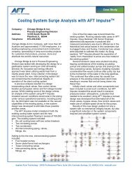
Figure 2 shows stagnation-pressure<br />
and Mach-number profiles for expansion<br />
choking and restriction choking;<br />
both involve supply air at 100 psia<br />
and 1,000°R discharging to 30 psia.<br />
Endpoint-choking behavior appears in<br />
Figure 7, discussed later.<br />
For a given process situation, the<br />
choked flowrate can be determined<br />
from Equation (10a), by inserting a<br />
Mach number of 1 into Equation (10b):<br />
where:<br />
(10a)<br />
(10b)<br />
These equations can be derived from<br />
the continuity equation [4, p.97].<br />
In practice, it is difficult to apply<br />
these equations to choked conditions,<br />
because the local conditions, P 0 and<br />
T 0 , are not known at the point of choking.<br />
For instance, to apply the equations<br />
to endpoint choking, one must<br />
calculate the stagnation pressure and<br />
temperature at the end of the pipe, upstream<br />
of the shock wave — but these<br />
two variables depend on the flowrate,<br />
which is not yet known.<br />
The only way to solve such a problem<br />
accurately is by trial and error:<br />
first, assume a flowrate and march<br />
down the pipe; if M reaches 1 before<br />
the end of the pipe, repeat the procedure<br />
with a lower assumed flowrate;<br />
repeat until M reaches 1 right at the<br />
pipe endpoint. Obviously, this calculation<br />
sequence is not practical without<br />
a computer.<br />
From the standpoint of pipe design<br />
or system operation, sonic choking<br />
sets a limit on the maximum possible<br />
flowrate for a given set of supply conditions.<br />
In particular, lowering the<br />
discharge pressure does not raise the<br />
flowrate. Figure 3 illustrates this for<br />
Figure 2. These stagnation-pressure and Mach-number profiles are for (left) expansion<br />
choking, involving a 2-in. pipe expanding to 3 in., and (right) restriction choking<br />
at a 0.6-area-ratio orifice in a 2-in. pipe<br />
5<br />
4<br />
3<br />
2<br />
1<br />
0<br />
0 0.2 0.4 0.6 0.8 1<br />
dP stag/P stag inlet<br />
Figure 3. In this adiabatic flow of 100-<br />
psia, 70F air, sonic choking occurs at<br />
63.6-psia or lower discharge pressure<br />
a 2-in. pipe carrying air that is supplied<br />
at 100 psia. Despite containing<br />
no physical restrictions, this system<br />
experiences endpoint choking at any<br />
discharge pressure below 63.6 psia.<br />
Some engineers misapply the concept<br />
of sonic choking and conclude<br />
that the sonic flowrate is the maximum<br />
possible through a given system<br />
for all conditions. In fact, however, the<br />
flowrate can be increased by raising<br />
the supply pressure. Indeed, the increased<br />
choked-flowrate presumably<br />
increases linearly with increased supply<br />
pressure (Figure 4).<br />
The pressure drop across the shock<br />
wave in choked flow cannot be calculated<br />
directly. 2 The only recourse is<br />
to use the choked flowrate as a new<br />
boundary condition on the pipe downstream<br />
of the shock wave (assuming<br />
that one is not dealing with endpoint<br />
choking) and to apply Equations (2) –<br />
(6) in the remaining pipes. The shockwave<br />
process is not truly isenthalpic,<br />
but (in accordance with Equation [4])<br />
instead entails constant stagnation<br />
enthalpy.<br />
Be aware that a given pipe can choke<br />
at more than one location along its<br />
length. This occurs when the choked<br />
flowrate set by the upstream choke<br />
point is applied to the pipes beyond<br />
the upstream shock wave, and the<br />
gas at this flowrate cannot reach the<br />
end of the pipe without experiencing<br />
2.“Normal shock tables” (perhaps more familiar<br />
to aeronautical engineers than to chemical engineers)<br />
apply only to supersonic flows, and are of<br />
no use for sonic or subsonic pipe flow.<br />
p stag/P stag inlet<br />
<strong>Choke</strong>d-flow rate, lb m /s<br />
4<br />
3<br />
2<br />
1<br />
Mach/number<br />
0 0 100 200 300 400 500 600<br />
Supply pressure, psia<br />
Figure 4. Increasing the supply pressure<br />
raises the choked flowrate (shown<br />
here for an adiabatic flow of steam)<br />
another shock wave. In fact, there is<br />
no limit to the number of choke points<br />
in a pipe, other than the number of<br />
possible geometric configurations that<br />
permit shock waves. The three mechanisms<br />
that cause choking can all occur<br />
in the same pipeline, in any combination.<br />
References [2] and [3] discuss<br />
calculation procedures for multiplechoking<br />
systems.<br />
Single-pipe adiabatic flow<br />
Before presenting compressible-flow<br />
equations that are generally applicable<br />
(Equations [13] and [14]), we consider<br />
two special cases: adiabatic and<br />
isothermal flow. Both are important<br />
in their own right. What’s more, analysis<br />
of the two (see below) leads to the<br />
guidelines that can help the engineer<br />
decide whether compressibility (with<br />
its far more-complex calculations)<br />
must be taken into account in a given<br />
process situation.<br />
The thermodynamic process a gas<br />
undergoes in constant-diameter adiabatic<br />
flow can be viewed in terms of<br />
entropy and static enthalpy. This<br />
process traces out a curve called the<br />
Fanno line 3 (Figure 5). The Fanno line<br />
neglects elevation changes, a safe assumption<br />
in most gas systems.<br />
According to the Second Law of Thermodynamics,<br />
the entropy increases as<br />
the gas flows through the pipe. Thus,<br />
depending on the initial state of the<br />
gas (either subsonic or supersonic), the<br />
3. Some authors show the Fanno line as a plot of<br />
temperature (rather than enthalpy) vs. entropy.
h<br />
h o = constant<br />
V 2<br />
2<br />
Heated<br />
Isothermal<br />
Figure 6. Adiabatic<br />
and isothermal flow do<br />
Sonic point<br />
s max<br />
s<br />
Temperature, ˚F<br />
110<br />
90<br />
70<br />
50<br />
Distance, ft.<br />
Case<br />
Mass<br />
flow (lb/s)<br />
Cooled 0.9197<br />
Adiabatic 0.8994<br />
Isothermal 0.8903<br />
Heated 0.8776<br />
In four situations shown<br />
here, 100-psia, 111°F air<br />
is fed into a 1-in. pipe 20 ft<br />
long. Outlet pressure is 60<br />
psia. Cooled flow has 30°F<br />
ambient temperature;<br />
heated flow, 220°F. The<br />
heat-transfer coefficients<br />
are 100 Btu/(h)(ft )(°F)<br />
Figure 5. Fanno lines, such as the one<br />
presented here, show enthalpy vs. entropy<br />
for adiabatic flow in a pipe<br />
process will follow either the upper or<br />
lower portion of the curve. Very few<br />
process situations entail supersonic<br />
flow in pipes, so we will focus on the<br />
subsonic (i.e., upper) portion.<br />
The stagnation enthalpy, h 0 , is constant<br />
because the system is adiabatic.<br />
However, the gas is accelerating, which<br />
causes the static enthalpy to decrease,<br />
in accordance with Equation (4). If the<br />
proper conditions exist, the gas will<br />
continue to accelerate up to the point<br />
at which its velocity equals the sonic<br />
velocity, where sonic choking begins.<br />
As Figure 5 shows, the enthalpy<br />
approaches the sonic point asymptotically.<br />
Accordingly, the thermodynamic<br />
properties experience intensely<br />
rapid change at the end of a sonically<br />
choked pipe. Examples of such change<br />
arise later in this article.<br />
The gas static temperature usually<br />
decreases as it travels along the<br />
pipe, due to the decreasing pressure.<br />
Under certain conditions, however, the<br />
reverse is true. The governing parameter<br />
in this regard is the Joule-Thompson<br />
coefficient [5, 8]. The points made<br />
in this article are (unless otherwise<br />
noted) applicable for either the cooling<br />
or heating case if the appropriate<br />
words are substituted, but we assume<br />
the cooling case for the sake of discussion.<br />
For more on Fanno flow see References<br />
[4, 6, 7].<br />
From Equations (2)– (6), the following<br />
equation can be derived for adiabatic<br />
flow of a perfect gas [4, p. 209]:<br />
(11a)<br />
(11b)<br />
Single-pipe isothermal flow<br />
In the second special case, isothermal<br />
flow, the static temperature of the gas<br />
remains constant. As already noted,<br />
the tendency is for gas to cool as it<br />
flows along a pipe. For the temperature<br />
to remain constant, an inflow of<br />
heat is required.<br />
When temperature is constant,<br />
Equations (2)–(6) become somewhat<br />
simpler. In Equation (5), for instance,<br />
density becomes directly proportional<br />
to pressure, and a perfect-gas analytical<br />
solution can be obtained:<br />
(12a)<br />
where the T subscript on L emphasizes<br />
that the system is isothermal.<br />
Integrating from 0 to L gives:<br />
(12b)<br />
To truly maintain isothermal flow<br />
up to the sonic point would require an<br />
infinite amount of heat addition. This<br />
leads to the strange but mathematically<br />
correct conclusion that for isothermal<br />
flow, sonic choking occurs at a<br />
Mach number less than 1. Practically<br />
speaking, it is not feasible to keep a<br />
gas flow fully isothermal at high velocities.<br />
For a more-complete discussion<br />
of isothermal flow in pipes, see Reference<br />
[4], pp. 265–269.<br />
One occasionally finds a misconception<br />
among engineers designing gas<br />
systems: that adiabatic and isothermal<br />
flow bracket all possible flow-<br />
consider the adiabatic case, where no<br />
heat is added but the gas cools. If heat<br />
is removed, the cooling will exceed<br />
that in adiabatic flow. Next consider<br />
isothermal flow, where the addition of<br />
heat keeps the gas static temperature<br />
constant. If more heat is added than<br />
required to maintain isothermal flow,<br />
the static temperature will increase.<br />
In summary, the heat-transfer environment<br />
plays a critical role in determining<br />
whether the gas flow is closer<br />
to adiabatic or isothermal. It is also<br />
the mechanism that can cause the gas<br />
flow to exceed the limits of the two<br />
special cases. Figure 6 demonstrates<br />
the different situations.<br />
General single-pipe equations<br />
For the general (neither adiabatic nor<br />
isothermal) case, in situations when<br />
the compressibility of the gas cannot<br />
be ignored, Equations (2)–(6) can<br />
be combined and, through calculus<br />
and algebra [3, 4], represented in differential<br />
form by Equations (13) and<br />
(14). Equation (13a) [1-3] is based on<br />
a fixed-length step between Locations<br />
1 and 2 along the pipe. The terms involving<br />
and Z account for the<br />
real- gas effects:<br />
Integration yields:<br />
where:<br />
Integrating from 0 to L along the<br />
length of the pipe gives: rates. However, this is not true. First, Conditions at Location 1 are known;<br />
(13a)<br />
(13b)<br />
(13c)
Cover Story<br />
T/T inlet<br />
T stag/T stag inlet<br />
1<br />
0.9<br />
0.8<br />
0.7<br />
0.6<br />
0.5<br />
the goal is to find those at Location 2 0.4<br />
0<br />
that satisfy the equations. There are<br />
multiple unknowns at Location 2, and<br />
much iteration is required.<br />
1.1<br />
In addition, some expression for the<br />
1<br />
0.9<br />
heat-transfer process is required in<br />
0.8<br />
order to apply the energy equation,<br />
0.7<br />
Equation (4). In a convective applica-<br />
0.6<br />
tion, this will usually require a con-<br />
0.5<br />
vection coefficient. For more details,<br />
see Reference [3].<br />
Another formulation of these equations<br />
is better suited for systems that<br />
incur either endpoint or expansion<br />
sonic choking. This method takes solution<br />
steps over equal Mach-number<br />
increments rather than length increments<br />
[1-3]:<br />
where:<br />
Integration yields:<br />
(14a)<br />
(14f)<br />
An increase in Mach number from<br />
M 1 to M 2 can be arbitrarily specified<br />
(say, by increments of 0.01); then, one<br />
computes the distance from x 1 to x 2<br />
that is required to obtain this change<br />
in Mach number. Again, extensive<br />
iteration is required because there<br />
are multiple unknowns at Location<br />
2. This method lets the engineer follow<br />
the rapidly changing conditions<br />
at the end of the pipe during choking<br />
(see Figure 7).<br />
0.4<br />
0.8<br />
1.0<br />
Mach number<br />
0.6<br />
T ambient /T inlet = 0.4<br />
0.4<br />
0.3<br />
0.2 0.4 0.6<br />
x/L<br />
0.8 1<br />
0<br />
1<br />
0.9<br />
1.0 0.8<br />
0.8<br />
0.6<br />
T ambient /T inlet = 0.4<br />
0 0.2 0.4 0.6<br />
x/L<br />
P stag/P stag inlet<br />
1<br />
0.9<br />
0.8<br />
0.7<br />
0.6<br />
0.5 T ambient /T inlet = 0.4<br />
0.6<br />
0.8<br />
1.0<br />
0.2<br />
0.2 0.4 0.6 0.8 1<br />
x/L<br />
0.7<br />
0.6<br />
0.6<br />
T<br />
0.5 ambient /T inlet = 0.4<br />
0.4<br />
0.3<br />
0.2<br />
0.1<br />
0.8 1 0 0.2 0.4 0.6<br />
x/L<br />
1.0<br />
0.8<br />
0.8 1<br />
Figure7. These typical, dimensionless property variations were taken with respect to<br />
air supplied at 100 psia and 1,000R into a 2-in. pipe 100 ft long, under conditions<br />
providing a sonically choked discharge. The curves relate to four ambient-temperature<br />
conditions. Similar curves could be drawn showing other parameters, such as density,<br />
enthalpy and static pressure, as functions of the distance along the pipe<br />
Simplification error : How big<br />
As already noted, a key question arises:<br />
How much error is introduced if the engineer<br />
sidesteps the calculational complications<br />
of equations such as Equations<br />
(13) and (14) by instead making<br />
the incompressible-flow assumption<br />
Adiabatic flow: In the fully adiabatic-flow<br />
case (that is, assuming a<br />
perfectly insulated pipe), Figure 8 provides<br />
typical answers to that question,<br />
with respect to three specific cases.<br />
They involve, respectively, the flow<br />
of three widely used fluids: air, steam<br />
and methane (the last-having properties<br />
similar to those of natural gas).<br />
The results in Figure 8 were developed<br />
by building models for both compressible<br />
and incompressible flow. The<br />
latter models used the arithmetic average<br />
fluid density, and assumed that<br />
the viscosity was constant. The inlet<br />
stagnation conditions for the three<br />
streams were as follows:<br />
Air: 100 psia, 70° F<br />
Steam: 500 psia, 600° F<br />
Methane: 500 psia, 100° F<br />
All pipes were standard steel, with<br />
a roughness of 0.00015 ft.<br />
With respect to each of the three<br />
gases, we compared the calculated<br />
flowrates for the two cases. The difference<br />
between the two is the error that<br />
results from using the incompressible<br />
assumption. The error is plotted in<br />
Figure 8 for 1-in. pipe of three different<br />
lengths.<br />
The clustering of the air, steam and<br />
methane results confirms that the pipe<br />
pressure-drop ratio and the ratio of<br />
length to diameter are appropriate parameters<br />
to use for generalization when<br />
focusing on a specific pipe diameter.<br />
For the conditions modeled, air followed<br />
the ideal gas law closely. However,<br />
the steam and methane conditions<br />
did not follow the ideal gas law, with<br />
compressibility factors (corrections for<br />
non-ideality) ranging from 0.92 to 0.97.<br />
From these data, it appears that the<br />
generalizations implied by Figure 8 can<br />
be applied to non-ideal gases.<br />
To extend the generalization, the<br />
preceding calculations were repeated<br />
for air flowing in pipes with diameters<br />
of 3, 6, 12 and 24 in., increasing the<br />
pipe length each time to maintain the<br />
L/D ratios of 50, 200 and 1,000. Results<br />
(not shown) indicate that the error is<br />
always larger than for the 1-in.dia pipe<br />
with the same L/D. For 24-in. pipe, the<br />
error is larger by over a factor of two.<br />
Why does the incompressible-flowassumption<br />
error increase as the pipe<br />
diameter increases The reason relates<br />
to the pipe-roughness data. As<br />
the pipe diameter increases, the absolute<br />
roughness remains constant, resulting<br />
in a decreasing relative roughness<br />
(e/D). This leads to lower friction<br />
factors, which leads to larger velocities<br />
for a given pressure drop, and, thus,<br />
greater error.<br />
We have also developed a more<br />
widely applicable tool than Figure 8<br />
for assessing the error introduced by<br />
assuming incompressible flow. The<br />
more-appropriate parameter to relate<br />
gas-flow supply and discharge<br />
conditions is not the L/D ratio, but<br />
the ratio of fL/D (a choice commonly<br />
employed in gas-flow tabulations, and<br />
consistent with the arrangement of<br />
Equations [11] and [12]). Plotting the
Incompressible-flow rate error, %<br />
30<br />
40 0.1 0.5 30<br />
25<br />
L/D = 50<br />
Air<br />
1.0<br />
20 T /T = 0.6<br />
L/D = 200 Steam<br />
Sonic choking above this line<br />
ambient inlet<br />
30<br />
20<br />
Methane<br />
10<br />
0.8<br />
1.5<br />
15<br />
20<br />
0<br />
fL/D=3<br />
1.2<br />
10<br />
5<br />
L/D = 1000<br />
-10<br />
10 10 1.5<br />
5<br />
15 30<br />
-20<br />
50<br />
0 0<br />
-30<br />
0 0.2 0.4 0.6 0.8 1 0 0.2 0.4 0.6 0.8 0 0.1 0.2 0.3 0.4 0.5 0.6<br />
dP stag/P stag, inlet dP stag/P stag, inlet dP stag/P stag, inlet<br />
<strong>Flow</strong> rate error, %<br />
Error, %<br />
FIGURE 8. The pipe pressure-drop ratio<br />
and the ratio of pipe length to diameter<br />
are appropriate parameters for generalizing<br />
about the error that is introduced<br />
when assuming incompressible flow<br />
incompressible-flow-assumption error<br />
against this parameter makes it possible<br />
to summarize the information on a<br />
single curve for each fL/D value, which<br />
applies for all pipe diameters.<br />
Such an error map appears in Figure<br />
9. It is based on an iterative program,<br />
Compressible <strong>Flow</strong> Estimator<br />
(CFE), developed by the author and<br />
being made available as a free download<br />
at http://www.aft.com/cfe.htm.<br />
The results shown in Figure 9 are<br />
of general applicability. Various specific<br />
heat ratios, , and<br />
compressibility factors, Z, have been<br />
entered into the CFE, and the results<br />
always fall along the lines shown in<br />
Figure 9. This error map is also<br />
consistent with real-sys- tem<br />
predictions based on more-sophisticated<br />
calculation methods. Accordingly,<br />
Figure 9 is recommended to the<br />
engineer for general use as a guide in<br />
assessing compressibility in pipes.<br />
Keep in mind, though, that Figure<br />
9 assumes adiabatic flow. Additional<br />
error can result from flows involving<br />
heat transfer. The relative importance<br />
of heat transfer is addressed in the<br />
next section.<br />
Finally, note that the direction of<br />
the incompressible-flow-assumption<br />
error is to overpredict the flowrate. Or,<br />
stated differently, for a given flowrate,<br />
it will underpredict the pressure drop.<br />
Unfortunately for typical pipe-system<br />
applications, neither of these conclusions<br />
is consistent with conservative<br />
design.<br />
The sequence of steps that underlie<br />
the CFE program are available from<br />
the author. Also available from him are<br />
modified sequences, for handling situations<br />
in which (1) the endpoint static<br />
pressure rather than the stagnation<br />
pressure are known, or (2) the temperature<br />
and flowrate are known but the<br />
endpoint stagnation pressure is not.<br />
Effect of heat transfer: The author<br />
knows of no general relationship<br />
showing the effect of heat transfer on<br />
FIGURE 9. This map shows the error<br />
(overprediction) in flowrate prediction for<br />
a single pipe due to using incompressible-flow<br />
assumptions rather than an<br />
adiabatic compressible-flow calculation<br />
the size of the incompressible-flow-assumption<br />
error. However, some insight<br />
can be gained from comparing relevant<br />
compressible-flow calculations<br />
(setting aside for a moment our pre-<br />
occupation with the incompressibleflow-assumption<br />
error). Computer<br />
models were constructed to determine<br />
the difference in flowrate for air at different<br />
ambient temperatures.<br />
The difference in flowrate for air<br />
with different ambient temperatures<br />
as compared to the compressible adiabatic<br />
case appears in Figure 10. It can<br />
be seen that cooling a gas may result<br />
in a greatly increased flowrate. In<br />
contrast, heating a gas can cause the<br />
flowrate to decrease significantly.<br />
Accordingly, if an engineer is trying<br />
to design for a minimum flowrate, a gas<br />
stream that is cooling works in his or<br />
her favor by causing an underprediction<br />
of the flowrate when using adiabatic<br />
flow methods. When this error is<br />
combined with that of an incompressible-flow<br />
assumption, which overpredicts<br />
the flow, these two errors work in<br />
opposite directions, in part cancelling<br />
each other out. Conversely, a gas being<br />
heated adds further error on top of the<br />
incompressible-flow-assumption error,<br />
causing even more overprediction of<br />
the flowrate.<br />
In many gas-pipe-system designs,<br />
the delivery temperature is as important<br />
as the delivery flowrate and pressure.<br />
In those cases, the heat-transfer<br />
characteristics of the pipe system take<br />
on the highest importance, and neither<br />
adiabatic nor isothermal methods<br />
—let alone incompressible-flow assumptions<br />
— can give accurate predictions.<br />
Unless the gas flow is very low<br />
and can be adequately calculated with<br />
incompressible methods, the designer<br />
is left with no choice but to perform<br />
a full compressible flow calculation.<br />
This means solving Equations (2)–(6)<br />
with a suitable relationship for the<br />
heat transfer to be used in Equation<br />
Figure 10. When a pipe is treated as adiabatic<br />
but actually has heat transfer, the flowrate<br />
prediction error can be sizable, even without<br />
an incompressible-flow assumption. The<br />
case here is for 100-psia, 70F air entering an<br />
uninsulated steel pipe with L/D ratio of 200<br />
(4), or using more-convenient forms<br />
of these equations, such as Equations<br />
(13) or (14). Realistically, this requires<br />
appropriate software.<br />
Network complications<br />
When applying the concepts in this article,<br />
and in particular the use of the<br />
CFE program that underlies Figure<br />
9, to a pipe network, the number of<br />
variables increases and the difficulty<br />
in assessing the potential error likewise<br />
increases. To investigate possible<br />
error-estimating methods, we have<br />
constructed simple flow models, one<br />
for incompressible flow and the other<br />
for compressible flow, of a manifolding<br />
pipe system. For simplicity, the compressible-flow<br />
model assumed that all<br />
flows are adiabatic. The basis is a 110-<br />
psia air system that enters a header<br />
and flows to three pipes at successive<br />
points along the header, terminating<br />
in a known pressure of 90 psia.<br />
For each pipe in the system, the<br />
predicted fL/D and pressure-drop<br />
ratio have been determined from the<br />
incompressible-flow model. The resulting<br />
data have been entered into<br />
the CFE program for each pipe, and<br />
an approximate error generated for<br />
each. Then, starting from the supply,<br />
a path has been traced to each terminating<br />
boundary (of which there are<br />
three). The error for each pipe in the<br />
path has been summed, and then divided<br />
by the number of pipes in the<br />
path, giving an average error. This<br />
average has been compared to the<br />
actual difference between the results<br />
of the incompressible- and compressible-flow<br />
models.<br />
Overall the comparison has proved<br />
favorable. However, applying CFE to<br />
this networked system underpredicts<br />
the actual error from the detailed models<br />
by up to 20%. The first pipe in the<br />
header shows the largest error, and the<br />
last pipe the smallest. As in the singlepipe<br />
calculations, the incompressible
Cover Story<br />
method overpredicts the flowrate.<br />
In short, extra care should be taken<br />
when interpreting the meaning of incompressible-flow<br />
methods applied to<br />
gas pipe networks.<br />
Rethinking the rules of thumb<br />
The information presented up to now<br />
provides a basis for critiquing a number<br />
of rules of thumb upon which engineers<br />
often depend when dealing<br />
with gas flow.<br />
Adiabatic and isothermal flow:<br />
One rule of thumb is the myth that<br />
adiabatic and isothermal flow bracket<br />
all flowrates. They do not, as has already<br />
been noted.<br />
40%-pressure-drop rule: A common<br />
belief is what can be called the 40%-<br />
pressure-drop rule. Presented in a variety<br />
of handbooks, it states that if the<br />
pipe pressure drop in a compressibleflow<br />
system is less than 40% of the<br />
inlet pressure, then incompressibleflow<br />
calculation methods can be safely<br />
employed, with the average density<br />
along the pipe used in the equations.<br />
In the handbooks, it is not made<br />
clear whether the pressure drop ratio<br />
is to be based on the stagnation or the<br />
static pressures. (In the author’s experience,<br />
engineers apply the rule more<br />
frequently using stagnation-pressure<br />
ratios.) In any case, Figures 8 and 9<br />
make it clear that the 40%-pressuredrop<br />
rule has no validity unless associated<br />
with a specific L/D ratio. Accordingly,<br />
this rule of thumb is highly<br />
misleading, and should be discarded<br />
by the engineering community.<br />
<strong>Choke</strong>d air flow at 50% pressure<br />
drop: An equation sometimes used<br />
as a rule of thumb to assess the likelihood<br />
of sonic choking is as follows (see,<br />
for instance, Reference [4], p 94):<br />
(15)<br />
where p* is the critical static pressure<br />
at sonic velocity and p 0 the local stagnation<br />
pressure. For air, the specific<br />
heat ratio is 1.4, so the pressure ratio in<br />
the equation works out to 0.5283. This<br />
However, Equation (15) breaks<br />
down for pipe-system analysis when<br />
pipe friction becomes a factor. The<br />
reason is that the stagnation pressure<br />
in the equation is the pressure at the<br />
upstream side of the shock wave. If<br />
there is any pressure drop in the pipe<br />
from the supply pressure to the shock<br />
wave, then the supply pressure cannot<br />
be used in Equation (15). Instead, the<br />
local stagnation pressure at the shock<br />
wave must be used — but this is not<br />
known, unless the pressure drop is<br />
calculated using other means.<br />
In short, Equation (15) cannot be<br />
used to predict the supply and discharge<br />
pressures necessary for sonic<br />
choking unless the piping has negligible<br />
friction loss.<br />
Other simplified compressible-flow<br />
methods: A variety of simplified gasflow<br />
equations, often based on assuming<br />
isothermal flow, crop up in the practical<br />
engineering literature. These typically<br />
have several drawbacks that are not always<br />
acknowledged or recognized:<br />
• Most gas flows are not isothermal.<br />
In such cases, one cannot know how<br />
much error is introduced by the assumption<br />
of constant temperature.<br />
Related to this is the general issue of<br />
the importance of heat transfer on the<br />
gas flow, already mentioned<br />
• Simplified equations typically do<br />
not address sonic-choking issues<br />
• These equations are of no help when<br />
the delivery temperature is important<br />
• The simplified equations break<br />
down at high Mach numbers<br />
• Unrealistically, the entire pipe is<br />
solved in one lumped calculation,<br />
rather than using a marching solution<br />
• It is difficult to extend the equations<br />
to pipe networks<br />
In summary, simplified compressibleflow<br />
equations can be an improvement<br />
over assuming incompressible flow,<br />
but numerous drawbacks limit their<br />
usefulness.<br />
ible-flow methods and estimation equations<br />
in this article to such systems.<br />
The methods discussed in this article<br />
can help the engineer assess endpoint<br />
sonic choking, but restriction and expansion<br />
choking are somewhat more<br />
complicated. Accordingly, the estimation<br />
methods in this article may not be<br />
applied to all choking situations.<br />
For new designs that require a lot of<br />
pipe, the engineer should consider the<br />
potential costs savings if smaller pipe<br />
sizes can be used. If significant cost<br />
savings prove to be possible, it may be<br />
prudent to invest in developing a detailed<br />
model that can more accurately<br />
determine the system capability over<br />
a range of pipe sizes. A detailed model<br />
may also help assess the wisdom of<br />
making modifications proposed for an<br />
existing system.<br />
■<br />
Edited by Nicholas P. Chopey<br />
References:<br />
1. Winters, B.A., and Walters, T.W., X-34 High<br />
Pressure Nitrogen Reaction Control System<br />
Design and Analysis, NASA Thermal Fluid<br />
Analysis Workshop, Houston, Tex., 1997.<br />
2. Walters, T.W., and Olsen, J.A., Modeling<br />
Highly Compressible <strong>Flow</strong>s in Pipe Networks<br />
Using a Graphical User Interface,<br />
ASME International Joint Power Generation<br />
Conference, Denver, Colo., 1997.<br />
3. “AFT Arrow 2.0 User’s Guide,” <strong>Applied</strong> <strong>Flow</strong><br />
<strong>Technology</strong>, Woodland Park, Colo., 1999.<br />
4. Saad, M.A., “Compressible Fluid <strong>Flow</strong>,” 2nd<br />
Ed., Prentice-Hall, Englewood Cliffs, NJ, 1993.<br />
5. Carroll, J.J., Working with Fluids that Warm<br />
Upon Expansion, Chem. Eng., pp. 108–114,<br />
September 1999.<br />
6. Anderson, J.D., Jr., “Modern Compressible<br />
<strong>Flow</strong>: With Historical Perspective,” McGraw-<br />
Hill, New York, N.Y., 1982.<br />
7. Shapiro, A.H., “The Dynamics and Thermodynamics<br />
of Compressible Fluid <strong>Flow</strong>,” 2<br />
vols., Ronald, New York, N.Y., 1953.<br />
8. Barry, John, Calculate Physical Properties for<br />
Real <strong>Gas</strong>es, Chem. Eng., pp. 110–114, April<br />
1999.<br />
9. <strong>Flow</strong> of Fluids Through Valves, Fittings, and<br />
Pipe, Technical Paper No. 410, Crane Co., Joliet,<br />
Ill., 1988.<br />
Author<br />
Final thoughts<br />
Compressors, blowers and fans raise<br />
results in a pressure drop ratio of near the system pressure and density. These<br />
47% (in other words, about 50%) to bring changes in properties inside the gaslation<br />
software,<br />
about sonic choking. For gases with dif- flow system further limit the applicabilferent<br />
specific heat ratios, the pressure ity of incompressible methods, beyond<br />
drop ratio will differ somewhat, in ac- the cautions already discussed. Take<br />
cordance with Equation (15).<br />
special care in applying the incompress-<br />
Trey Walters, P.E., is President<br />
and Director of Software<br />
Development for <strong>Applied</strong><br />
<strong>Flow</strong> <strong>Technology</strong> (AFT, 400<br />
W. Hwy 24, Suite 201, P.O.<br />
Box 6358, Woodland Park,<br />
CO 80866-6358; Phone: 719-<br />
686-1000; Fax: 719-686-1001;<br />
E-mail: treywalters@aft.com).<br />
He founded the company, a<br />
developer of Microsoft-Windows-based<br />
pipe-flow-simu-<br />
in 1993. Previously, he was a<br />
senior engineer in cryogenic rocket design for<br />
General Dynamics, and a research engineer in<br />
steam-equipment design for Babcock & Wilcox.<br />
Walters holds B.S. and M.S. degrees in mechanical<br />
engineering from the University of California<br />
at Santa Barbara, and is a registered engineer<br />
in California.<br />
Reprinted from the January 2000 issue of Chemical Engineering. © 2006 Access Intelligence, LLC.