

NBOX/XNC220 Node Controller Data Sheet - Trend
NBOX/XNC220 Node Controller Data Sheet - Trend
NBOX/XNC220 Node Controller Data Sheet - Trend

Create successful ePaper yourself
Turn your PDF publications into a flip-book with our unique Google optimized e-Paper software.
<strong>Data</strong> <strong>Sheet</strong><br />
<strong>NBOX</strong>/<strong>XNC220</strong><br />
<strong>Node</strong> <strong>Controller</strong><br />
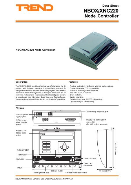
<strong>NBOX</strong>/<strong>XNC220</strong> <strong>Node</strong> <strong>Controller</strong><br />
Description<br />
The <strong>NBOX</strong>/<strong>XNC220</strong> provides a flexible way of interfacing the IQ<br />
system with 3rd party systems. It utilises both standard IQ<br />
configuration modules, and the Custom Language (TCL) to present<br />
information from other systems as though it were from an IQ<br />
controller. It also allows parameters within the 3rd party system<br />
to be adjusted from IQ system Supervisor, and Tool software.<br />
It has an optional integral 2-line display, and limited I/O capability.<br />
Features<br />
• Flexible method of interfacing with 3rd party systems.<br />
• Custom Language (TCL) compatible.<br />
• Standard IQ configuration modules.<br />
• 230 Vac, or 24 V versions.<br />
• Small footprint.<br />
• 3 point mounting.<br />
• 2 digital inputs, and 1 SPCO relay output.<br />
• Optional integral 2-line display.<br />
Physical<br />
SPCO relay (digital) output<br />
230 Vac power<br />
supply option<br />
24 Vac or dc<br />
power supply<br />
option<br />
230V NC NO C<br />
~<br />
24V<br />
MODEM<br />
RDS/RS232<br />
!<br />
RS232 3rd party system<br />
connector<br />
(for /485 option see over)<br />
integral 2-line<br />
display panel<br />
option<br />
DP<br />
Relay O/P LED<br />
Status LEDs<br />
A<br />
B<br />
C<br />
D<br />
181 mm (7.125”)<br />
OK<br />
Input LEDs<br />
1 2<br />
TX<br />
RX<br />
<strong>Trend</strong> Lan LEDs<br />
inputs<br />
12345678910<br />
<strong>Trend</strong> Lan<br />
connector<br />
earth (ground) bus<br />
230 mm (9.05”)<br />
address/baud rate switch<br />
70 mm (2.75”)<br />
<strong>NBOX</strong>/<strong>XNC220</strong> <strong>Node</strong> <strong>Controller</strong> <strong>Data</strong> <strong>Sheet</strong> TA200018 Issue 1/D 11/01/07<br />
1
<strong>NBOX</strong>/<strong>XNC220</strong><br />
<strong>Data</strong> <strong>Sheet</strong><br />
Physical (continued)<br />
/485 only<br />
adaptor cable 40 mm<br />
(1.57”), supplied<br />
33 mm (1.3”)<br />
3rd party system connection (RS485)<br />
adaptor cable 3 m<br />
(9’9.9”), supplied 16 mm<br />
136 mm (5.35”)<br />
(0.62”)<br />
33 mm (1.29”)<br />
9 Way D type<br />
9 Way D type<br />
RS232/485 converter<br />
25 Way D type<br />
FUNCTIONALITY<br />
The <strong>NBOX</strong>/<strong>XNC220</strong> enables interfacing between the IQ system, and 3rd party systems. The functionality can be divided into two<br />
sections the firmware, and the hardware.<br />
FIRMWARE<br />
The firmware within the <strong>NBOX</strong>/<strong>XNC220</strong> consists of two parts: the device part, and the TCL part. The device part (standard IQ2<br />
v3.2 firmware) consists of a number of standard IQ configuration modules, and functions in exactly the same way as a IQ controller.<br />
These modules can be linked together to form a strategy to manipulate the data from the 3rd party system in the normal way. The<br />
TCL part runs a Custom Language (TCL) program. It communicates with the 3rd party system, passing information from the analogue<br />
and digital arrays in the device part to the 3rd party system, and writing values from the 3rd party system to the analogue and digital<br />
arrays in the device part. It can also receive, and send messages to/from the IQ system current loop Lan via a second address<br />
(set up with a Comport module).<br />
Configuration: The device part of the <strong>NBOX</strong>/<strong>XNC220</strong> uses the<br />
standard IQ configuration mode which enables configuration via<br />
the network. SET can be used to create a strategy data file (.IQF)<br />
which can then be downloaded to the controller. SET can also<br />
be used to upload, and download .IQF files for backup purposes.<br />
The TCL part is configured using a TCL Programming Tool to<br />
download a TCL program.<br />
Communications: When operating as part of a Building<br />
Management System, the IQ22x will be connected to other devices<br />
via the IQ system Network. This means that information within<br />
the IQ22x can be accessed using one of the IQ system supervisor<br />
programs, or passed to other IQ controllers using inter-controller<br />
communication, enabling the sharing of information across the<br />
whole system.<br />
When connected to the network the controller can use up to 2<br />
different addresses. One address is for the controller itself (set<br />
by front panel switch), and the second is optional, and is used<br />
by a comport module (communications from TCL code). There<br />
are 2 comport modules, but one would be used for the<br />
RS232(RS485) connection to the 3rd party system.<br />
The controller’s address is set by a switch, and the comport<br />
addresses are set up in the strategy configuration (comport<br />
modules).<br />
Custom Language: This is a programming language, based on<br />
BASIC, which enables interfacing between the IQ System, and<br />
3rd party systems. A full description of the language can be<br />
found in the Custom Language (TCL) Manual.<br />
Address module: The address module functions as described<br />
in the IQ Configuration Manual plus Addendum, except that the<br />
local supervisor address parameter is ignored because it is<br />
used for connection to the 3rd party system.<br />
store module: Store modules are used to hold strings of<br />
information that can be assessed by the TCL program.<br />
Each store module can hold a sting of up to 40 characters. The<br />
store is accessed in configuration by using ‘s’ followed by the<br />
module number (e.g. s1 specifies store module 1). Store modules<br />
have a single parameter ‘$’ which holds the 40 character string.<br />
The TCL program reads from the store modules using the STORE$<br />
function (described in the TCL Manual).<br />
Parameter<br />
Description<br />
String<br />
The string that the module is to store. It can<br />
be up to 40 characters long.<br />
Modules: The strategy within the device part consists of a<br />
number of individual functional blocks known as configuration<br />
modules. These blocks can be linked in various combinations to<br />
perform manipulation of parameters from the 3rd party system.<br />
The table lists the different types of configuration modules and<br />
the number of each type available within the <strong>NBOX</strong>/<strong>XNC220</strong>.<br />
Module<br />
Type<br />
Number<br />
Module<br />
Type<br />
ID<br />
$<br />
Number<br />
† Sensor<br />
32<br />
† Critical<br />
Alarm<br />
4<br />
‡ Sensor<br />
type<br />
10<br />
† Alarm History<br />
20<br />
† Loop<br />
16<br />
† IC Comms<br />
16<br />
† Function<br />
90<br />
† Digital<br />
Inputs<br />
48<br />
† Logic<br />
90<br />
† Fast<br />
Sequence<br />
8<br />
† Driver<br />
12<br />
† Zone<br />
5<br />
† Knob<br />
30<br />
† Schedule<br />
8<br />
† Switch<br />
20<br />
† Calendar<br />
20<br />
‡ Sensor<br />
log<br />
20<br />
† User<br />
Password<br />
6<br />
† Sequence<br />
step<br />
240<br />
† Sequence<br />
time<br />
1 s<br />
† Analogue<br />
<strong>Node</strong>s<br />
256<br />
† Digital<br />
<strong>Node</strong>s<br />
506<br />
page<br />
30<br />
group<br />
10<br />
route<br />
50<br />
destination<br />
10<br />
New alarm log 100<br />
Display<br />
140<br />
* Comport<br />
2 Directory<br />
25<br />
* store<br />
50<br />
† Explained in IQ Configuration Manual. ‡ Explained in IQ Config.<br />
Manual Addendum. * Explained in this document.<br />
2 <strong>NBOX</strong>/<strong>XNC220</strong> <strong>Node</strong> <strong>Controller</strong> <strong>Data</strong> <strong>Sheet</strong> TA200018 Issue 1/D 11/01/07
<strong>Data</strong> <strong>Sheet</strong><br />
<strong>NBOX</strong>/<strong>XNC220</strong><br />
FIRMWARE (continued)<br />
Full details of the modules are given in the IQ Configuration<br />
Manual and Addendum. The <strong>NBOX</strong>/<strong>XNC220</strong> contains the normal<br />
IQ2 v3.1 features as described in the IQ Configuration Manual<br />
Addendum; Engineers Journal (J), I/O Summary (i/o), Loader<br />
Issue (R(c),’c’ lower case), Serial Number (R(s), ‘s’ lower case,<br />
Supply Frequency Option, Enhanced Logging.<br />
Comport module: Comport modules are used to define the<br />
setup of serial ports used to communicate with the 3rd party<br />
system, and IQ system ports used to enable the TCL part to<br />
communicate directly over the IQ system network. Comport<br />
modules are assessed in configuration by using ‘c’ followed by<br />
the module number (e.g. c1 specifies comport module 1). The<br />
parameters held within a particular comport module vary<br />
depending on whether it is a serial port, or a IQ system port.<br />
Each module has the following parameters:<br />
Parameter<br />
Description<br />
Label<br />
20-character user-friendly label for the<br />
module<br />
P ort Type The type of port the module is defining.<br />
Range = Serial, or IQ system Lan<br />
The other parameters vary depending on the port type that has been<br />
selected. If a serial port has been specified the following parameters<br />
need to be defined.<br />
Parameter<br />
Description<br />
B aud Rate The baud rate of the port.<br />
Range = 300 baud, 600 baud, 1200 baud,<br />
2400 baud, 4800 baud, 9600 baud, or<br />
19200 baud<br />
D ata Bits The required number of data bits.<br />
Range = 7 or 8<br />
P arity The partity that is to be used.<br />
Range = Odd, or Even<br />
Port<br />
The number of the com port being used.<br />
Number<br />
Rx The RX terminator character.<br />
Termination Range = 0 to 255<br />
S top Bits The required number of stop bits.<br />
Range = 1, or 2<br />
T imeout The timeout in milliseconds.<br />
Range = 0 to 32767<br />
ID<br />
$<br />
Y<br />
ID<br />
B<br />
D<br />
P<br />
N<br />
R<br />
S<br />
T<br />
If an IQ system port has been specified the following parameters<br />
need to be defined:<br />
Parameter<br />
Description<br />
Destination The network address to which the next<br />
Address message will be sent.<br />
Range 1 to 119 excluding addresses 2, 3,<br />
and 10.<br />
Destination The Lan number of the device to which the<br />
Lan next message will be sent.<br />
Range 1 to 119 excluding numbers 2, 3,<br />
and 10.<br />
Own The IQ network address of the por t.<br />
Address Range 1 to 119 excluding addresses 2, 3<br />
and 10.<br />
If set to zero the address wil be the<br />
address switch setting plus 1.<br />
T x Protocol The<br />
protocol used for transmission.<br />
ID<br />
D<br />
Note that for the /485 option , the Baud rate and <strong>Data</strong> bits must be<br />
set to match those of the interface. The following settings are<br />
possible 1200,8; 2400,8; 4800,8; 9600,8; 19200,8; (baud rate, data<br />
bits respectively).<br />
I/O Channels: Care should be taken to distinguish between<br />
configuration channel numbers used in configuration mode and<br />
printed on the board (input channels 1 to 2, relay output channel 8)<br />
and external connection numbers shown on the label (numbered<br />
differently, inputs 1 to 2 and relay output 16). Once the configuration<br />
channel is selected in configuration mode, the external connection<br />
is displayed alongside.<br />
L<br />
A<br />
P<br />
<strong>NBOX</strong>/<strong>XNC220</strong> <strong>Node</strong> <strong>Controller</strong> <strong>Data</strong> <strong>Sheet</strong> TA200018 Issue 1/D 11/01/07<br />
3
12345678910<br />
<strong>NBOX</strong>/<strong>XNC220</strong><br />
<strong>Data</strong> <strong>Sheet</strong><br />
HARDWARE<br />
Unit: The <strong>NBOX</strong>/<strong>XNC220</strong> is in a plastic enclosure with a<br />
transparent plastic flip-up terminal cover. It has a 3 point mounting<br />
to facilitate installation. An optional metal enclosure with cable<br />
glanding knockouts (ENCLS/MBOX/IQ22x) is available.<br />
IQ system Network: The network terminals facilitate connection<br />
of 2 wire cables. The address and baud rate (19k2, 9k6, or 1k2) are<br />
selected by switches. The standard IQ system network node<br />
features are included (TX, RX, and network OK , indicators,<br />
bypass relay, and network alarm generation).<br />
Connectors: 2 part connectors are used throughout to facilitate<br />
wiring. A bus bar is provided for screen termination.<br />
Address/Baud rate switch: The address on the Lan is set by<br />
poles 1 to 7 in range 1, 4 to 9, 11 to 119 and must be unique on<br />
the Lan. The baud rate is set by poles 8 to 10 in the range 1k2,<br />
9k6, 19k2 and must match the other nodes on the Lan. The<br />
address/baud rate switch may also be used to perform a strategy<br />
cleardown; this is done by setting all the address/baud rate poles<br />
to zero before power up (see Installation Instructions, TG200019<br />
sheet 3 and IQ Configuration Manual Addendum). For this reason<br />
the address should normally be set non-zero.<br />
RS485 to 3rd Party System: The /485 option has an RS232/RS485<br />
converter module which is connected to the rear of the unit by<br />
means of a 40 mm 25 way female D connector to 9 Way male D<br />
connector cable. The converter module is connect to the 3rd Party<br />
System by a 3 metre screened 9 way male D connector to open ends<br />
2 wire cable, and screen. Both of these adapter cables are supplied<br />
with the unit.<br />
9 W D male 9 W D male<br />
3rd Party<br />
<strong>NBOX</strong>/<strong>XNC220</strong><br />
40 mm<br />
System<br />
3 m<br />
25 W D female<br />
(9.99”) cut ends<br />
DIP switches<br />
Note: The internal wiring to the rear RS232 plug is non-standard<br />
and is only intended for the <strong>NBOX</strong>/<strong>XNC220</strong>/485 application. If<br />
any other device were to be connect to this plug, damage may<br />
occur.<br />
The converter module has DIP switches which can be set to<br />
match the communications type being use.<br />
ON<br />
SW1 SW2 SW3 SW4 SW5 SW6<br />
1<br />
2 3 4 5 6<br />
RS485 port is 4-wire OFF<br />
OFF OFF OFF do not set to this<br />
RS485 port is 2-wire ON<br />
OFF OFF ON 1200,8<br />
RS485 receiver is enabled only<br />
OFF ON OFF 2400,8<br />
when transmitter is disabled (RS485) OFF<br />
OFF ON ON 4800,8<br />
RS485 receiver is always enabled ON<br />
ON OFF OFF 9600,8<br />
RS485 transmitter enable is controlled ON OFF ON do not set to this<br />
(Slave on 4-wire RS485)<br />
OFF<br />
ON ON OFF 19200,8<br />
RS485 transmitter always enabled ON<br />
(Master on 4-wire RS485) ON ON ON do not set to this<br />
If a 4 wire RS485 is used, the 3 m cable needs to be replaced<br />
by a 4 wire cable (plus screen).<br />
GND 9<br />
TXA (0) 8<br />
RXB (I) 7<br />
GND 6<br />
4-wire RS485<br />
5<br />
4<br />
3<br />
2<br />
1<br />
GND<br />
GND<br />
TXB (0)<br />
RXA (I)<br />
GND<br />
2-wire RS485<br />
GND 9<br />
A (I/0) 8<br />
N/C 7<br />
GND 6<br />
DB9 Female<br />
1+4+5+6+9 are internally interconnected<br />
5<br />
4<br />
3<br />
2<br />
1<br />
GND<br />
GND<br />
B (I/0)<br />
N/C<br />
GND<br />
A or B: Following RS485 standards, the RS422/485 connections<br />
above are marked A and B. They are defined as follows: When<br />
the RS232 TX input is at the RS232 HIGH level the A output is at<br />
the RS485 HIGH level (+5V nominally) and the B output is at the<br />
RS485 LOW level (0V nominally).<br />
When connecting to other RS485 equipment, you may encounter<br />
markings such as HI/LO or +/-. Such non-standard markings are<br />
unclear and you may need to experiment. Normally, one assumes<br />
that the converter’s A/B corresponds to the other devices’s A/B,<br />
HI/LO or +/- marking respectively but sometimes, this is wrong.<br />
One simple way to help establish which is which is to measure<br />
the voltages on the other product when no communications is<br />
taking place: B should be more positive than A.<br />
RS422/485 Grounding: A connection between the converter’s<br />
GND and the other device(s) interface ground is highly desirable<br />
for proper noise immunity. The cable shield can be used for this<br />
connection However, unless the other device’s interface is<br />
isolated (i.e. floating) there is a risk of a ground loop current and<br />
this can result in equipment damage. In such a situation the GND<br />
connection can be omitted but only if the common mode voltage<br />
(the ground potential difference between the two interfaces) is<br />
within the common mode voltage range of -0.5 V to +5 V.<br />
Digital Inputs<br />
(external connections 1 & 2, configuration channels IN1, IN2)<br />
# 8<br />
O A M<br />
1 <br />
<br />
+ 8<br />
Battery Backup: Details about the strategy configuration, TCL<br />
program, time and date, and logged data are stored in RAM. A<br />
plug-in lithium cell provides power to maintain the data in the<br />
event of power failure, or the controller being switched off.<br />
Power: 230 Vac 50/60 Hz, 24 Vac, or 24 Vdc.<br />
" % <br />
Fusing: The unit has no replaceable fuses; protection is provided<br />
by means of a self-resetting thermally protected transformer.<br />
The 24 Vac or dc version has a solid state multifuse.<br />
Indicators: LED indicators for receive and transmit network<br />
current flow (RX, TX) and network OK (LAN, ), also for all I/<br />
O channels, power (PWR, ), and watchdog (WD, ), see<br />
specification section for details.<br />
Digital (Relay) Output<br />
(external connection 16, configuration channel OP8)<br />
2-line Display Panel: The controller may be purchased with a<br />
2DP option fitted in the cover or there is a retrofit kit comprising<br />
a replacement cover with integral 2DP (COVER/DP/IQ22x).<br />
1 2<br />
A<br />
B<br />
C<br />
D<br />
+<br />
<br />
+<br />
OK<br />
TX<br />
DP<br />
RX<br />
integral 2-line<br />
display panel<br />
option<br />
4 <strong>NBOX</strong>/<strong>XNC220</strong> <strong>Node</strong> <strong>Controller</strong> <strong>Data</strong> <strong>Sheet</strong> TA200018 Issue 1/D 11/01/07
<strong>Data</strong> <strong>Sheet</strong><br />
<strong>NBOX</strong>/<strong>XNC220</strong><br />
COMPATIBILITY<br />
Supervisors<br />
Utility Software<br />
<strong>Controller</strong>s<br />
:916, 963, IQView, Viewpoint.<br />
:SET, TCL Tool (/485 only).<br />
:It can communicate to IQ controllers<br />
using inter-controller communications.<br />
Strategy files: A standard uploaded strategy file (.IQF) can be<br />
downloaded to an <strong>NBOX</strong>/<strong>XNC220</strong>, but an .IQF file uploaded from<br />
an <strong>NBOX</strong>/<strong>XNC220</strong> cannot be downloaded into IQ1xx series<br />
controllers. If this is attempted, the controller will fail to send<br />
‘Load OK’.<br />
Note that after downloading a strategy the TCL code must be<br />
downloaded using TCL Tool.<br />
The IQ Configuration Reference Manual Addendum covers the<br />
compatibility between different types of strategy files.<br />
Sensor Logs: The IQ Configuration Reference Manual<br />
Addendum covers the compatiblity between the <strong>NBOX</strong>/<strong>XNC220</strong><br />
sensor logs and supervisors and software tools.<br />
<strong>NBOX</strong>/<strong>XNC220</strong> <strong>Node</strong> <strong>Controller</strong> <strong>Data</strong> <strong>Sheet</strong> TA200018 Issue 1/D 11/01/07<br />
5
12345678910<br />
<strong>NBOX</strong>/<strong>XNC220</strong><br />
<strong>Data</strong> <strong>Sheet</strong><br />
INSTALLATION<br />
The <strong>NBOX</strong>/<strong>XNC220</strong> is installed on a flat surface, a wall, or panel, using 3 screws and washers. The procedure involves:<br />
mount the unit in position<br />
connect power, do not power up<br />
connect the network<br />
connect to 3rd party system<br />
terminate I/O leave unconnected<br />
specify network address and baud rate<br />
disconnect I/O, network<br />
power up and check network<br />
configure the strategy, and download TCL Program<br />
check operation<br />
connect output<br />
backup configuration<br />
This installation procedure, is covered the <strong>NBOX</strong>/<strong>XNC220</strong> Installation Instructions, TG200019. The installation of an ENCLS/MBOX/IQ22x<br />
is covered by ENCLS/MBOX/IQ22x Installation Instructions, TG200204.<br />
CONNECTIONS<br />
Relay Output<br />
+<br />
<br />
+<br />
16<br />
External Connection<br />
230 Vac Power supply<br />
(option)<br />
230Vac<br />
E N L<br />
<br />
E N L<br />
2 part<br />
3rd Party System (RS232)<br />
25 Way ‘D’ type female.<br />
Pin 2 =RX, pin3=TX, and pin<br />
7 = ,ground<br />
230V NC NO C<br />
~<br />
3rd Party System (RS485)<br />
/485 only<br />
ensure RS232/RS485 converter<br />
is connected correct way round<br />
2 wire: cable<br />
providedensure<br />
correct<br />
polarity<br />
blue<br />
RS232 ← → RS485<br />
red A B<br />
9 Way D type male<br />
3 m (9’ 9.9”)<br />
cable supplied<br />
4 wire: construct cable<br />
2 RXA<br />
7 RXB<br />
8 TXA<br />
3 TXB<br />
1 GND<br />
24V<br />
MODEM<br />
RDS/RS232<br />
!<br />
24 V Power Supply<br />
(option)<br />
24 Vdc: +24V 0V<br />
24 Vac: 24 Vac 0V<br />
DP<br />
Mat-N-Loc<br />
terminal adaptor<br />
(supplied)<br />
EJ105383<br />
24V<br />
Earth<br />
(ground)<br />
A<br />
B<br />
C<br />
D<br />
OK<br />
TX<br />
RX<br />
Network<br />
) <br />
1 2<br />
4<br />
4<br />
6 : 6 : 4 : 4 : <br />
6<br />
6<br />
A = HJD > K I :<br />
/USA only<br />
Inputs<br />
Earth (Ground) Bus<br />
24 Vdc: +24V 0V<br />
24 Vac: 24 Vac<br />
Yellow<br />
Green<br />
Blue<br />
Earth<br />
(ground)<br />
1 2<br />
External<br />
Connections<br />
IN1 C IN2<br />
C<br />
configuration<br />
channels<br />
Connect bus to earth (ground)<br />
separately<br />
6 <strong>NBOX</strong>/<strong>XNC220</strong> <strong>Node</strong> <strong>Controller</strong> <strong>Data</strong> <strong>Sheet</strong> TA200018 Issue 1/D 11/01/07
<strong>Data</strong> <strong>Sheet</strong><br />
<strong>NBOX</strong>/<strong>XNC220</strong><br />
FIELD MAINTENANCE<br />
The <strong>NBOX</strong>/<strong>XNC220</strong> requires virtually no routine maintenance, however it is recommended that the lithium battery be replaced every<br />
5 years, as explained in the <strong>NBOX</strong>/<strong>XNC220</strong> Installation Instructions, TG200019.<br />
DISPOSAL<br />
COSHH (Control of Substances Hazardous to Heath, UK<br />
Government Regulation 2002) ASSESSMENT FOR DISPOSAL<br />
OF NODE CONTROLLER. The only part affected is the lithium<br />
battery which must be disposed of in a controlled way.<br />
RECYCLING.<br />
All plastic and metal parts are recyclable. The printed circuit<br />
board may be sent to any PCB recovery contractor to recover<br />
some of the components for any metals such as gold and silver.<br />
WEEE Directive :<br />
At the end of their useful life the packaging,<br />
product, and batteries should be disposed of<br />
by a suitable recycling centre.<br />
Do not dispose of with normal household waste.<br />
Do not burn.<br />
ORDER CODES<br />
<strong>NBOX</strong>/<strong>XNC220</strong>/[Display]/[Power]<br />
<strong>NBOX</strong>/<strong>XNC220</strong>/485/[Power] RS485 interface version<br />
Note that <strong>NBOX</strong>/<strong>XNC220</strong>/.. cannot be upgraded to <strong>NBOX</strong>/<strong>XNC220</strong>/485/.. ; there is no upgrade kit available.<br />
<strong>NBOX</strong>/<strong>XNC220</strong>/USA/UL/24<br />
UL version for USA (24 Vac or Vdc only)<br />
[ Display]<br />
[Power]<br />
Blank<br />
DP<br />
No<br />
display<br />
230<br />
230 Vac power supply<br />
<strong>XNC220</strong><br />
with integral 2-line display<br />
24<br />
24 Vac or Vdc power supply<br />
ENCLS/MBOX/IQ22x<br />
COVER/DP2/IQ22x<br />
ENCLS<br />
TP/1/1/22/HF/200<br />
TP/2/2/22/HF/200<br />
261 mm (10.28”) x 285 mm (11.22”) x 77 mm (3.03”). IP30 enclosure for wall mounting<br />
<strong>NBOX</strong>/<strong>XNC220</strong> with glanding knockouts and aperture for LEDs, and integral busbar.<br />
Retrofit cover with integral 2-line display panel.<br />
600 mm (23.6”) x 600 mm (23.6”) x 210 mm (8.26”). IP55 enclosure.<br />
200 m of screened single twisted pair cable for use on IQ system current loop Lan (or inputs).<br />
Belden equivalent 8761NH.<br />
200 m of screened twin twisted pair cable for use on IQ system current loop Lan. Belden<br />
equivalent 8723NH.<br />
SPECIFICATIONS<br />
Electrical<br />
CPU<br />
:68334 32 bit micro controller<br />
CPU speed<br />
:16.78 MHz<br />
Cycle time<br />
:1 s<br />
Memory<br />
:128 kbyte battery backed SRAM, and<br />
256 kbyte Flash.<br />
Power<br />
/230 :230 Vac +15 -10 %, 50 to 60 Hz<br />
/24 :24 Vac ±10%, 50 to 60 Hz, or 24 Vdc<br />
(24 V to 36Vdc)<br />
Consumption :13 VA max<br />
Fusing<br />
:No replaceable fused required. All<br />
protection self-resetting.<br />
Battery backup :Battery maintains time, and logged data<br />
with mains off for at least 5 years.<br />
Battery<br />
:Saft LM2450, 3 V, or equivalent<br />
Clock accuracy :30 s per month (typical).<br />
2-line display panel :Optional 2x40 character display, with 4<br />
programmable softkeys. Can be mounted<br />
in front cover.<br />
Network transmission :20 mA serial 2 wire current loop,<br />
opto-isolated, polarity independent<br />
receiver.<br />
3rd Party transmission<br />
RS232<br />
:EIA/TIA/232E, V28<br />
RS485<br />
:/485 only, 2 wire or 4 wire<br />
Distance<br />
Network<br />
Cable<br />
:Dependent on cable type, see table<br />
below:<br />
1k2<br />
baud<br />
9k6 baud<br />
19k2<br />
baud<br />
No. of<br />
Wires<br />
Belden 9182<br />
1000 m 1000 m 700 m<br />
1090 yds 1090 yds 765 yds<br />
2<br />
Belden 9207<br />
1000 m 1000 m 500 m<br />
1090 yds 1090 yds 545 yds<br />
2<br />
IQ system<br />
1000 m 700 m 350 m<br />
TP/1/1/22/HF/200<br />
1090 yds 765 yds 380 yds<br />
(Belden 8761)<br />
2<br />
IQ system<br />
1000 m 500 m 250 m<br />
TP/2/2/22/HF/200<br />
1090 yds 545 yds 270 yds<br />
(Belden 8723)<br />
4<br />
3rd party system :15 m (17 yds)<br />
Baud rate<br />
IQ system network :Selectable by switch 1k2, 9k6, or 19k2.<br />
Set to be same as other nodes on lan.<br />
3rd party system<br />
RS232 :Software selectable 300 baud, 600<br />
baud, 1k2 baud, 2k4 baud, 4k8 baud, 9k6<br />
baud, or 19k2 baud, 7 or 8 bits selectable.<br />
RS485 :/485 only 1200, 2400, 4800, 9600, 19200,<br />
8 bit only.<br />
<strong>NBOX</strong>/<strong>XNC220</strong> <strong>Node</strong> <strong>Controller</strong> <strong>Data</strong> <strong>Sheet</strong> TA200018 Issue 1/D 11/01/07<br />
7
<strong>NBOX</strong>/<strong>XNC220</strong><br />
<strong>Data</strong> <strong>Sheet</strong><br />
SPECIFICATIONS (continued)<br />
Electrical (continued)<br />
Network addresses<br />
<strong>Controller</strong><br />
COM port<br />
Signal Cable<br />
Digital inputs (D)<br />
Relay output<br />
:Selectable by switch, 116 nodes<br />
addressable (1,4 to 119 excluding 10),<br />
set to be unique on Lan.<br />
:By default Com port 2 is set to <strong>Trend</strong>,<br />
and its address setting is zero which<br />
means it uses the controller network<br />
address switch setting plus 1. This can<br />
be changed in configuration mode to be<br />
in the normal range (1, 4 to 119 excluding<br />
10), set to be unique on Lan.<br />
:IQ system TP/1/1/22/HF/200 (Belden<br />
8761) recommended for digital inputs<br />
:External connections 1, 2, configurable<br />
channels IN1, IN2. 2 inputs, Volt free<br />
contact, count rate 30 Hz. Wetting<br />
current = 3 mA, nominal 5 V supply.<br />
Status LED per channel (ON=closed<br />
contact).<br />
:External connection 16, configuration<br />
channel OP8. 1 output,1 pole changover<br />
relay. Output rated for 240 Vac single<br />
phase only 8A (resistive load), 5A<br />
(inductive, cosØ=0.4), 30 Vdc at 5A<br />
(resistive load), and 20 Vdc at 5A<br />
(inductive load). For 24 Vdc (inductive<br />
load) reduce to 2A. Arc suppression<br />
recommended, see Relay Output Arc<br />
suppression Installation Instructions,<br />
TG200208. Status LED per channel<br />
(ON=relay energised). For IQ22x/USA<br />
the UL rating applies to load of up to 30V.<br />
Indicators<br />
Digital inputs :(yellow) Indicates status (ON=contact<br />
closed).<br />
Relay output :(yellow) ON if relay energised.<br />
(power)<br />
:(green) ON when supply is connected<br />
(watchdog) :(red) ON if controller has a software<br />
fault<br />
OK (network) :(green) ON if network is operating.<br />
Flashes if prohibited controller network<br />
address set (0, 2, 3, >119).<br />
RX<br />
:(yellow) ON if current is entering the<br />
network receiver<br />
TX<br />
:(yellow) ON if current is flowing from<br />
network transmitter<br />
Note that the (watchdog) LED flashes momentarily on power<br />
up.<br />
Mechanical<br />
Dimensions<br />
:230 mm (9.05”) x 181 mm (7.125”) x<br />
70 mm (2.78”)<br />
Material<br />
Box<br />
:ABS<br />
Terminal cover :Clear Styrolux<br />
Protection :IP30, NEMA 1<br />
Weight<br />
:1.4 kg (3lb 2oz) including display 100 g<br />
(14 oz)<br />
Connectors<br />
/230 :2 part connector for 0.5 to 2.5 mm 2 cross<br />
section area (14 to 20 AWG) cable<br />
/24... :Mat-N-Loc to terminal adaptor (supplied).<br />
Terminals for 0.5 to 2.5 mm 2 cross section<br />
area (14 to 20 AWG) cable.<br />
/USA only: Mat-N-Loc 2 part connector.<br />
Network :2 part connector with 4 screw terminals<br />
for 0.5 to 2.5 mm 2 cross section area (14<br />
to 20 AWG) cable.<br />
3rd party system :RS232 25 way D type female.<br />
RS485 (/485 only) 9 way D type female<br />
to 2 single cores cable.<br />
Environmental<br />
EMC<br />
Emissions<br />
Immunity<br />
Safety<br />
Ambient limits<br />
storage<br />
operating<br />
humidity<br />
UL<br />
Flammability<br />
Casing material<br />
Version<br />
Firmware<br />
Board<br />
Converter<br />
:EN50081-1.<br />
:EN50082-2.<br />
:EN61010.<br />
:-10 °C (14 °F) to 50 °C (122 °F)<br />
:0 °C (32 °F) to 45 °C (113 °F)<br />
:0 to 90 %RH non-condensing<br />
:(/USA only) The unit is UL rated as<br />
‘UL916, listed open energy management<br />
equipment’.<br />
:Flame retardance, UL99V0<br />
Glow wire test, UL746A(3)<br />
:This document covers<br />
:v3.1<br />
:AM103995 v1<br />
:(/485 only) RS232/RS485 K2-ADE<br />
Manufactured for and on behalf of the Environmental and Combustion Controls Division of Honeywell Technologies Sàrl, Ecublens, Route<br />
du Bois 37,Switzerland by its Authorized Representative, <strong>Trend</strong> Control Systems Limited.<br />
<strong>Trend</strong> Control Systems Limited reserves the right to revise this publication from time to time and make changes to the content<br />
hereof without obligation to notify any person of such revisions or changes.<br />
<strong>Trend</strong> Control Systems Limited<br />
P.O. Box 34, Horsham, West Sussex, RH12 2YF, UK. Tel:+44 (0)1403 211888 Fax:+44 (0)1403 241608 www.trend-controls.com<br />
<strong>Trend</strong> Control Systems USA<br />
6670 185th Avenue NE, Redmond, Washington 98052, USA. Tel: (425)897-3900, Fax: (425)869-8445 www.trend-controls.com<br />
8 <strong>NBOX</strong>/<strong>XNC220</strong> <strong>Node</strong> <strong>Controller</strong> <strong>Data</strong> <strong>Sheet</strong> TA200018 Issue 1/D 11/01/07


