XOMOX® Sleeved Plug Valve - Brochure - Tundra Process ...
XOMOX® Sleeved Plug Valve - Brochure - Tundra Process ...
XOMOX® Sleeved Plug Valve - Brochure - Tundra Process ...

Create successful ePaper yourself
Turn your PDF publications into a flip-book with our unique Google optimized e-Paper software.
ands you trust.<br />
Tufline ® <strong>Sleeved</strong> <strong>Plug</strong> <strong>Valve</strong>s
Page / Contents<br />
2-4 Unique and patented<br />
features<br />
5 Multiport valves<br />
6-11 Special application<br />
configurations<br />
12 Pressure-temperature<br />
ratings<br />
13 Cv factors, dimensions,<br />
and weights<br />
Page / Contents<br />
16 Manual operators and<br />
actuators<br />
17 Actuator mounting hole<br />
configurations<br />
18 Quick reference<br />
selection table<br />
19 How to order<br />
Design more economical, flexible,<br />
and compact fluid handling systems.<br />
Bi-directional flow, simple actuation, lightweight, compact design,<br />
and multiport configurations all facilitate improved system design.<br />
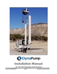
Superior, longer-lasting in-line sealing.<br />
The inert PTFE sleeve completely surrounds the plug. The<br />
sleeve provides a large, circumferential sealing surface from port<br />
to port. Open, closed, or rotating, the seal is assured. No ball or<br />
gate valve can match this sealing power.<br />
Secure sealing with no cold-flow, deformation, or<br />
rotation of the sleeve.<br />
The sleeve is securely nestled in the valve body. High pressure<br />
ribs, top and bottom retention, and 360° port lips all assure<br />
sleeve containment.<br />
No seizing. No sticking.<br />
As the plug rotates, the 360° port lips provide a self-cleaning<br />
action to remove scaling and adhering media.<br />
High pressure sealing ribs<br />
Top retention of sleeve<br />
Sleeve relief area<br />
Bottom retention<br />
of sleeve<br />
360°<br />
lips<br />
No cavities. No contamination.<br />
There are no body cavities where flow<br />
media can accumulate and contaminate<br />
future processing. This cavity-free<br />
design also prevents sticking.<br />
2<br />
© Copyright Xomox Corporation 1965, 2010.<br />
All rights reserved. Xomox ® , Tufline ® . Tufline XP ® and Matryx ®<br />
are registered trademarks of Xomox Corporation.<br />
Xomox XRP is a trademark of Xomox Corporation.
Eliminate unscheduled downtime and maintenance...<br />
plus get greatly extended service life.<br />
Many processors experience<br />
dramatic cost reductions when they<br />
switch from ball and gate valves.<br />
A simple turn of the top adjustment<br />
bolts keeps the sleeve sealing tight<br />
and the valve in service far longer.<br />
Two independent sealing systems provide<br />
double protection against atmospheric<br />
leakage.<br />
Turn the page for details about<br />
this valve’s superior double stem<br />
seal.<br />
Trouble-free sealing is provided by<br />
the large, full-circumferential PTFE<br />
sleeve. No ball or gate valve can<br />
match this sealing capacity.<br />
The PTFE sleeve has a low<br />
coefficient of friction. It acts as<br />
a lubricant. Ease of operation is<br />
assured, even when the valve is left<br />
open or closed for extended periods.<br />
Standard cost and greatly extended<br />
service life assure exceptionally low,<br />
long-term cost-of-ownership.<br />
3
The Tufline ® sleeved plug valve pays for<br />
itself many times over with more up-time<br />
and greatly extended service life.<br />
This product offers a fully adjustable in-line seal and dual<br />
stem seal.<br />
Bolts in the top cover provide quick and easy adjustment.<br />
Adjust out in-line leakage between shutdowns.<br />
Adjust out potential stem leakage.<br />
No ball or gate valve<br />
offers this capability.<br />
Stem Seal 1.<br />
The primary stem seal is around<br />
the circumference of the plug. Flow<br />
media is prevented from reaching<br />
the stem. Stem Seal 2.<br />
There are two<br />
independent<br />
environmental<br />
seals.<br />
You get double<br />
seal protection<br />
at no extra cost.<br />
The secondary backup seal system<br />
provides a wide comprehensive<br />
backup seal along the top edge of<br />
the plug and the stem.<br />
Unmatched stem sealing.<br />
The Tufline standard dual stem<br />
seal is clearly superior to those of<br />
gate valves, ball valves, other plug<br />
valves, and many expensive valves<br />
with extended auxiliary packing.<br />
360° lips.<br />
Port defining lips were developed<br />
and patented by Tufline. The lips<br />
surround the ports.<br />
The lips improve valve performance<br />
and extend service life by:<br />
• Preventing sleeve cold flow and<br />
deformation.<br />
• Eliminating sleeve rotation.<br />
• Breaking up and removing<br />
adhering, scaly deposits from<br />
the outer surface of the plug as it<br />
rotates.<br />
4
Multiport valves.<br />
Tufline Multiport <strong>Sleeved</strong> <strong>Plug</strong><br />
<strong>Valve</strong>s bring economy and a more<br />
compact system design to<br />
thousands of applications.<br />
Bi-directional flow for more<br />
flexibility.<br />
In the diagrams the color indicates<br />
the path of fluid flow. Bi-directional<br />
flow permits more system design<br />
options.<br />
Type<br />
A<br />
Type<br />
AX<br />
0° position<br />
90° position 180° position<br />
Type<br />
C<br />
3-way arrangements.<br />
Only the Type A plug will shut off<br />
the flow. With the Type AX, C, and<br />
D plugs, there is always flow<br />
between the bottom port and one<br />
of the side ports.<br />
Type<br />
C<br />
pos.<br />
1&2<br />
only<br />
Type<br />
C<br />
pos.<br />
2&3<br />
only<br />
Type<br />
D<br />
Type<br />
D<br />
pos.<br />
1&2<br />
only<br />
4-way valves.<br />
For optimum system flexibility, 4-way<br />
multiported valves are available. For<br />
details such as sizes available and<br />
dimensional information visit<br />
www.cranechempharma.com or<br />
contact the factory.<br />
Type<br />
D<br />
pos.<br />
2&3<br />
only<br />
5
Fire-Tested<br />
<strong>Valve</strong>s.<br />
Wedge<br />
Ring<br />
PTFE<br />
Diaphragm<br />
Metal<br />
Diaphragm<br />
Thrust<br />
Collar<br />
Flexible Graphite Cover Seal<br />
API-607 Standards.<br />
Tufline Fire-Tested <strong>Sleeved</strong> <strong>Plug</strong><br />
<strong>Valve</strong>s have been tested in<br />
accordance with API-607 - Fourth<br />
Edition - Section 4.2 - Specifications<br />
For External Leakage. These<br />
valves exceed the sealing requirements<br />
specified in those standards.<br />
A tight external seal was maintained<br />
even after the PTFE sleeve and<br />
sealing parts were totally destroyed<br />
by fire.<br />
Fire tested stem seal.<br />
A metal diaphragm overlays the<br />
PTFE diaphragm. If the PTFE<br />
diaphragm and wedge ring are<br />
destroyed by fire, the metal diaphragm<br />
maintains the seal.<br />
Fire tested cover seal.<br />
In the standard valve, if the PTFE<br />
sleeve and diaphragm are destroyed<br />
by fire, leakage would occur at the<br />
cover joint. The flexible graphite<br />
cover seal prevents this. It is fitted<br />
into a machined counter-bore in the<br />
valve body. The cover bolts compress<br />
the graphite ring between the<br />
valve body and cover. Even if fire<br />
occurs, this seal is maintained.<br />
Vented plug.<br />
In fire-tested valves, the plug is<br />
vented on the upstream side. This<br />
relieves the expansive pressure<br />
caused by the heat of the fire.<br />
<strong>Valve</strong>s with vented plugs are<br />
unidirectional. An arrow stamped<br />
on the valve body indicates the flow<br />
direction.<br />
Sizes: ½” - 6”.<br />
For larger sizes use the Tertiary Top<br />
Seal shown on the next page.<br />
Configurations: 2, 3, and 4-way.<br />
Also partially and fully jacketed.<br />
End connections:<br />
Screwed, flanged, weld.<br />
Pressure ratings:<br />
ANSI 150, 300, and 600.<br />
6
Tertiary Top<br />
Seal <strong>Valve</strong>s.<br />
PTFE diaphragm<br />
PTFE wedge ring<br />
Adjusting<br />
bolt<br />
Cartridge inner ring<br />
Encapsulated, flexible<br />
graphite stem seal<br />
Cartridge<br />
outer ring<br />
<strong>Valve</strong><br />
cover<br />
Metal diaphragm<br />
<strong>Valve</strong><br />
body<br />
PTFE<br />
sleeve<br />
<strong>Plug</strong><br />
Flexible graphite<br />
cover seal<br />
Control fugitive emissions.<br />
This optional top seal package<br />
provides exceptional control of<br />
fugitive emissions. It meets or<br />
exceeds the most stringent current<br />
regulatory requirements.<br />
Triple sealed for extra<br />
protection.<br />
Under normal conditions, there are<br />
three active seals between the flow<br />
media and the atmosphere. Primary<br />
sealing is provided by the interaction<br />
of the plug, sleeve, and body.<br />
Secondary sealing is provided by<br />
the PTFE and metal diaphragms.<br />
Tertiary sealing is provided at the<br />
stem by the encapsulated, flexible<br />
graphite stem seal and at the body/<br />
cover joint by the graphite cover<br />
seal ring.<br />
This simple system assures<br />
stem sealing.<br />
This simple, compact, patented<br />
design harnesses complex dynamic<br />
forces to assure effective sealing to<br />
atmosphere.<br />
The metallic cartridge totally<br />
encapsulates the flexible graphite<br />
tertiary dynamic stem seal.<br />
At its outer edge, the metal diaphragm<br />
overlaps the graphite static<br />
seal ring to reinforce the<br />
tertiary seal at the body-to-cover<br />
joint.<br />
The PTFE wedge ring concentrates<br />
the sealing force of the PTFE diaphragm<br />
radially against the valve<br />
stem for more reliable prevention of<br />
external leakage at this secondary<br />
seal.<br />
API-607 Standards.<br />
Like the fire-tested valve, the Tufline<br />
Tertiary Top Seal <strong>Sleeved</strong> <strong>Plug</strong><br />
valve also exceeds API-607 - Fourth<br />
Edition - Section 4.2 - Specifications<br />
For External Leakage. It is available<br />
in a broader range of sizes than the<br />
standard fire-tested model.<br />
Vented <strong>Plug</strong>.<br />
If this valve is intended for use in a<br />
fire tested application, a vented plug<br />
is required.<br />
Sizes: 1 / 2 inch - 24 inch.<br />
Configurations: 2, 3, and 4-way.<br />
Also partially and fully jacketed.<br />
End connections:<br />
Screwed, flanged,<br />
socket weld, and butt weld.<br />
Pressure ratings:<br />
ANSI 150, 300, and 600.<br />
7
Caged <strong>Plug</strong><br />
<strong>Valve</strong>s.<br />
PTFE sleeve protection.<br />
Tufline <strong>Sleeved</strong> <strong>Plug</strong> <strong>Valve</strong>s can be<br />
furnished with caged plugs. This<br />
provides soft seat protection in<br />
throttling applications and in<br />
services with high pressure drop<br />
through the valve.<br />
Typical applications:<br />
Waste sludge<br />
Calcium carbonate slurry<br />
Alum<br />
Brine<br />
Green liquor<br />
Raw river water<br />
Lime mud<br />
Sulfuric acid with zinc powder<br />
Phosphoric acid slurry<br />
Soda ash<br />
... and many others<br />
The cage is contained within the<br />
plug. It is fixed in place by pins<br />
that are welded in the bottom of the<br />
valve body. Bearings on the cage<br />
provide clearance between the plug<br />
and the cage, so the plug rotates<br />
freely.<br />
Metal-to-metal throttling.<br />
With caged plugs, there is metalto-<br />
metal throttling and metal-to-soft<br />
seat shutoff. In throttling<br />
applications, the cage protects the<br />
seat from erosion by shielding the<br />
soft seat from direct flow<br />
impingement at the valve ports.<br />
High velocity fluids.<br />
With high velocity fluids, the cage<br />
reduces turbulence and cutting<br />
action. The cage provides a more<br />
direct, contoured flow path through<br />
the valve.<br />
Sizes: 1” - 8”.<br />
Materials:<br />
WCB body with CD4MCuN plug and<br />
cage.<br />
CF8M body with CD4MCuN plug<br />
and cage.<br />
(Other materials upon application.<br />
Consult your Tufline Sales<br />
Engineer.)<br />
8
Sampling <strong>Valve</strong>s.<br />
Fluid analysis, equipment<br />
evaluation, problem solving, and<br />
quality control all depend on<br />
convenient sampling.<br />
Safe, simple sampling.<br />
1. <strong>Valve</strong> open - normal flow.<br />
2. As the valve is rotated and<br />
passes the intermediate position,<br />
flow is shut off. A specific<br />
amount of media is trapped<br />
within the plug. There is no<br />
trans-flow.<br />
3. With the valve in the fully closed<br />
position, the trapped sample can<br />
be transferred into an<br />
appropriate container by<br />
operating sample and vent<br />
valving.<br />
<strong>Plug</strong> Cavity Volume - Cubic inches (approximate)<br />
1” 1 1 / 2 ” 2” 2 1 / 2 ” 3” 4” 6”<br />
0.8 1.8 4.5 8.7 8.7 20 58<br />
Infrequent use.<br />
In many applications, sampling<br />
valves are cycled infrequently.<br />
Tufline Sampling <strong>Valve</strong>s provide<br />
excellent operating reliability, even<br />
after being left open for long periods<br />
of time.<br />
Tufline Sampling <strong>Valve</strong>s are<br />
available in a full range of classes,<br />
sizes, and materials. You can also<br />
choose from several levels of<br />
fugitive emissions control.<br />
Gravity Sampling System.<br />
Material drops from the tank or<br />
hopper into the plug cavity. The<br />
modified plug has an opening on<br />
one side only. The plug is rotated<br />
180° and the plug contents are fed<br />
into the gravity or vacuum system<br />
pipe.<br />
The plug rotates 180° to its original<br />
position and refills. The valve can<br />
be manually or automatically<br />
operated. A typical application is<br />
metered injection of a pelletized or<br />
liquid catalyst.<br />
Gravity <strong>Plug</strong> Cavity Volume - Cubic inches (approximate)<br />
1 / 2 ” 1” 1 1 / 2 ” 2” 2 1 / 2 ” 3” 4” 6” 8”<br />
0.2 1.3 3 7 11 11 27 64 142<br />
9
Additional<br />
configurations.<br />
Separate descriptive brochures<br />
and technical data are available<br />
for these valves. Ask your Sales<br />
Engineer for details.<br />
Severe service.<br />
Tufline Severe Service <strong>Valve</strong>s<br />
provide outstanding protection<br />
against external leakage, even with<br />
extreme thermal cycling.<br />
Class 600.<br />
Available in sizes 1/2” thru 24”<br />
in a wide variety of materials.<br />
Multiported also available.<br />
Tufline XP ® <strong>Sleeved</strong> <strong>Plug</strong> <strong>Valve</strong>s<br />
have a patented shrink seal lip.<br />
During thermal cycling, when<br />
fugitive emissions are most likely to<br />
escape, this patented shrink-seal lip<br />
tightens the seal.<br />
To enhance protection against<br />
leakage to atmosphere, the PTFE<br />
chevron rings provide a secondary<br />
(completely redundant) pressureassisted<br />
stem seal.<br />
Live loaded spring washers provide<br />
a constant, uniform pressure on the<br />
packing. This is especially<br />
important during thermal cycling.<br />
To protect the spring washers from<br />
damage and particle intrusion, they<br />
are completely enclosed.<br />
Carbon graphite filled PTFE end<br />
rings prevent extrusion of the PTFE<br />
packing.<br />
The primary external seal is around<br />
the top of the plug.<br />
An optional monitoring/injection port<br />
is also available.<br />
10
Vacuum.<br />
All standard Tufline valves are<br />
satisfactory for vacuum service to as<br />
low as .01 microns of absolute<br />
pressure. However, special cleaning<br />
is required to achieve this rating.<br />
Vacuum ratings have been<br />
established by independent<br />
laboratories by helium leak tests<br />
on mass spectrometers.<br />
XeniTh<br />
TM<br />
600 o F<br />
Chlorine and oxygen.<br />
Cleaning, testing, drying, sealing,<br />
and packaging are all in accordance<br />
with recommended procedures.<br />
High temperature.<br />
XeniTh sleeved plug valve<br />
provide reliable shut-off in<br />
applications with temperatures<br />
up to 600° F.<br />
Bar stock.<br />
Wetted surfaces of these valves are<br />
available in virtually any material<br />
including titanium and zirconium.<br />
Vented plugs.<br />
Tufline valves are available with<br />
vented plugs on the upstream side.<br />
Venting the plug results in a<br />
unidirectional valve.<br />
Full port.<br />
Full round bores, no cavities, and<br />
lips that remove adhering flow<br />
media all make this valve ideal for<br />
slurries, brines, muds, and sewage.<br />
Both 2-way and 3-way valves are<br />
available.<br />
11
PTFE limit<br />
Tufline 600<br />
Pressure-temperature ratings.<br />
The useful range of PTFE sleeved<br />
plug valves is -20°F to +400°F<br />
Tufline-475 sleeve: -20°F to +475°F<br />
Tufline-600 sleeve: -20°F to +600°F<br />
with maximum temperature variation<br />
of 200°F.<br />
Applications beyond these ranges<br />
can be handled effectively but may<br />
require valve adjustments at the<br />
operating temperature.<br />
Material selections are governed by<br />
the limits imposed by ASME B16.34,<br />
1996 edition and B16.34a 1998<br />
edition.<br />
ASME Class 300<br />
CD4MCuN<br />
CF3M/CF8M<br />
INCONEL<br />
WCB<br />
DI<br />
LCB<br />
CF3/CF8<br />
HASTELLOY B&C<br />
NICKEL<br />
MONEL<br />
LCB<br />
CD4MCu N & INCONEL<br />
WCB CF3M/CF8M<br />
CN7M<br />
DI<br />
NICKEL<br />
CF3/CF8<br />
HASTELLOY B&C<br />
MONEL<br />
CN7M<br />
ASME Class 150<br />
Tufline 475<br />
12
Cv factors for valve sizing.<br />
Class 150 & Class 300<br />
3-Way 3-Way 3-Way<br />
Size 2-Way A, AX, C D pos. D pos. 4-Way 5-Way<br />
pos. 0° &180° 90°<br />
1 / 2 9 7 4 5 4 6<br />
3 / 4 9 7 4 5 6 6<br />
1 43 20 11 17 15 27<br />
1 1 / 2 89 40 21 37 30 42<br />
2 172 70 40 47 54 69<br />
3 294 100 54 87 74 120<br />
4 548 175 94 159 150 200<br />
6 1,075 350 210 255 340 390<br />
8 1,591 475 360 450 455 575<br />
10 2,159 650 450 750 610 785<br />
Class 150 Class 300<br />
Operating torques. (Inch-Pounds)<br />
Figures are for 2-Way valves with PTFE sleeves. Consult<br />
factory for torque adjustment factors for other sleeve materials.<br />
Class 150 & 300<br />
Size<br />
Break Seating Running<br />
Torque Torque Torque<br />
Class 150<br />
1 / 2 140 80 70 14 21,000 12,600 10,500<br />
3 / 4 140 80 70 16 36,000 21,000 18,000<br />
1 400 250 200 18 36,000 21,000 18,000<br />
1 1 / 2 800 500 400 20 36,000 21,000 18,000<br />
2 1,100 650 550 24 100,000 60,000 50,000<br />
3 1,200 700 600<br />
4 2,400 1,450 1,200 Class 300<br />
6 5,000 3,000 2,500<br />
12 3,200 965 650 1,000 900 1,160<br />
8 7,800 4,700 3,900<br />
Break Seating Running<br />
Size<br />
Torque Torque Torque<br />
10 14,400 8,600 7,200<br />
12 21,000 12,600 10,500<br />
14x12x14 21,000 12,600 10,500<br />
14x16x14 36,000 21,000 18,000<br />
16 36,000 21,000 18,000<br />
Size 2-Way<br />
Size 2-Way<br />
18 36,000 21,000 18,000<br />
14 3,200 14x12x14 3,200<br />
20 100,000 60,000 50,000<br />
16 5,280 14x16x14 5,280<br />
18 5,600<br />
16 5,600<br />
20 5,900<br />
18 5,900<br />
24 11,000<br />
20 11,000<br />
Size<br />
Break Seating Running<br />
Torque Torque Torque<br />
Screwed end dimensions<br />
Socket Weld<br />
Size D DP<br />
1 / 2 .860 .38<br />
3 / 4 1.070 .50<br />
1 1.335 .50<br />
1 1 / 2 1.920 .50<br />
2 2.411 .63<br />
Screwed End / Class 150 / 2-Way - Figure No. 066* & 3-Way Figure No. 036*<br />
Class 300 / 2-Way - Figure No. 0366 & 3-Way Figure No. 0336<br />
Size L H h H2 B C S J K T E<br />
Weight G Weight<br />
2-Way 3-Way 3-Way<br />
1 / 2 3.25 1.92 1.06 .86 1.43 1.68 .50 .250 .66 5 / 16 -18 6.00 1.5 1.69 1.75<br />
3 / 4 3.25 1.92 1.06 .86 1.43 1.68 .50 .250 .66 5 / 16 -18 6.00 1.5 1.80 1.75<br />
1 4.63 2.50 1.66 .86 1.90 2.21 .63 .438 .32 3 / 8 -16 7.00 4 2.38 5<br />
1 1 / 2 5.50 3.06 2.09 .97 2.33 2.33 .88 .563 .44 3 / 8 -16 8.00 10 2.88 11<br />
2 6.50 3.56 2.56 1.00 3.02 3.02 1.13 .750 .53 7 / 16 -14 9.13 14 3.38 16<br />
*Note: 1/2” thru 2” ANSI Class 150 and Class 300 valves are identical<br />
in fit, form, and function. They are only marked and tagged differently.<br />
13
Dimensions.<br />
Flanged End / Class 150 / 2-Way - Figure No. 067 & 3-Way Figure No. 037<br />
Size L H D T P R N O C S J K E Z CX<br />
* On 8” valves, the two top holes in the flange are tapped for 3 / 4 -10UNC-2B threads.<br />
On 10” and 12” valves, the two top holes in the flange are tapped for 7 / 8 -9UNC-2B threads.<br />
On 14” valves, the two top holes in the flange are tapped for 1-8UNC-2B threads.<br />
On 24” valves, the top six holes in the flange are tapped for 1 1 / 4 -8UNC-2B threads.<br />
† 2 1 / 2 ” valves are machined from 3” castings, but the flanges are machined to 2 1 / 2 ” dimensions.<br />
Dimensions are in inches. Weights are in pounds.<br />
Weight G Weight<br />
2-Way 3-Way 3-Way<br />
1 / 2 4.25 1.92 3.50 .38 1.38 1.75 4 .63 2.38 .50 .250 .66 6.00 - 1.09 2.8 2.75 3.8<br />
3 / 4 4.63 1.92 3.88 .41 1.69 1.94 4 .63 2.75 .50 .250 .66 6.00 - 1.09 3.3 2.88 4.5<br />
1 5.00 2.50 4.25 .44 2.00 2.13 4 .63 3.13 .63 .438 .32 7.00 .53 1.38 6.5 3.50 9<br />
1 1 / 2 6.50 3.06 5.00 .56 2.88 2.50 4 .63 3.88 .88 .563 .44 8.00 .59 1.56 13 4.13 17<br />
2 7.00 3.56 6.00 .63 3.63 3.00 4 .75 4.75 1.13 .750 .53 9.13 .78 2.00 20 4.50 26<br />
2 1 / 2 † 8.00 4.13 7.50 .75 4.13 3.75 4 .75 5.50 1.13 .750 .53 10.13 .78 2.00 31 5.13 42<br />
3 8.00 4.13 7.50 .75 5.00 3.75 4 .75 6.00 1.13 .750 .53 10.13 .78 2.00 31 5.13 42<br />
4 9.00 5.22 9.00 .94 6.19 4.63 8 .75 7.50 1.25 .875 .78 22.00 .90 2.50 54 6.00 69<br />
6 10.50 7.35 11.00 1.00 8.50 5.50 8 .88 9.50 2.00 1.398 1.00 25.00 - 3.06 95 7.50 119<br />
8 11.50 9.32 13.50 1.13 10.63 6.75 8 .88* 11.75 2.00 1.398 1.00 28.00 - 4.12 175 9.00 214<br />
10 13.00 10.81 16.00 1.19 12.75 8.00 12 1.00* 14.25 2.50 1.673 1.00 29.00 - 4.50 260 11.00 331<br />
12 14.00 11.81 19.00 1.25 15.00 9.50 12 1.00* 17.00 3.00 1.968 1.00 35.00 - 5.31 355 - -<br />
14 15.00 11.75 21.00 1.38 16.25 10.50 12 1.13* 18.75 2.97 1.968 .995 N/A - 5.31 430 - -<br />
16 30.00 14.96 23.50 2.12 18.50 11.50 16 1.13 21.25 3.94 2.00 1.575 N/A - N/A 925 - -<br />
18 33.00 14.96 25.50 2.25 21.00 12.75 16 1.25 22.75 3.94 2.00 1.575 N/A - N/A 1,005 - -<br />
20 36.00 14.96 27.50 2.38 23.00 14.00 20 1.25 25.00 3.937 2.00 1.575 N/A - N/A 1,200 - -<br />
24 39.00 20.48 32.00 2.50 27.25 16.13 20 1.38* 29.50 6.00 4.00 2.000 N/A - N/A 2,500 - -<br />
14
Flanged End / Class 300 / 2-Way - Figure No. 0367 & 3-Way Figure No. 0337<br />
Size L H D T P R N O C S J K E Z CX<br />
Weight G Weight<br />
2-Way 3-Way 3-Way<br />
1 / 2 5.50 1.92 3.75 .56 1.38 1.88 4 .63 2.63 .50 .250 .66 6.00 - 1.09 6 2.88 8<br />
3 / 4 6.00 1.92 4.63 .63 1.69 2.31 4 .75 3.25 .50 .250 .66 6.00 - 1.09 9 3.00 12<br />
1 6.50 2.50 4.88 .69 2.00 2.44 4 .75 3.50 .63 .438 .32 7.00 .53 1.38 11 3.75 15<br />
1 1 / 2 7.50 3.06 6.13 .81 2.88 3.06 4 .88 4.50 .88 .563 .44 8.00 .59 1.56 21 4.38 29<br />
2 8.50 3.56 6.50 .88 3.63 3.25 8 .75 5.00 1.13 .750 .53 9.13 .78 2.00 28 4.75 37<br />
2 1 / 2 † 11.13 4.13 8.25 1.13 4.13 4.13 8 .88 5.88 1.13 .750 .53 10.13 .78 2.00 38 5.56 53<br />
3 11.13 4.13 8.25 1.13 5.00 4.13 8 .88 6.63 1.13 .750 .53 10.13 .78 2.00 38 5.56 53<br />
4 12.00 5.22 10.00 1.25 6.19 5.13 8 .88 7.88 1.25 .875 .78 22.00 .90 2.50 80 6.75 105<br />
6 15.88 7.35 12.50 1.44 8.50 6.25 12 .88 10.63 2.00 1.398 1.00 25.00 - 3.06 165 8.50 207<br />
8 16.50 9.32 15.00 1.63 10.63 7.50 12 1.00 13.00 2.00 1.398 1.00 28.00 - 4.12 267 10.00 334<br />
10 18.00 10.81 17.50 1.88 12.75 8.75 l6 1.13 15.25 2.50 1.673 1.00 29.00 - 4.50 395 12.00 470<br />
12 19.75 11.81 20.50 2.00 15.00 10.25 16 1.25 17.75 3.00 1.968 1.00 35.00 - 5.31 540 - -<br />
14 30.00 14.96 23.00 2.12 16.25 11.50 20 1.25* 20.25 3.937 2.00 1.575 N/A - N/A 925 - -<br />
16 33.00 14.96 25.50 2.25 18.50 12.75 20 1.38 22.50 3.937 2.00 1.575 N/A - N/A 1,005 - -<br />
18 36.00 14.96 28.00 2.38 21.00 14.00 24 1.38 24.75 3.937 2.00 1.575 N/A - N/A 1,200 - -<br />
20 39.00 20.48 32.00 2.50 23.00 16.13 24 1.38 27.00 6.00 4.00 2.00 N/A - N/A 2,500 -<br />
* On 14” valves, the two top holes in the flanges are tapped for 1-8UNC-2B threads.<br />
† 2 1 / 2 ” valves are machined from 3” castings, but the flanges are machined to 2 1 / 2 ” dimensions.<br />
Dimensions are in inches. Weights are in pounds.<br />
Wrench & Enclosed Gear Operator Dimensions.<br />
These operator dimensions apply to all flange types and all<br />
multiport valves.<br />
Size M B Y<br />
1 / 2 - 4.00 6.38<br />
3 / 4 - 4.00 6.38<br />
1 3.81 2.88 8.75<br />
1 1 / 2 4.56 3.63 12.50<br />
2 5.13 4.00 18.00<br />
2 1 / 2 5.69 4.63 24.00<br />
3 5.69 4.63 24.00<br />
4 7.06 5.75 30.00<br />
Size F G U V<br />
4 8.75 6.00 2.06 8.00<br />
6 11.50 9.00 2.62 10.38<br />
8 13.50 9.00 2.62 10.38<br />
10 15.25 12.00 3.53 12.31<br />
12 16.25 15.00 4.88 15.88<br />
14 21.66 15.00 5.38 16.90<br />
16 21.66 12.00 5.12 17.66<br />
18 21.66 12.00 5.12 17.66<br />
20 32.92 15.75 16.97 24.00<br />
24 32.92 15.75 16.97 24.00<br />
15
Manual<br />
Operators.<br />
A wide variety of handle and gear<br />
operators are available.<br />
You can choose from chain<br />
wrenches, T-wrenches, chain<br />
wheels, and tandem adapters.<br />
Talk with your Tufline Sales<br />
Engineer about your specific<br />
requirements, sizing, and how to<br />
order.<br />
CRANE ChemPharma, Xomox Actuators –<br />
Automation Accessories<br />
CRANE ChemPharma,<br />
Xomox XRP Actuators.<br />
The unique features of the CRANE<br />
ChemPharma, Xomox XRP<br />
Pneumatic Rack & Pinion Actuators<br />
include:<br />
• A balanced pinion which does not<br />
require an external retaining clip<br />
to prevent the pinion from blowing<br />
out.<br />
• Individual single point adjustment<br />
for both the CW and CCW<br />
directions.<br />
• 98 degrees of total travel on the<br />
most popular sizes.<br />
• Vertically aligned air passages<br />
allow increased air flow<br />
minimizing cycle time.<br />
Locking Devices.<br />
CRANE ChemPharma,<br />
Xomox Limit Switches.<br />
A wide variety of switching options<br />
and other automation accessories<br />
are available.<br />
16<br />
Specify whether the valve is to be<br />
locked open, closed, or both.<br />
(The lock is not supplied.)<br />
Matryx ® Vane Actuators.<br />
Matryx Vane Actuators provide the<br />
most reliable and efficient remote<br />
control of any type of rotary operation.<br />
They are used for ball, plug,<br />
and butterfly valves as well as other<br />
mechanisms such as dampers,<br />
switches, and safety devices. They<br />
are available up to 30,000 in-lbs of<br />
torque.
Actuator mounting hole configurations.<br />
Full dimensions for valve and actuator assemblies are available.<br />
Class 150<br />
4 hole pattern 2 hole pattern<br />
Size A AY W X A W X<br />
1/ 2 - - - - 3.62 5/ 16 -18 .47<br />
3/ 4 - - - - 3.75 5/ 16 -18 .47<br />
1 4.19 1.75 5/ 16 -18 .38 - - -<br />
1 1 / 2 5.75 1.75 5/ 16 -18 .47 - - -<br />
2 6.31 2.25 5/ 16 -18 .47 - - -<br />
2 1 / 2 7.13 3.50 3/ 8 -16 .56 - - -<br />
3 7.13 3.50 3/ 8 -16 .56 - - -<br />
4 8.00 4.00 7/ 16 -14 .63 - - -<br />
6 9.44 4.00 7/ 16 -14 .63 - - -<br />
8 10.19 6.00 1/ 2 -13 .63 - - -<br />
10 11.56 6.00 1/ 2 -13 .63 - - -<br />
12 12.53 6.00 1/ 2 -13 .63 - - -<br />
14 13.750 6.00 1/ 2 -13 .63 - - -<br />
16 27.812 8.00 5/ 8 -11 1.00 - - -<br />
18 30.688 8.00 5/ 8 -11 1.00 - - -<br />
20 33.56 8.00 5/ 8 -11 1.00 - - -<br />
24 36.25 11.50 1.00-8 1.50 - - -<br />
Class 300<br />
4 hole pattern 2 hole pattern<br />
Size A AY W X A W X<br />
1/ 2 - - - - 4.38 5/ 16 -18 .47<br />
3/ 4 - - - - 4.38 5/ 16 -18 .47<br />
1 5.75 1.75 5/ 16 -18 .38 - - -<br />
1 1 / 2 6.63 1.75 5/ 16 -18 .47 - - -<br />
2 7.56 2.25 5/ 16 -18 .47 - - -<br />
2 1 / 2 9.94 3.50 3/ 8 -16 .56 - - -<br />
3 9.94 3.50 3/ 8 -16 .56 - - -<br />
4 10.69 4.00 7/ 16 -14 .63 - - -<br />
6 14.00 4.00 7/ 16 -14 .63 - - -<br />
8 14.63 6.00 1/ 2 -13 .63 - - -<br />
10 15.69 6.00 1/ 2 -13 .63 - - -<br />
12 17.38 6.00 1/ 2 -13 .63 - - -<br />
14 27.812 8.00 5/ 8 -11 1.00 - - -<br />
16 30.688 8.00 5/ 8 -11 1.00 - - -<br />
18 33.563 8.00 5/ 8 -11 1.00 - - -<br />
20 36.25 11.50 1.00-8 1.50 - - -<br />
Dimensions are in inches.<br />
17
Quick Reference Selection Table.<br />
The table below provides a brief overview of the most commonly specified valves. When ordering, be sure to specify<br />
all options including body, plug, and sleeve materials.<br />
No. of Type* ANSI Size<br />
Figure<br />
Operator<br />
Ports Class Range Number<br />
Notes<br />
Screwed End 150 1/ 2 -2 066<br />
300 Wrench 0366<br />
150 1/ 2 -4 067<br />
Flanged End 4-24 Enclosed Gear 067EG<br />
300 1/ 2 -4 Wrench 0367<br />
2-way Tufline <strong>Sleeved</strong><br />
<strong>Plug</strong> <strong>Valve</strong>s provide<br />
tight shutoff from high<br />
vacuum through rated<br />
pressure at temperatures<br />
from -20°F to 600°F<br />
4-24 Enclosed Gear 0367EG<br />
2 150 1-4 Wrench 067PJ<br />
Partial Jacket 4-12 Enclosed Gear 067PJ-EG<br />
300 1-4 Wrench 0367PJ<br />
4-12 Enclosed Gear 0367PJ-EG<br />
150 2x1x2-6x4x6 Wrench 067FJ<br />
Full Jacket 6x4x6-12x10x12 Enclosed Gear 067FJ-EG<br />
300 2x1x2-6x4x6 Wrench 0367FJ<br />
Standard jacketed valves<br />
are available in carbon steel<br />
or CF8M stainless steel.<br />
All jackets are rated at 235<br />
psi at 400°F.<br />
Full jacketed valves have<br />
over-sized flanges.<br />
6x4x6-12x10x12 Enclosed Gear 0367FJ-EG<br />
Screwed End 150 1/ 2 -2 036<br />
300 1/ 2 -2 Wrench 0336<br />
150 1/ 2 -4 037<br />
Flanged End 4-12 Enclosed Gear 037EG<br />
3 300 1/ 2 -4 Wrench 0337<br />
4-12 Enclosed Gear 0337EG<br />
150 1-4 Wrench 037PJ<br />
When ordering 3-way<br />
valves, be sure to include<br />
the port configuration.<br />
Refer to page 5.<br />
Partial Jacket 4-8 Enclosed Gear 037PJ-EG<br />
300 1-4 Wrench 0337PJ<br />
4-8 Enclosed Gear 0337PJ-EG<br />
Screwed End 1/ 2 -2 Wrench 046<br />
4 Flanged End 150 1/ 2 -4 047<br />
Flanged End 6-12 Enclosed Gear 047-EG<br />
Bodies are available in<br />
carbon steel or CF8M<br />
stainless steel. Standard<br />
pressure/temperature ratings<br />
apply, with the exception<br />
that pressure drop should<br />
not exceed 170 psi at 100°F<br />
when switching.<br />
* Socket weld and butt weld end valve information is available in a separate catalog.<br />
18
Materials.<br />
The following are ASTM designations for materials<br />
listed elsewhere in this catalog.<br />
Carbon steel.................. ASTM A216 WCB<br />
302 stainless steel........ ASTM A240 Type 302<br />
304 stainless steel........ ASTM A240 Type 304<br />
How to specify<br />
Size<br />
Figure No.<br />
Option<br />
Body<br />
<strong>Plug</strong><br />
Sleeve<br />
Operator<br />
1” - 066 - FT - 6 - 6 - P1 - W - C<br />
Service<br />
304 stainless steel........ ASTM A351 CF8<br />
304L stainless steel...... ASTM A351 CF3<br />
316 stainless steel........ ASTM A351 CF8M<br />
316L stainless steel...... ASTM A351 CF3M<br />
Alloy 20......................... ASTM A351 CN7M<br />
Bronze........................... ASTM B61<br />
CD4MCuN..................... ASTM A995 CD4MCuN<br />
Ductile Iron.................... ASTM A395<br />
Hastelloy B.................... ASTM A494 N7M<br />
Hastelloy C.................... ASTM A494 CW6M<br />
Inconel.......................... ASTM A494 CY40<br />
Nickel............................ ASTM A494 CZ-100<br />
Monel............................ ASTM A494 M30-C (Body)<br />
or ASTM A494 M351 (<strong>Plug</strong>)<br />
Ni-Al Bronze.................. ASTM B148 Gr.958<br />
Titanium........................ ASTM B367 Gr. C-3<br />
Zirconium...................... ASTM B752 Gr. 702<br />
Other ferrous and non-ferrous materials are available<br />
upon application.<br />
Size &<br />
Figure No.<br />
See Quick Reference<br />
Selection Table on the<br />
previous page<br />
Options<br />
Fire Tested.............. FT<br />
Tertiary Top Seal....TS<br />
Cage Control........CCV<br />
Extended Packing...XP<br />
Partial Jacket.......... PJ<br />
Full Jacket................FJ<br />
Port Arrangements<br />
for 3-Way valves<br />
(See page 6)<br />
..............A, AX, C, or D<br />
<strong>Valve</strong> specifications<br />
may include multiple<br />
options.<br />
Body<br />
Alloy 20......................0<br />
Ductile Iron.................1<br />
Carbon Steel..............2<br />
Monel.........................3<br />
Nickel.........................5<br />
CF8M.........................6<br />
Hastelloy B.................8<br />
Hastelloy C.................9<br />
CD4MCuN................27<br />
lnconel......................40<br />
Other (Specify).......... X<br />
* Specify actuator type and<br />
available air supply.<br />
** Consult your Xomox Sales<br />
Engineer for a wide variety of<br />
other available service options.<br />
Service<br />
Chlorine................C<br />
Oxygen................ O<br />
Vacuum................V<br />
General<br />
Service.......... Blank<br />
Other**.................X<br />
Operator<br />
Less Operator......N<br />
Wrench................W<br />
Wrench with<br />
locking device.. WY<br />
Gear.................... G<br />
Gear with<br />
locking device... GZ<br />
Actuator*..............A<br />
Sleeve<br />
PTFE..................P1<br />
15% RPTFE.......P2<br />
25% RPTFE.......P3<br />
PFA....................P6<br />
Xomox-7.............P7<br />
UHMWPE...........P8<br />
Tufline-475.......P16<br />
Tufline-600.......P20<br />
Other<br />
(Specify)............ PX<br />
<strong>Plug</strong><br />
Alloy 20................ 0<br />
Monel................... 3<br />
304SS.................. 4<br />
Nickel................... 5<br />
CF8M................... 6<br />
Hastelloy B........... 8<br />
Hastelloy C........... 9<br />
CD4MCuN.......... 27<br />
Inconel............... 40<br />
Other (Specify).....X<br />
19
CRANE ChemPharma Flow Solutions<br />
XOMOX Headquarters<br />
4444 Cooper Road,<br />
Cincinnati, OH 45242, U.S.A.<br />
Tel.: (513) 745-6000<br />
Fax: (513) 745-6086<br />
XOMOX International GmbH & Co. OHG<br />
Von-Behring-Straße 15,<br />
D-88131 Lindau/Bodensee<br />
Tel.: (49) 8382-702-0<br />
Fax. (49) 8382-702-144<br />
brands you trust.<br />
www.flowoffluids.com<br />
CRANE ChemPharma Flow Solutions Include: Pipe - <strong>Valve</strong>s - Fitting - Actuators - Pumps<br />
CP-XOMOX-SPV-BU-EN-CI-5/10-PN329703<br />
Crane Co., and its subsidiaries cannot accept responsibility for possible errors in catalogues, brochures, other printed materials, and website<br />
information. Crane Co. reserves the right to alter its products without notice, including products already on order provided that such<br />
alteration can be made without changes being necessary in specifications already agreed. All trademarks in this material are property of<br />
the Crane Co. or its subsidiaries. The Crane and Crane brands logotype (Xomox ® , Saunders ® , Resistoflex ® , Resistopure, PSI ® , DEPA ® , ELRO ® ,<br />
REVO ® ) are registered trademarks of Crane Co. All rights reserved.<br />
© 2010 CRANE ChemPharma Flow Solutions, www.cranechempharma.com