STEAM AIR MAKE-UP - Aerovent
STEAM AIR MAKE-UP - Aerovent
STEAM AIR MAKE-UP - Aerovent

You also want an ePaper? Increase the reach of your titles
YUMPU automatically turns print PDFs into web optimized ePapers that Google loves.
®<br />
The Industrial Choice.<br />
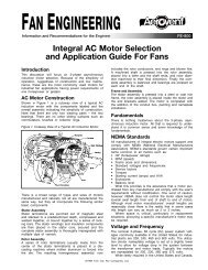
<strong>STEAM</strong> <strong>AIR</strong> <strong>MAKE</strong>-<strong>UP</strong><br />
Axial Flow & Centrifugal<br />
BULLETIN 856 December 2006
Controls<br />
Control Option MA<br />
NEMA 4 enclosure with disconnect switch, motor starter, transformer, relay, terminal strip, low limit thermostat,<br />
shutter motor end switch mounted and wired with connection points for additional controls as may be furnished<br />
by others.<br />
Control Option MB (to be used with MA)<br />
Temperature controller, modulating valve-motor-linkage, remote operating station for field mounting and<br />
interconnection.<br />
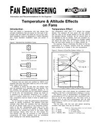
Outlet Temperature Control (OTC)<br />
The OTC system is designed to provide a constant average temperature at the discharge of the air make-up<br />
unit. The temperature setting is manually adjustable from the operating control station, which is usually mounted<br />
at floor level. This station contains the "on-off" control, indicator lamp, and the temperature setting control. The<br />
discharge temperature is regulated and maintained by a motor-driven modulating valve. The motor is actuated<br />
by electronic sensing devices and an amplifier system, and the valve regulates the flow of steam into the coil.<br />
The electronic modulating system is the best available. It is extremely stable and has no tendency to override<br />
on start-up. It will quickly bring the modulating valve to a position of equilibrium and accurately maintain<br />
the balance between heat load demand and steam flow.<br />
Remote Operating Station with outlet temperature control<br />
(OTC) selector, on-off switch, and indicator lamp at<br />
floor level<br />
Standardized control panel — NEMA 4<br />
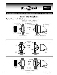
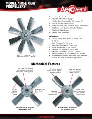
Steam Distributing Tube Coil<br />
Supply and return connections are at the same end.<br />
This allows free expansion of the core without transmitting<br />
stresses to the tubes, casing, or tube header<br />
joints. This design provide good temperature distribution<br />
and a maximum of freeze protection. The outer<br />
tube is 5 ∕8" in diameter and the inner tube is dieformed<br />
to be self-centering with steam jets designed<br />
to propel the condensate toward the return header.<br />
In operation, the steam enters the supply section<br />
at the center of the header marked “A”. It passes to<br />
the inner distributing tubes and issues evenly from<br />
jets throughout the tube length. The condensate is<br />
formed in the outer tube and runs down into the<br />
upper half of the header and then to the return line<br />
connection at “B”. Coupling “C” is for the vacuum<br />
breaker.<br />
A<br />
B<br />
C<br />
2 <strong>Aerovent</strong> Bulletin 856
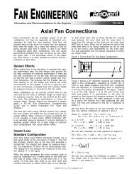
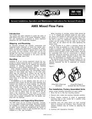
Accessories<br />
Inlet Hood<br />
With turning vanes as shown or fewer turning vanes<br />
for use with vee bank filter section. Available for all<br />
units.<br />
Inlet or Discharge<br />
Elbows With<br />
Turning Vanes<br />
Inlet elbows for use with<br />
propeller units. Discharge<br />
elbows fit the propeller<br />
units and are adaptable<br />
to others.<br />
Inlet hood<br />
Directional Discharge Grille<br />
Provides for four-way adjustment of airflow. Cabinet<br />
is lined with acoustic material. It is usually used with<br />
propeller type units.<br />
Filter Section<br />
There are three types available:<br />
vee bank, Roll-O-Matic,<br />
or flat-bank design. The<br />
standard filter is a disposable<br />
type with washable available<br />
as an option.<br />
Vee bank filter<br />
section<br />
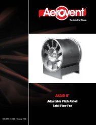
Air Distributor<br />
Features four directional discharge grilles.<br />
Vibration Eliminators<br />
Available for use with all type units. Rubber-in-shear<br />
or spring.<br />
Bird Screen<br />
Available for use on all type units.<br />
Service Platform<br />
For convenient access to motor and control enclosure,<br />
a sturdily-built service platform is optional for<br />
all installations.<br />
Air distributor<br />
Additional Options<br />
The following is a condensed list of additional options. Please contact your <strong>Aerovent</strong> representative with specific<br />
requirements not shown.<br />
• Water or electric heating coil in lieu of steam<br />
• Face and bypass configuration<br />
• Integral face and bypass coil<br />
• Chilled water or DX cooling section<br />
• Process heating applications<br />
• Recirculation mixing box<br />
• High efficiency filtration<br />
• Evaporative air cooler section<br />
• Internal fan vibration isolation<br />
• Galvanized, aluminum or stainless steel construction<br />
• Special paints/coatings<br />
• Double wall insulated construction<br />
• Vertical mounting configuration<br />
• PLC controls<br />
• Variable frequency drive or 2-speed operation<br />
• Custom unit design or controls to meet customer<br />
needs<br />
3 <strong>Aerovent</strong> Bulletin 856
Performance Data — Propeller Fan<br />
Unit includes fan, coil, vacuum breaker and motorized<br />
shutter — assembled.<br />
Discharge grille is optional (see page 3).<br />
For control options, see page 2.<br />
Propeller Fan<br />
BTU/HR<br />
CATALOG EXT. FAN FAN MOTOR TEMP.<br />
CFM<br />
(5 PSI<br />
NUMBER<br />
SP SIZE RPM HP RISE<br />
<strong>STEAM</strong>)<br />
S30L422-1052-1 7,000 0 30 1052 1 0-84 711,000<br />
S30L422-1238-1.5 7,000 1<br />
⁄4 30 1238 1 1 ⁄2 0-84 711,000<br />
S30L422-1419-3 7,000 1<br />
⁄2 30 1419 3 0-84 711,000<br />
S30L422-1403-3 10,000 0 30 1403 3 0-74 1,070,000<br />
S30L422-1536-3 10,000 1<br />
⁄4 30 1536 3 0-74 1,070,000<br />
S30L422-1668-5 10,000 1<br />
⁄2 30 1668 5 0-74 1,070,000<br />
S36L422-982-2 11,250 0 36 982 2 0-84 918,000<br />
S36L422-1106-3 11,250 1<br />
⁄4 36 1106 3 0-84 918,000<br />
S36L422-1225-5 11,250 1<br />
⁄2 36 1225 5 0-84 918,000<br />
S36L422-1255-5 15,000 0 36 1255 5 0-74 1,225,000<br />
S36L422-1351-5 15,000 1<br />
⁄4 36 1351 5 0-74 1,225,000<br />
S36L422-1444-7.5 15,000 1<br />
⁄2 36 1444 7 1 ⁄2 0-74 1,225,000<br />
S42L422-788-2 15,000 0 42 788 2 0-84 1,520,000<br />
S42L422-899-3 15,000 1<br />
⁄4 42 899 3 0-84 1,520,000<br />
S42L422-1004-5 15,000 1<br />
⁄2 42 1004 5 0-84 1,520,000<br />
S42L422-994-5 20,000 0 42 994 5 0-74 1,637,000<br />
S42L422-1081-5 20,000 1<br />
⁄4 42 1008 5 0-74 1,637,000<br />
S42L422-1164-7.5 20,000 1<br />
⁄2 42 1164 7 1 ⁄2 0-74 1,637,000<br />
S48L422-759-5 18,750 0 48 759 5 0-84 1,766,000<br />
S48L422-854-5 18,750 1<br />
⁄4 48 854 5 0-84 1,766,000<br />
S48L422-946-7.5 18,750 1<br />
⁄2 48 946 7 1 ⁄2 0-84 1,766,000<br />
S48L422-987-7.5 25,000 0 48 987 7 1 ⁄2 0-74 2,100,000<br />
S48L422-1062-10 25,000 1<br />
⁄4 48 1062 10 0-74 2,100,000<br />
S48L422-1133-10 25,000 1<br />
⁄2 48 1133 10 0-74 2,100,000<br />
S54L422-650-5 26,250 0 54 650 5 0-84 2,500,000<br />
S54L422-732-5 26,250 1<br />
⁄4 54 732 5 0-84 2,500,000<br />
S54L422-811-7.5 26,250 1<br />
⁄2 54 811 7 1 ⁄2 0-84 2,500,000<br />
S54L422-827-7.5 26,250 0 54 827 7 1 ⁄2 0-74 3,000,000<br />
S54L422-892-10 26,250 1<br />
⁄4 54 892 10 0-74 3,000,000<br />
S54L422-954-15 26,250 1<br />
⁄2 54 954 15 0-74 3,000,000<br />
S60L422-597-7.5 33,750 0 60 597 7 1 ⁄2 0-84 3,200,000<br />
S60L422-670-7.5 33,750 1<br />
⁄4 60 670 7 1 ⁄2 0-84 3,200,000<br />
S60L422-738-10 33,750 1<br />
⁄2 60 738 10 0-84 3,200,000<br />
S60L422-785-15 45,000 0 60 785 15 0-74 3,700,000<br />
S60L422-841-15 45,000 1<br />
⁄4 60 841 15 0-74 3,700,000<br />
S60L422-894-15 45,000 1<br />
⁄2 60 894 15 0-74 3,700,000<br />
S72L422-478-7.5 45,000 0 72 478 7 1 ⁄2 0-84 4,300,000<br />
S72L422-542-10 45,000 1<br />
⁄4 72 542 10 0-84 4,300,000<br />
S72L422-602-15 45,000 1<br />
⁄2 72 602 15 0-84 4,300,000<br />
S72L422-607-15 60,000 0 72 607 15 0-74 5,000,000<br />
S72L422-657-15 60,000 1<br />
⁄4 72 657 15 0-74 5,000,000<br />
S72L422-705-20 60,000 1<br />
⁄2 72 705 20 0-74 5,000,000<br />
NOTE: Add 1/4" when ordering with filters. BHP does not include belt drive losses.<br />
4 <strong>Aerovent</strong> Bulletin 856
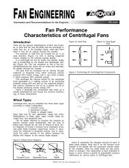
Dimensional Data — Propeller Fan<br />
7/16" x 1" SLOTS SPACED 8 5/8" CL<br />
TO CL FROM CL (TYP. 4 SIDES)<br />
B SQ.<br />
INSIDE<br />
E<br />
L<br />
D<br />
CONTROL PANEL ENCLOSURE<br />
20"x20"x6"<br />
1<br />
20x24<br />
ACCESS<br />
DOOR ON<br />
OPPOSITE<br />
CONTROL<br />
SIDE<br />
P SQ.<br />
2"<br />
A SQ.<br />
M<br />
V<br />
2"<br />
P/2<br />
C<br />
W SQ.<br />
INSIDE<br />
G<br />
12 GA. HOUSING<br />
MOTOR OPERATED SHUTTER<br />
K + - 1/4<br />
G <strong>STEAM</strong> COIL<br />
SIZES 30 THRU 48 - 3"-4.1# CHANNEL W/(4) 7/16" DIA. MTG. HOLES,<br />
SIZES 54 THRU 72 - 5"-9.0# CHANNEL W/(4) 9/16" DIA. MTG. HOLES,<br />
RETURN<br />
S<strong>UP</strong>PLY<br />
SIZE A B C D E G K L M P R V W<br />
30 39 1 ⁄2 36 1 ⁄8 21 3 ⁄16 53 1 1 ⁄2 40 3 ⁄4 37 3 ⁄8 39 47 38<br />
13<br />
⁄16 51 36<br />
36 45 1 ⁄2 42 1 ⁄8 24 3 ⁄16 53 1 1 ⁄2 46 3 ⁄4 37 3 ⁄8 39 57 44<br />
13<br />
⁄16 61 42<br />
42 51 1 ⁄2 48 1 ⁄8 27 3 ⁄16 53 1 1 ⁄2 52 3 ⁄4 37 3 ⁄8 39 63 50<br />
13<br />
⁄16 67 48<br />
48 57 1 ⁄2 54 1 ⁄8 30 3 ⁄16 59 1 1 ⁄2 58 3 ⁄4 43 3 ⁄8 45 71 56<br />
13<br />
⁄16 75 54<br />
54 71 1 ⁄2 68 1 ⁄8 39 3 ⁄16 66 1 ⁄2 2 75 1 ⁄4 50 1 ⁄4 52 1 ⁄2 86 70 1 1 ⁄8 90 68<br />
60 78 1 ⁄2 75 1 ⁄8 42 11 ⁄16 66 1 ⁄2 2 82 1 ⁄4 50 1 ⁄4 52 1 ⁄2 92 77 1 1 ⁄8 96 75<br />
72 91 1 ⁄2 88 1 ⁄8 49 3 ⁄16 66 1 ⁄2 2 95 1 ⁄4 50 1 ⁄4 52 1 ⁄2 108 90 1 1 ⁄8 112 88<br />
Dimensions are not to be used for construction.<br />
NOTES:<br />
Panel location may vary from indicated position on various sizes and size of enclosure may change for special modifications.<br />
Welded construction with internal reinforcing.<br />
NEMA 12 control panel enclosure.<br />
Liquid-tight conduit.<br />
• Propeller is 4, 6 or 7 blade as required per catalog no.<br />
7/16 Dia. Holes<br />
Match Drilled to AMU Unit<br />
A<br />
E B<br />
E E<br />
J<br />
20x25x2 High Velocity Disposable Filters.<br />
Number of Filters Varies With CFM Requirements.<br />
(Washable Filters Are Optional.)<br />
Airflow<br />
D<br />
G<br />
C<br />
(See<br />
Note 2)<br />
M Sq.<br />
P Sq.<br />
E<br />
F<br />
W<br />
2 X<br />
Y<br />
(H) Dia. Hole<br />
SIZE A B C D E F G H J M P W X Y GA.<br />
30 52 5 ⁄8 49 1 ⁄2 21 1 ⁄8 42 1 ⁄8 1 9 ⁄16<br />
36 62 1 ⁄8 59 24 1 ⁄8 68 1 ⁄8 1 9 ⁄16<br />
42 62 1 ⁄8 59 27 3 ⁄16 74 1 9 ⁄16<br />
48 81 7 ⁄8 78 5 ⁄8 30 3 ⁄16 80 1 5 ⁄8<br />
13<br />
⁄16 46 3 ⁄4<br />
13<br />
⁄16 72 3 ⁄4<br />
13<br />
⁄16 78 5 ⁄8<br />
13<br />
⁄16 84 3 ⁄4<br />
54 82 7 ⁄8 78 5 ⁄8 39 3 ⁄16 94 1 ⁄2 2 1 ⁄8 1 1 ⁄8 101 3 ⁄4<br />
60 102 1 ⁄2 98 1 ⁄4 42 11 ⁄16 101 1 ⁄2 2 1 ⁄8 1 1 ⁄8 108 3 ⁄4<br />
7<br />
⁄16 33 36 1 ⁄8 38 3 8 3 ⁄4 57 3 ⁄4 14<br />
7<br />
⁄16 35 42 1 ⁄8 44 3 10 1 ⁄2 69 1 ⁄2 14<br />
7<br />
⁄16 35 48 1 ⁄8 50 1 ⁄8 3 7 1 ⁄2 72 1 ⁄2 14<br />
7<br />
⁄16 35 54 1 ⁄8 56 1 ⁄8 3 14 3 ⁄8 87 3 ⁄8 12<br />
9<br />
⁄16 35 68 1 ⁄8 70 5 ⁄8 5 7 3 ⁄8 95 3 ⁄8 12<br />
9<br />
⁄16 35 75 1 ⁄8 77 5 ⁄8 5 13 11 ⁄16 107 11 ⁄16 12<br />
72 122 3 ⁄4 118 1 ⁄2 49 3 ⁄16 114 3 ⁄4 2 1 ⁄8 1 1 ⁄8 122 9<br />
⁄16 35 88 1 ⁄8 90 5 ⁄8 5 17 3 ⁄16 127 3 ⁄16 12<br />
Dimensions are not to be used for construction.<br />
5 <strong>Aerovent</strong> Bulletin 856
Performance Data — DW Centrifugal Fan<br />
Unit includes fan, coil, vacuum breaker and motorized<br />
shutter — assembled.<br />
For control options, see page 2.<br />
FC-DW Centrifugal (Forward Curved Blade)<br />
CATALOG<br />
NUMBER<br />
SCDW-400-FC<br />
SCDW-560-FC<br />
SCDW-630-FC<br />
SCDW-710-FC<br />
SCDW-800-FC<br />
SCDW-900-FC<br />
SCDW-1000-FC<br />
CFM<br />
TEMP.<br />
RISE<br />
BTU/HR<br />
EXTERNAL STATIC PRESSURE<br />
(5 PSI) OV 0" 1/2" 1" 1 1 ⁄2" 2"<br />
<strong>STEAM</strong>) RPM BHP RPM BHP RPM BHP RPM BHP RPM BHP<br />
3,750 0-84 343,000 1678 438 0.47 635 0.90 805 1.42 961 2.04 1110 2.76<br />
5,000 0-84 458,000 2238 557 1.04 709 1.54 848 2.13 977 2.80 1102 3.55<br />
7,500 0-84 687,000 1754 326 0.96 450 1.69 563 2.67 666 3.82 758 5.05<br />
10,000 0-84 915,000 2339 413 2.07 509 2.95 600 4.01 687 5.26 769 6.65<br />
11,250 0-84 1,000,000 2045 354 2.15 448 3.29 535 4.70 617 6.35 693 8.16<br />
15,000 0-84 1,370,000 2727 456 4.81 527 6.15 597 7.79 663 9.58 727 11.58<br />
15,000 0-84 1,370,000 2158 293 2.88 369 4.17 439 5.66 506 7.42 568 9.33<br />
20,000 0-84 1,830,000 2878 383 6.64 440 8.19 497 10.07 550 11.99 602 14.16<br />
18,750 0-84 1,717,000 1795 212 2.75 284 4.48 349 6.58 409 9.03 466 11.72<br />
25,000 0-84 2,288,000 2394 272 6.14 327 8.21 380 10.67 430 13.41 478 16.47<br />
22,000 0-84 2,014,000 1733 189 2.74 258 4.59 321 6.96 382 9.82 446 13.18<br />
30,000 0-84 2,747,000 2364 250 6.60 302 9.02 352 11.65 399 14.75 445 18.25<br />
26,000 0-84 2,380,000 1711 168 3.05 232 5.18 291 7.95 347 11.26 406 15.22<br />
35,000 0-84 3,200,000 2304 220 7.15 269 9.91 316 12.99 360 16.49 417 15.99<br />
Add 1/4" when ordering with filters. BHP shown does not include belt drive losses.<br />
BI-DW Centrifugal (Backward Inclined Blade)<br />
CATALOG<br />
NUMBER<br />
SCDW-400-FC<br />
SCDW-560-BI<br />
SCDW-630-BI<br />
SCDW-710-BI<br />
SCDW-800-BI<br />
SCDW-900-BI<br />
SCDW-1000-BI<br />
SCDW-1120-BI<br />
SCDW-1250-BI<br />
CFM<br />
TEMP.<br />
RISE<br />
BTU/HR<br />
EXTERNAL STATIC PRESSURE<br />
(5 PSI) OV 1/2" 1" 1 1 ⁄2" 2" 2 1 ⁄2"<br />
<strong>STEAM</strong>) RPM BHP RPM BHP RPM BHP RPM BHP RPM BHP<br />
3,750 0-84 343,000 1329 1119 0.84 1289 1.26 1432 1.68 1560 2.11 1687 2.60<br />
5,000 0-84 458,000 1773 1338 1.46 1494 2.01 1627 2.56 1745 3.10 1859 3.67<br />
7,500 0-84 687,000 1464 813 1.57 936 2.31 1044 3.08 1136 3.85 1223 4.67<br />
10,000 0-84 915,000 1953 983 2.81 1085 3.74 1180 4.71 1268 5.71 1350 6.74<br />
11,250 0-84 1,000,000 1811 880 3.25 975 4.32 1063 5.46 1143 6.61 1215 7.76<br />
15,000 0-84 1,370,000 2415 1097 6.32 1173 7.70 1246 9.12 1315 10.57 1381 12.07<br />
15,000 0-84 1,370,000 1989 799 4.05 872 5.32 941 6.63 1007 8.00 1070 9.42<br />
20,000 0-84 1,830,000 2652 1015 8.19 1071 9.77 1127 11.47 1180 13.17 1231 14.88<br />
18,750 0-84 1,717,000 1663 580 4.26 647 5.87 711 7.61 772 9.46 721 11.01<br />
25,000 0-84 2,288,000 2218 721 8.10 775 10.18 826 12.29 875 14.48 923 16.78<br />
22,000 0-84 2,014,000 1595 498 4.69 561 6.59 622 8.65 680 10.78 734 12.83<br />
30,000 0-84 2,747,000 2175 631 9.44 680 11.95 727 14.52 772 17.13 817 19.92<br />
26,000 0-84 2,380,000 1550 438 5.21 497 7.46 553 9.87 607 12.39 658 14.89<br />
35,000 0-84 3,200,000 2087 547 10.02 593 12.92 637 15.90 679 18.94 722 22.28<br />
35,000 0-84 3,320,000 1708 431 8.19 480 11.20 527 14.39 573 17.79 616 21.12<br />
40,000 0-84 3,662,000 1952 478 11.13 522 14.53 564 18.04 605 21.73 645 25.58<br />
45,000 0-84 4,120,000 1810 407 11.14 449 14.92 490 18.97 529 23.14 567 27.46<br />
50,000 0-84 4,578,000 2012 444 14.42 482 18.54 519 22.85 555 27.36 585 31.36<br />
Add 1/4" when ordering with filters. BHP shown does not include belt drive losses.<br />
NOTE: Capacities to 100,000 CFM available. Contact <strong>Aerovent</strong> representative with requirements.<br />
©2006 <strong>Aerovent</strong>, Twin City Fan Companies, Ltd<br />
Bulletin illustrations cover the general appearance of <strong>Aerovent</strong> products at the time of publication and<br />
we reserve the right to make changes in design and construction at anytime without notice.<br />
6 <strong>Aerovent</strong> Bulletin 856
Dimensional Data — DW Centrifugal Fan<br />
F B F<br />
(INSIDE)<br />
2 1/2<br />
P<br />
F<br />
4<br />
2 <strong>AIR</strong> FLOW<br />
L<br />
"U"x"V" ACCESS<br />
DOOR OPENING<br />
(HINGED DOOR)<br />
Y<br />
36<br />
BOLTED ACCESS PANEL<br />
OPPOSITE SIDE<br />
COIL SECTION<br />
(12 GA.)<br />
2 1/2<br />
J<br />
(INSIDE)<br />
R<br />
<strong>AIR</strong><br />
7<br />
FLOW 1 6<br />
G<br />
Z<br />
4<br />
A<br />
CHANNEL BASE<br />
4<br />
4<br />
3 <strong>AIR</strong> FLOW FAN SECTION<br />
(12 GA.) <strong>STEAM</strong> COIL<br />
INLET<br />
DAMPER<br />
5<br />
(4) 9/16 DIA. MOUNTING HOLES<br />
SIZE A B F G J L P R U V Y Z<br />
400 23 1 ⁄4 63 1 5 ⁄8 42 5 ⁄8 38 54 21 1 ⁄2 17 19 ⁄32 24 30 90 3<br />
560 31 1 ⁄2 80 1 5 ⁄8 51 5 ⁄8 47 64 29 29 ⁄32 24 21 ⁄32 27 36 100 3<br />
630 35 3 ⁄4 82 2 1 ⁄8 57 3 ⁄8 52 1 ⁄4 66 33 19 ⁄32 27 23 ⁄32 27 48 102 3<br />
710 38 98 2 1 ⁄8 65 3 ⁄4 58 1 ⁄2 82 34 5 ⁄8 29 32 54 118 5<br />
800 42 1 ⁄4 112 2 1 ⁄8 72 1 ⁄8 64 7 ⁄8 84 46 11 ⁄16 35 1 ⁄8 34 58 1 ⁄4 120 5<br />
900 47 7 ⁄8 112 2 1 ⁄8 79 7 ⁄8 72 5 ⁄8 93 51 13 ⁄16 38 11 ⁄16 38 58 1 ⁄4 127 5<br />
1000 53 1 ⁄2 120 2 1 ⁄8 88 3 ⁄8 80 1 ⁄8 96 57 3 ⁄16 42 5 ⁄8 40 58 1 ⁄4 132 6<br />
1120 59 3 ⁄4 132 2 1 ⁄8 97 3 ⁄8 89 1 ⁄8 104 63 1 ⁄8 47 1 ⁄8 27 71 3 ⁄4 140 6<br />
1250 66 1 ⁄8 144 2 1 ⁄8 107 98 3 ⁄4 110 69 7 ⁄16 51 15 ⁄16 27 71 3 ⁄4 146 6<br />
Dimensions are not to be used for construction.<br />
NOTES:<br />
1. Welded construction with internal reinforcing.<br />
2. Liquid-tight conduit.<br />
3. Opening located on shaft centerline for shaft and wheel removal.<br />
4. Discharge position: 1 Front 2 Top 3 Bottom<br />
5. For isolator mounting dimensions, see DWG. R25735-00.<br />
6. Birdscreen is optional.<br />
7. 20x20 NEMA 4 control enclosure when MA package is purchased.<br />
E<br />
A<br />
B<br />
E<br />
E<br />
30"<br />
12 Ga. E<br />
Q<br />
(Ref.)<br />
D<br />
(Inside)<br />
A<br />
Airflow<br />
A<br />
G<br />
P<br />
(Ref.)<br />
A<br />
X<br />
H Dia. Holes Match<br />
Drilled To Air Make-up<br />
Unit. (Typ. For Inlet<br />
and Discharge End)<br />
Channel<br />
Base<br />
Dimensions are not to be used for construction.<br />
X<br />
E<br />
Y<br />
(2) R Dia.<br />
Mounting Holes<br />
20x25x2 High Velocity Air Filters<br />
Hinged Access Door With Quicklock Fasteners<br />
SIZE A B D E G H P Q R W X Y<br />
400 66 1 ⁄4 63 40 1 5 ⁄8 44 1 ⁄2 7<br />
⁄16 64 3 ⁄4 39 3 ⁄4 7<br />
⁄16 3 3 1 ⁄2<br />
13<br />
⁄16<br />
560 83 1 ⁄4 80 49 1 5 ⁄8 53 1 ⁄2 7<br />
⁄16 81 3 ⁄4 48 3 ⁄4 7<br />
⁄16 3 3 1 ⁄2<br />
13<br />
⁄16<br />
630 86 81 3 ⁄4 54 1 ⁄4 2 1 ⁄8 59 1 ⁄4 7<br />
⁄16 84 54 1 ⁄2 7<br />
⁄16 3 4<br />
13<br />
⁄16<br />
710 102 1 ⁄4 98 60 1 ⁄2 2 1 ⁄8 67 5 ⁄8 9<br />
⁄16 100 1 ⁄4 60 3 ⁄4 9<br />
⁄16 5 4 1 1 ⁄8<br />
800 116 1 ⁄4 112 66 7 ⁄8 2 1 ⁄8 74 9<br />
⁄16 114 1 ⁄4 67 1 ⁄8 9<br />
⁄16 5 4 1 1 ⁄8<br />
900 116 1 ⁄4 112 74 5 ⁄8 2 1 ⁄8 81 3 ⁄4 9<br />
⁄16 114 1 ⁄4 74 7 ⁄8 9<br />
⁄16 5 4 1 1 ⁄8<br />
1000 124 1 ⁄4 120 82 1 ⁄8 2 1 ⁄8 90 3 ⁄8 9<br />
⁄16 122 3 ⁄8 82 1 ⁄2 9<br />
⁄16 6 4 1 1 ⁄8<br />
1120 136 1 ⁄4 132 91 1 ⁄8 2 1 ⁄8 99 3 ⁄8 9<br />
⁄16 134 3 ⁄8 91 1 ⁄2 9<br />
⁄16 6 4 1 1 ⁄8<br />
1250 148 1 ⁄4 144 100 3 ⁄4 2 1 ⁄8 109 9<br />
⁄16 146 3 ⁄8 101 1 ⁄8 9<br />
⁄16 6 4 1 1 ⁄8<br />
E<br />
Sec. A-A<br />
7 <strong>Aerovent</strong> Bulletin 856
PROPELLER FANS | TUBEAXIAL & VANEAXIAL FANS | CENTRIFUGAL FANS & BLOWERS | ROOF VENTILATORS<br />
INDUSTRIAL <strong>AIR</strong> HANDLERS | <strong>AIR</strong> <strong>MAKE</strong>-<strong>UP</strong> | FIBERGLASS FANS | CUSTOM FANS<br />
®<br />
AEROVENT<br />
A Twin City Fan Company<br />
WWW.AEROVENT.COM<br />
5959 Trenton Lane N | Minneapolis, MN 55442 | Phone: 763-551-7500 | Fax: 763-551-7501