April 2007 - Glenair, Inc.
April 2007 - Glenair, Inc.
April 2007 - Glenair, Inc.

You also want an ePaper? Increase the reach of your titles
YUMPU automatically turns print PDFs into web optimized ePapers that Google loves.
Shield<br />
Pigtail<br />
Tuck Braid<br />
as Shown<br />
Figure 3<br />
Equally Space Pigtails Around<br />
Ring<br />
Stagger<br />
Solder<br />
Sleeves<br />
Support<br />
Ring<br />
Conductors<br />
Lacing String or High Temperature<br />
Ty-Strap<br />
Lacing String or High Temperature<br />
Ty-Strap<br />
Figure 4<br />
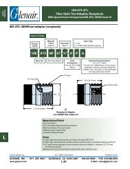
Loosely assembly the adapter to the<br />
connector and push back the backshell braid.<br />
Insert the wire bundle into the adapter and<br />
bottom it against the connector. Holding the<br />
cable, mark or tag the location where the shield<br />
support ring (<strong>Glenair</strong> Part Number 687-207) will<br />
be located. This distance may vary depending<br />
on your technique and the flexibility of the wire<br />
bundle immediately to the rear of the saddles<br />
(Figure 1).<br />
At the marked location, near the shield<br />
support ring, wrap tape around wire bundle for<br />
snug fit of shield support ring (Figure 1). Tape<br />
wrap is optional.<br />
You can then slide the overall braid from the<br />
wire bundle side over the shield support ring,<br />
trimming braid ends and tucking extra braid<br />
underneath itself for a clean appearance.<br />
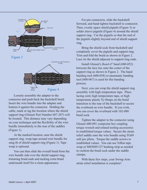
For pin connectors, slide the backshell<br />
forward, and hand tighten backshell to connector.<br />
Then, evenly space shield pigtails (Figure 3) or<br />
solder sleeve pigtails (Figure 4) around the shield<br />
support ring. Cut the pigtails so that the end of<br />
the pigtails slightly beyond end of shield support<br />
ring.<br />
Bring the shield sock from backshell and<br />
completely cover the pigtails and support ring.<br />
Trim and fold the braid as shown in Figure 2.<br />
Lace tie the shield adjacent to support ring ends.<br />
Install <strong>Glenair</strong>'s Band-it ® band (600-052)<br />
between the lace ties onto the center of the<br />
support ring as shown in Figure 2. The hand<br />
banding tool (600-058) or pneumatic banding<br />
tool (600-067) is used for this banding<br />
process.<br />
Next, you can wrap the shield support ring<br />
assembly with high temperature tape. Place<br />
lacing cord, high temperature tape, or high<br />
temperature plastic Ty-Straps on the braid<br />
transition to the rear of the backshell to secure<br />
the overbraid on wire bundle. If you wish,<br />
you can cover the overbraid with 102-080<br />
braid sock.<br />
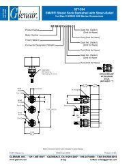
Tighten the adapter to the connector using<br />
<strong>Glenair</strong> 600-091 composite hex coupling<br />
torque wrench and related tooling accessories<br />
to established torque values. Secure the strain<br />
relief saddle onto the wire bundle using TG69<br />
soft jaw pliers. Torque the saddle screws to<br />
established values. You can use Teflon tape<br />
wrap or M85049/127 bushing strip as needed<br />
to cushion the braid sock under the saddle<br />
clamps.<br />
With these few steps, your Swing-Arm<br />
strain relief installation is complete!<br />
QwikConnect <br />
· <strong>April</strong> <strong>2007</strong> 7