Chapter 13 Gas Turbine Power Plants
Chapter 13 Gas Turbine Power Plants
Chapter 13 Gas Turbine Power Plants

Create successful ePaper yourself
Turn your PDF publications into a flip-book with our unique Google optimized e-Paper software.
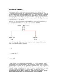
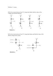
Air In<br />
Regenerator<br />
•* — ———<br />
05<br />
02'<br />
I ———<br />
Compressor<br />
03,<br />
——— ^ ——<br />
^<br />
<strong>Turbine</strong><br />
<strong>Turbine</strong><br />
Exhaust<br />
.. 04'<br />
Figure <strong>13</strong>.5 <strong>Gas</strong> turbine plant with regeneration<br />
called the brake specific fuel consumption (bsfc), as defined in<br />
(11.17).<br />
In applications of gas turbines for road vehicles, railroad locomotives<br />
and ship propulsion a power turbine may be used. This<br />
requires two turbines on separate shafts, each running at a different<br />
speed. Figure <strong>13</strong>.6 shows a typical arrangement: a highpressure<br />
(H.P.) turbine driving the compressor and a low-pressure<br />
(L.P.) turbine driving the load. As shown in the figure, the H.P.<br />
turbine and compressor are on the same shaft. This unit is called a<br />
gas generator, because it supplies gas to the power turbine but<br />
drives no load itself. Since the gas generator drives no load, the<br />
work of the H.P. turbine equals the work of the compressor.<br />
When a power turbine is used to drive a generator, no gear box is<br />
required, as with a single-shaft engine. Also for traction purposes<br />
the torque-speed characteristics of the power turbine are more favorable<br />
than those of the dual-purpose turbine.