CORRIGENDUM No. 2 - Yap State Government
CORRIGENDUM No. 2 - Yap State Government
CORRIGENDUM No. 2 - Yap State Government

You also want an ePaper? Increase the reach of your titles
YUMPU automatically turns print PDFs into web optimized ePapers that Google loves.
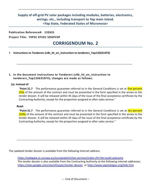
Supply of off-grid PV solar packages including modules, batteries, electronics,<br />
wirings, etc., including transport to <strong>Yap</strong> main island.<br />
<br />
Publication Reference#: 132631<br />
Project Title: YSPSC EFII01 SOGPVSP<br />
<strong>CORRIGENDUM</strong> <strong>No</strong>. 2<br />
1 Instructions to Tenderers (c4b_itt_en_instruction to tenderers_<strong>Yap</strong>132631EFII)<br />
1. In the document Instructions to Tenderers (c4b_itt_en_instruction to<br />
tenderers_<strong>Yap</strong>132631EFII), changes are made as follows:<br />
(a). Instead of:<br />
“Point 21.7 The performance guarantee referred to in the General Conditions is set at five percent<br />
(5%) of the amount of the contract and must be presented in the form specified in the annex to the<br />
tender dossier. It will be released within 45 days of the issue of the final acceptance certificate by the<br />
Contracting Authority, except for the proportion assigned to after-sales service.”<br />
Read:<br />
“Point 21.7 The performance guarantee referred to in the General Conditions is set at ten percent<br />
(10%) of the amount of the contract and must be presented in the form specified in the annex to the<br />
tender dossier. It will be released within 45 days of the issue of the final acceptance certificate by the<br />
Contracting Authority, except for the proportion assigned to after-sales service.”<br />
The updated tender dossier is available from the following Internet address:<br />
https://webgate.ec.europa.eu/europeaid/online-services/index.cfmdo=publi.welcome<br />
The tender dossier is also available from the Contracting Authority at the following internet addresses:<br />
https://sites.google.com/site/ef2yspsc/tender-dossier or http://www.yapstategov.org/bids.htm<br />
--- End of Document –
Supply of off-grid PV solar packages including modules, batteries, electronics,<br />
wirings, etc., including transport to <strong>Yap</strong> main island.<br />
<br />
Publication Reference#: 132631<br />
Project Title: YSPSC EFII01 SOGPVSP<br />
CLARIFICATIONS TO TENDERERS<br />
1 Tender Clarification Requests and Responses:<br />
I. Clarification Requests/Reponses<br />
II. (Attachment) PPA/SEAIPI Off Grid PV Power Systems Design Guidelines<br />
III. (Attachment) Letter of derogation # DEVCO/H3/BD/D (2011)<br />
1. Tender Clarification Requests and Responses:<br />
I. Clarification Requests/Reponses<br />
(a). Clarification Request #1:<br />
Annex III (Solar Batteries)<br />
As discussed with our production department on the Technical Sheet of 6V per battery requirement -<br />
"Each battery shall be a 6 volts DC (Vdc) in one robust container only, giving 6 V as nominal operating<br />
voltage; inter-cell connection shall not be exposed" - our battery is 2V per cells and provide inner-cell<br />
connector for battery bank but not produce as 6V in one robust container. Will such battery bank be<br />
acceptable<br />
Response:<br />
Yes, 6 volt or 2 volt cells will be accepted as long as the overall specifications are met.<br />
(b). Clarification Request #2:<br />
Annex III (Solar Batteries)<br />
We note that you required Flooded batteries, however will other types also be acceptable such as; GEL,<br />
ASTM, VRLA or other<br />
Response:<br />
<strong>No</strong>, only flooded batteries will be accepted.<br />
(c). Clarification Request #3:<br />
What is the exact delivery time– In the tender documents120 days as well as150 days are mentioned.<br />
Response:<br />
120 days, refer to Article 19 of the Special Conditions.<br />
(d). Clarification Request #4:<br />
Concerning the CD that shall accompany the offer – does it have to contain only the financial offer as a pdf<br />
or all documents of the offer
Response:<br />
The CD has to contain all submitted documents from the tenderer.<br />
(e). Clarification Request #5:<br />
It is nothing mentioned about the size of the containers to deliver the goods. Are there any requirements<br />
It is also not clear about the containers whether they are only used for delivering and going back to the<br />
tenderer or if you are going to keep them<br />
Response:<br />
Only 20’ containers can be accepted in <strong>Yap</strong> harbor. The containers can go back to the tenderer.<br />
(f). Clarification Request #6:<br />
PV Module Mounting Structure<br />
Can you please clarify if we also have to supply the post/poles for the array mounting structure<br />
Response:<br />
<strong>No</strong>, the modules will be ground-mounted on a concrete structure prepared by YSPSC. It is however<br />
important to include the technical drawings of the proposed mounting structure.<br />
(g). Clarification Request #7:<br />
Charge Controllers<br />
For a SCS the charge controller is specified to be 70A at 48V. Our question is can we offer a lesser amps<br />
controller than 70A if our array voltage will be configured at higher voltage to charge the 48V battery bank<br />
via MPPT technology.<br />
Response:<br />
You can offer an alternative design that we can look into however the official proposal needs to comply<br />
with the requested specs. <strong>No</strong>te that the specifications ask for a 48 V system and 3,360 Wp. It is however,<br />
possible to parallel 2 or 3 charge controllers, if this is recommended by the manufacturer. Please refer to<br />
point e.8 of Annex II.<br />
(h). Clarification Request #8:<br />
Wires, connectors and fuses<br />
Could please specify the cable run between the PV Module to Charge controller and the cable run<br />
between charge controller and battery for the SCS<br />
Response:<br />
The tender documents ask the tenderer under point g.2 to specify the wire sizes for the SCS with the note<br />
that “All wiring must be sized to keep line voltage losses to less than two percent (2%) in each sub-circuit<br />
and to allow the circuit to operate at a maximum of 60deg Celsius within the ampacity rating of the cable.”<br />
Voltage drop calculations need to be included in the proposal.<br />
(i). Clarification Request #9:<br />
Will 12V batteries be considered as well (e.g. 12V 190Ah for SHS)<br />
Response:<br />
<strong>No</strong>, the specs need to comply with the technical tender document. We have left a window open to send<br />
besides the offer that follows the set specification to propose and alternative design. For now only 6V and<br />
2V batteries will be accepted.<br />
(j). Clarification Request #10:<br />
Typically larger charge controllers (45A and above), function only as a charge controller or a load
controller, meaning that each unit does not have the capacity to control battery charge as well as load<br />
output. As the SCS system has an inverter, there is no need for the charge controller to also control the<br />
load. Thus requesting a charge controller “for a load of 70A (in 48V – 3360W)” isn’t really relevant.<br />
According to our design, a 60A charge controller is more than sufficient to manage the current from the<br />
PV array which is the primary concern when choosing such components. Please specify whether this will<br />
be acceptable.<br />
Response:<br />
<strong>No</strong>, the specs need to comply with the technical tender document. We have left a window open to send<br />
besides the offer that follows the set specification to propose and alternative design.<br />
(k). Clarification Request #11:<br />
Will 24V nominal panels with 72 cells be considered Typically panels that are larger than 130W are 24V<br />
with 72 cells, and the requirements have allowed panels up to 185W.<br />
Response:<br />
<strong>No</strong>, the specs need to comply with the technical tender document. We have left a window open to send<br />
besides the offer that follows the set specification to propose and alternative design.<br />
(l). Clarification Request #12:<br />
For the SHS will 12V designs be considered If there are 12V DC loads to be used with the system, such as<br />
lights, then a system voltage of 12V would be beneficial and eliminate the need of a DC to DC converter<br />
within the system. It also opens up the range of inverters, as 24V 300W inverters are more difficult to find<br />
that 12V 300W inverters.<br />
Response:<br />
<strong>No</strong>, the specs need to comply with the technical tender document. We have left a window open to send<br />
besides the offer that follows the set specification to propose and alternative design.<br />
It is however possible that YSPSC might go for the 12V option therefore the charge controllers need to be<br />
able to work with 12V and with 24V.<br />
(m). Clarification Request #13:<br />
Regarding the panel warranty and the following excerpt from Annex II;<br />
The PV modules shall be warranted for at least 20 years and must not experience more than 15% of rated<br />
capacity reduction in output over their lifetime. They also shall be warranted for physical defect for a<br />
period of 10 years.<br />
Typically modules are supplied with 5 year physical defect warranty and 20 or 25 year warranty for a<br />
reduction in power output no greater than 20%. Please specify whether this standard warranty will be<br />
accepted If not please recommend a supplier offering a warranty for rated capacity reduction in output<br />
of only 15%.<br />
Response:<br />
The specifications are the basis of warranty guidelines that are to be met. However alternative warrantees<br />
shall be noted and will be considered but perhaps lead to a lower rating in the evaluation process if higher<br />
warrantees are offered by other tenderers.<br />
As per contract guidelines recommendations of specific suppliers meeting this warranty are not allowed.<br />
(n). Clarification Request #14:<br />
For the SHS both 10mm2 and 6mm2 cables have been specified, please state whether these are required<br />
to be double or single core cables<br />
Response:<br />
The SHS 10mm2 and 6mm2 cables are to be provided as per the specifications of “Annex II g.) wires,<br />
connectors and fuses” and “Annex III 1.8 Wires, connectors and fuses – Ref to g.)” and shall be standard<br />
and flexible insulated single core copper cables.
(o). Clarification Request #15:<br />
REFERENCE IS MADE TO TECHNICAL SPECIFICATIONS ITEM 1.2 AND ITEM 2.2 (MOUNTING RAILS): Please<br />
clarify how the mounting rails should be done. Have they to be deemed for ground mounting or roof<br />
mounting In case of ground mounting please clarify if a steel or aluminium pole must be supplied.<br />
Response:<br />
The tender dossier states that the panels will be ground mounted – see Annex II-specifications b.2 and b.3.<br />
<strong>No</strong> poles need to be provided as the footing (poles) will be made of concrete and completed by YSPSC. The<br />
tenderer will have to send, however, their technical drawing of the mounting structure they propose. – see<br />
Annex II-specifications b.3.<br />
(p). Clarification Request #16:<br />
REFERENCE IS MADE TO TECHNICAL SPECIFICATIONS: Please clarify if the inverters and charge controller<br />
must be mounted on an electrical control board. If so should the supplier deliver them pre-mounted on<br />
the electrical board or the end users will take care of mounting Moreover, in case of electrical board are<br />
to be supplied which kind of electrical board do you need Which would be the IP protection number<br />
Response:<br />
The design of the PV system is up to the tenderer and the most appropriate design will be selected. Please<br />
note that we follow the technical guidelines for the pacific islands for the design, find attached a copy of<br />
these guidelines.<br />
(q). Clarification Request #17:<br />
REFERENCE IS MADE TO TECHNICAL SPECIFICATIONS<br />
Should the bidder supply earth grounding with earth rod<br />
Response:<br />
Yes, see technical guide and the NEC electrical code for off-grid PV installations.<br />
(r). Clarification Request #18:<br />
REFERENCE IS MADE TO THE TENDER SCOPE: Does the contract include installation or only delivery CIF In<br />
case the contract includes installation please send us the list of installation sites.<br />
Response:<br />
<strong>No</strong> installation is required under this tender.<br />
(s). Clarification Request #19:<br />
REFERENCE IS MADE TO INVERTERS QUANTITY: Please confirm that inverter quantities is 400 and -in any<br />
case - a 10% extra inverter must be included as spare parts<br />
Response:<br />
The requested quantity is 400 Sinewave inverters 24Vdc 120 Vac 60Hz 300W plus 10% spares and 20 Sine<br />
wave inverter 48Vdc 120Vac 60Hz 3000W plus 10% spares<br />
(t). Clarification Request #20:<br />
Rules of Origin: Clause 3 of Instructions to Tenderers.<br />
Please provide list of countries applicable for this project. Could you provide us with the copy of the<br />
Reference note of derogation # DEVCO/H3/BD/D (2011)<br />
Response:<br />
See the attached copy of the “Letter of Derogation”:
(u). Clarification Request #21:<br />
Photovoltaic Modules – a.4);<br />
PV modules must be framed with marine graded aluminum. I believe this refers to Anodized Aluminum<br />
frame<br />
Response:<br />
Anodized Aluminum will also be accepted<br />
(v). Clarification Request #22:<br />
Photovoltaic Modules – a.4);<br />
NEC requires PV Power Source to have Disconnect Switches, is this required for this project<br />
Response:<br />
Yes – All NEC guidelines must be followed<br />
(w). Clarification Request #23:<br />
Photovoltaic Modules – a.4);<br />
Confirm that PV Structure will be grounded using grounding bolts, lugs & screws<br />
Response:<br />
Correct<br />
(x). Clarification Request #24:<br />
Photovoltaic Modules – a.4);<br />
Please confirm if these structures will be mounted on a concrete pad embedded in ground<br />
Response:<br />
The systems will be installed on concrete poles. The poles will be prepared by YSPSC but the tenderer must<br />
provide the technical drawings of the mounting requirements for the system that they are proposing<br />
(y). Clarification Request #25:<br />
Solar Batteries;<br />
Will batteries with higher number of cycles be given preference over the price<br />
Response:<br />
Yes – All components must meet and/or exceed tender dossier specification<br />
(z). Clarification Request #26:<br />
Solar Batteries;<br />
Will batteries that have never been used in Pacific Island be considered if they meet the specifications are<br />
better priced over the battery that has proven track record in Pacific Island but may be higher in price<br />
Response:<br />
Yes – All components must meet and/or exceed tender dossier specification<br />
(aa). Clarification Request #27:<br />
Solar Batteries;<br />
Will batteries be given preference with 5 years Guarantee instead of warranty<br />
Response:<br />
Refer to the tender specifications for batteries that shall be follow and require a “warranty”
(bb). Clarification Request #28:<br />
Solar Batteries;<br />
NEC requires each equipment to have disconnect switch, is this required for this project<br />
Response:<br />
All NEC guidelines must be followed. All main components shall be able to be disconnected by a breaker<br />
and/or disconnect switch<br />
(cc). Clarification Request #29:<br />
Solar Batteries;<br />
Any preference on Battery Casing – transparent, clear etc<br />
Response:<br />
<strong>No</strong> preference is given to the color of the battery casing, but note that the acid level must be visible from<br />
outside.<br />
(dd). Clarification Request #30:<br />
Battery Enclosures;<br />
Will the Batteries be installed indoors or outdoors<br />
Response:<br />
Outdoors<br />
(ee). Clarification Request #31:<br />
Battery Enclosures;<br />
Any specific requirement for Battery Enclosure Material<br />
Response:<br />
The battery enclosure must have a long lifetime and must be suitable for outdoor marine environment<br />
usage.<br />
(ff). Clarification Request #32:<br />
Battery Enclosures;<br />
Do you intend to attach the Enclosure to the wall or floor or it will be just sitting on the ground etc<br />
Response:<br />
On the ground<br />
(gg). Clarification Request #33:<br />
Charge Controllers (SHS & SCS);<br />
Will MPPT Charge Controllers be considered for this project, MPPT Charge controllers are more efficient<br />
but there is cost difference as well<br />
Response:<br />
Yes<br />
(hh). Clarification Request #34:<br />
Charge Controllers (SHS & SCS);<br />
Is Battery Temperature Sensor required for temperature compensation charging, this will be of great help<br />
due to temperature variance<br />
Response:<br />
Refer to the requirements in the technical specifications for charge controllers. For the SCS a battery sensor<br />
would be required
(ii). Clarification Request #35:<br />
Since the panels will be installed outside and the controller inside, do we have to provide disconnect<br />
switches at the Array and also before the Charge Controller Entry. This means 2 disconnection points<br />
between the PV Array and Charge Controller. Please confirm.<br />
Response:<br />
Refer to the tender specifications for your systems designs for installation. These systems are to be<br />
packaged component stand-alone outside compact systems which are to be installed as complete units<br />
externally from the location being served by each system. All NEC guidelines must be followed as needed<br />
for design. Follow the instructions and you can include changes and/or additions in your design for<br />
evaluation.<br />
(jj). Clarification Request #36:<br />
As per the NEC guidelines, we can isolate one conductor and ground the other conductor or isolate both<br />
current carrying conductors by using appropriate circuit breakers. Please confirm if we can to supply these<br />
isolators / disconnection devices with this tender<br />
Response:<br />
All NEC and SEIAPI technical guidelines must be followed for design of stand-alone system. The guidelines<br />
are available online and have been attached with this email. The tenderer must design the system<br />
following these guidelines.<br />
(kk). Clarification Request #37:<br />
We have a question regarding the mounting structures for the modules.<br />
Will they be rammed into the ground or will there be a concrete foundation<br />
Response:<br />
The systems will be installed on concrete poles. The poles will be prepared by YSPSC but the tenderer<br />
proposal must provide the technical drawings for the poles along with the mounting requirements for the<br />
system/s that they are proposing.<br />
(ll). Clarification Request #38:<br />
Since SCS will be installed outside (compact installation)<br />
please confirm if both the controllers, inverters and all other accessories to be installed outside<br />
Response:<br />
SCS to be outside and please refer to the complete tender dossier and especially the documents of<br />
“Instruction for Tenderers” long with “Annex II” for definition of “PV solar packages” and “complete”<br />
system for both the SCS/SHS. All system components to be included with such.<br />
(mm). Clarification Request #39:<br />
Is SHS also a compact system with controllers and inverters mounted outdoors<br />
Response:<br />
Correct and again please refer to tender document Annex II item “h).” which provides guide to the region<br />
and conditions of the where these systems will be installed. Reference to “<strong>Yap</strong>, Federated <strong>State</strong>s of<br />
Micronesia” is made and which also encompasses the outer islands of the state of <strong>Yap</strong>, FSM. Research and<br />
becoming familiar with this region and the conditions that can be encountered is strongly encouraged.<br />
(nn). Clarification Request #40:<br />
Confirmation on Tender Guarantee<br />
If TG is submitted in another form, say Bank Guarantee or Bank Draft, will the company be disqualified<br />
from the tendering process
Response:<br />
The tender dossier requires that EU “Tender Guarantee Form” format must be used and submitted with the<br />
tender proposal<br />
(oo). Clarification Request #41:<br />
“Continuous Power at 25°C minimum 300W – maximum 400W”<br />
We can offer an Inverter with this value expressed in [VA] instead of [W]. Due to the missing data on<br />
number and type of devices that will be loaded by the grid-off plants, we cannot give the value for<br />
Continuous power expressed in [W]. Would you please be so kind to tell us if the range of Continuous<br />
power of 650-800 [VA] will be good as well.<br />
Exactly the same thing we would like to know regarding the technical specification for SCS plants as<br />
follows:<br />
“Continuous Power at 25°C minimum 3000W – max.3500W”<br />
Our proposal for the Continuous power is 5000 [VA] .Could it be suitable for SCS needs<br />
Response:<br />
It is acceptable to express the inverter values in “VA” as well as “W”. The ratings shall be within the<br />
guideline ranges as noted in the specifications of Annex II f.1) and f.2). Each tenderer must conclude to the<br />
best of their knowledge the best practiced design and component/materials provision meeting the<br />
specified guidelines. The overall design and technical specifications will be given preference and systems<br />
with established histories of performance shall be preferred.<br />
(pp). Clarification Request #42:<br />
Equipment delivery must be carried out in kits, in a grouped format, or it can be delivered each of their<br />
components separately: panels, regulators, inverters, batteries and accessories.”<br />
Response:<br />
Reference to “Equipment Delivery in kits” is not found & therefore refer to Annex II document (Annex II -<br />
Specificationsv2_final) related to this components delivery question as to be “supplies are to be made in<br />
one lot and to be delivered….”<br />
(qq). Clarification Request #43:<br />
At point a.3) of technical specifications standard IEEE 1262 is required<br />
IEEE 1262 served its purpose as the first consensus qualification test standard for thin film modules but, in<br />
this tender, are silicon types. Therefore, the standard IEEE 1262 is not applicable.<br />
Response:<br />
This is a United <strong>State</strong>s informational standard basis for PV panels that tenderers shall refer to for<br />
establishing their proposal submissions and is for reference purposes. Any subsequent standard/s for PV<br />
module qualification guidelines that have replaced and/or succeeded prior recommended practices shall be<br />
the responsibility of the tenderer and shall be followed.
II.<br />
(Attachment) PPA/SEAIPI Off Grid PV Power Systems Design Guidelines<br />
PPA/SEAIPI Off Grid PV<br />
Power Systems Design<br />
Guidelines
OFF GRID PV POWER SYSTEMS<br />
SYSTEM DESIGN GUIDELINES<br />
These guidelines have been developed by the Sustainable Energy Industry Association of the Pacific Islands in<br />
Collaboration with the Pacific Power Association<br />
They represent latest industry BEST PRACTICE for the design and installation of PV Grid Connect Systems.<br />
© Copyright 2012<br />
While all care has been taken to ensure this guideline is free from omission and error, no responsibility can be taken<br />
for the use of this information in the design of any PV grid connect system.<br />
Issue 1 September 2012
GENERAL<br />
The design of any off-grid system should consider, other than the electrical load, a number of criteria such as:<br />
o Budget<br />
o Acceptable genset runtime<br />
o Power quality<br />
o <strong>No</strong>ise levels<br />
o Environmental impact<br />
o Site accessibility<br />
o Aesthetics<br />
o Level of automation<br />
<strong>No</strong>te: This guidelines are based on d.c. bus systems and do not include the new a.c. bus hybrid systems currently available. Guidelines dedicated to<br />
hybrid Systems will be developed.<br />
ENERGY SOURCE MATCHING<br />
Heating and lighting should be supplied from the most appropriate source. For example -<br />
o cooking - gas or wood burning stove<br />
o water heating - solar water heating with gas or wood backup<br />
o Lighting - electrical lighting most often used but natural light ( daylighting ) should be considered.<br />
ENERGY EFFICIENCY<br />
All appliances should be chosen for the lowest possible energy consumption for each desired outcome, such<br />
as<br />
o High efficiency lighting<br />
o Energy efficient refrigeration<br />
STANDARDS for DESIGN<br />
System designs should follow any standards that are typically applied in the country or region where the solar<br />
installation will occur. The following lists the relevant standards in Australia, New Zealand and USA They are<br />
listed because some Pacific island countries and territories do follow those standards. These standards are<br />
often updated and amended so the latest version should always be applied.<br />
In Australia and New Zealand the main standards required include:<br />
o AS/NZS3000 Wiring Rules<br />
o AS/NZS4509 Stand-alone power systems<br />
o AS 4086.2 Secondary batteries for stand-alone power supplies<br />
o AS/NZS5033 PV Array<br />
o AS 3010.1 Electrical Installations - Supply Generating set<br />
o AS 1768 Lightning Protection<br />
o AS 3595 Energy management programs<br />
o AS 1359.51 <strong>No</strong>ise level limits<br />
In USA PV systems must be in accordance with the following codes and standards:<br />
o Electrical Codes-National Electrical Code Article 690:Solar Photovoltaic Systems and NFPA 70<br />
Uniform Solar Energy Code<br />
o Building Codes- ICC, ASCE 7<br />
o<br />
o<br />
UL Standard 1701: Flat Plat Photovoltaic Modules and Panels<br />
UL Standard 1741: Standard for Inverter, converters, Controllers and Interconnection System<br />
Equipment for use with Distributed Energy Resources<br />
Issue 1 September 2012 Page 1
INTRODUCTION<br />
Four major issues arise when designing a system:<br />
1. the load (power) required to be supplied by the system is not constant over the period of one day;<br />
2. the daily energy usage varies over the year;<br />
3. the energy available from the PV array may vary from time to time during the day;<br />
4. the energy available from the PV array will vary from day to day during the year.<br />
Since the system is based on photovoltaic modules, then a comparison should be undertaken between the<br />
available energy from the sun and the actual energy demands The worst month is when the ratio between<br />
solar energy available and energy demand is smallest.<br />
The design of an off-grid power requires a number of steps. A basic design method follows:<br />
1. Determination of the energy usage that the system must supply.<br />
2. Determination of the battery storage required.<br />
3. Determination of the energy input required from the PV array or other sources (eg battery<br />
charger/generator)<br />
4. Selection of the remainder of system components.<br />
LOAD (ENERGY) ASSESSMENT<br />
Electrical power is supplied from the batteries (DC) or via an inverter to produce either 230 volts AC (South<br />
Pacific) or 110 / 120 volts AC (<strong>No</strong>rth Pacific). Electrical energy usage is normally expressed in watt hours (Wh)<br />
or kilowatt hours ( kWh ).<br />
To determine the daily energy usage for an appliance, multiply the power of the appliance by the number of<br />
hours per day it will operate. The result is the energy (Wh) consumed by that appliance per day.<br />
Appliances can either be DC or AC. An energy assessment should be undertaken for each type, examples of<br />
these are shown in tables 1 and 2.<br />
You need to calculate the electrical energy usage with the customer. Many systems have failed over the years<br />
not because the equipment has failed or the system was installed incorrectly, BUT BECAUSE THE<br />
CUSTOMER BELIEVED THEY COULD GET MORE ENERGY FROM THEIR SYSTEM THAN THE SYSTEM<br />
COULD DELIVER. It failed because the customer was unaware of the power/energy limitations of the<br />
system.<br />
The problem is that the customer may not want to spend the time determining their realistic power and energy<br />
needs which is required to successfully complete a load assessment form. They just want to know: How much<br />
for a system to power my lights and TV<br />
A system designer can only design a system to meet the power and energy needs of the customer. The<br />
system designer must therefore use this process to understand the needs of the customer and at the same<br />
time educate the customer. Completing a load assessment form correctly (Refer to table 1 and 2 below) does<br />
take time; you may need to spend 1 to 2 hours or more with the potential customer completing the tables. It is<br />
during this process that you will discuss all the potential sources of energy that can meet their energy needs<br />
and you can educate the customer on energy efficiency.<br />
Issue 1 September 2012 Page 2
Worked Example<br />
Table 1 DC Load (energy) Assessment<br />
(1) (2) (3) (4a) (5a) (4b) (5b) (6) Comments<br />
dry season wet season Contribution<br />
Power<br />
to maximum<br />
Appliance Number<br />
Usage Energy Usage Energy demand<br />
Time<br />
Time<br />
W h Wh h Wh W<br />
Light 4 7 4 112 4 112 28<br />
Daily Load energy-d.c loads (Wh) ( DC 7a) 112 (DC 7b) 112<br />
Maximum d.c. demand (W) (DC 8) 28<br />
Table 2 AC Load (energy) Assessment<br />
(1) (2) (3) (4a) (5a) (4b) (5b) (6) (7) (8) (9a) (9b)<br />
dry season wet season<br />
Contribution<br />
Contribution to<br />
Power<br />
to max<br />
surge demand<br />
Appliance <strong>No</strong>.<br />
Power demand Surge Potential Design<br />
Usage<br />
Time<br />
Energy Usage<br />
Time<br />
Energy Factor<br />
Factor<br />
Comments<br />
W h Wh h Wh VA VA VA<br />
TV 100 3 300 3 300 0.8 125 4 500 125<br />
Refrigerator 100 12 1200 12 1200 0.8 125 4 500 500 Duty cycle of<br />
0.5 included<br />
Daily Load Energy A.C<br />
1500<br />
1500<br />
Loads (Wh) (AC10a)<br />
(AC10b)<br />
maximum demand (VA) (AC11) 250 1000<br />
Surge demand (VA) (AC12) 625<br />
Issue 1 September 2012 Page 3
In the worked example on the previous page, the TV and refrigerator are using AC electricity so we have to<br />
take into account the efficiency of the inverter. Typically the peak efficiency of the inverter may be over 90%<br />
but in many systems the inverter will sometimes be running when there is very little load on the inverter, so the<br />
average efficiency is about 85% to 90%. Then we must divide the total AC energy used by this figure to obtain<br />
the energy required to be supplied to the inverter from the battery bank.<br />
For the worked example assume the efficiency of the chosen inverter is 90%.<br />
Daily battery load (energy) from AC loads = 1500Wh ÷ 0.9 = 1667 Wh<br />
Daily battery load (energy) from DC loads = 112 Wh<br />
To get the total load(energy) as seen by the battery, you add the two figures together:<br />
1667 + 112= 1779Wh<br />
If there are no AC loads, then you only have to work out the load from the DC appliances, and not include the<br />
inverter (or the inverter efficiency).<br />
BATTERY SELECTION<br />
DETERMINATION OF SYSTEM VOLTAGE<br />
System voltages are generally 12, 24 or 48 Volts. The actual voltage is determined by the requirements of the<br />
system. For example, if the batteries and the inverter are a long way from the energy source then a higher<br />
voltage may be required to minimise power loss in the cables. In larger systems 120V or 240V DC could be<br />
used, but these are not typical household systems.<br />
As a general rule, the recommended system voltage increases as the total load increases. For small daily<br />
loads, a 12V system voltage can be used. For intermediate daily loads, 24V is used and for larger loads 48V is<br />
used.<br />
1 kWh 3-4 kWh<br />
Use 12 Volt<br />
system voltage<br />
Use 24 Volt<br />
system voltage<br />
Use 48 Volt<br />
system voltage<br />
The changes over points are roughly at daily loads of 1 kWh and 3-4 kWh but this will also be dependent on<br />
the actual power profile.<br />
One of the general limitations is that maximum continuous current being drawn from the battery should not be<br />
greater than 150A.<br />
BATTERY SIZING<br />
To convert Watt-hours (Wh) to Amp-hours (Ah) you need to divide by the battery system voltage.<br />
For the worked example the daily energy usage was 1779Wh , so we select a battery system voltage of 24<br />
Volts.<br />
This means that the daily Ah demand on the batteries will be:<br />
Issue 1 September 2012 Page 4
Ah = Wh ÷ system voltage 1779Wh ÷ 24 = 74 Ah<br />
So at the moment the minimum size battery to meet the daily energy requirements in the example is: 74Ah<br />
Battery capacity is determined by whichever is the greater of the following two requirements:<br />
1. The ability of the battery to meet the energy demand of the system, often for a few days, sometimes<br />
specified as ‘days of autonomy’ of the system;<br />
OR<br />
2. The ability of the battery to supply peak power demand.<br />
The critical design parameters include:<br />
Parameters relating to the energy requirements of the battery:<br />
a) Daily energy demand<br />
b) Daily and maximum depth of discharge<br />
c) Number of days of autonomy<br />
Parameters relating to the discharge power (current) of the battery:<br />
a) Maximum power demand<br />
b) Surge demand<br />
Parameters relating to the charging of the battery:<br />
a) Maximum Charging Current<br />
Based on the these parameters there are a number of factors that will increase the battery capacity in order to<br />
provide satisfactory performance. These correction factors must be considered.<br />
1. Days of Autonomy<br />
Extra capacity is necessary where the loads require power during periods of reduced input. The battery<br />
bank is often sized to provide for a number of days autonomy. A common period selected is 5 days.<br />
Where a generator is operating on a regular basis the autonomous period can be reduced.<br />
In other cases, where there is no auxiliary charging source, the period of autonomy is often increased to 7<br />
days or more.<br />
For the worked example assume 5 days autonomy .<br />
ADJUSTED<br />
Battery Capacity = 74 x 5 = 370 Ah<br />
2. Maximum Depth of Discharge<br />
Battery manufacturers recommend a maximum depth of discharge (DOD). If this is regularly exceeded the<br />
life of the battery is severely reduced. This could be 50% or for some solar batteries as high as 80%.<br />
For the worked example Assume a maximum DOD of 70%.<br />
ADJUSTED<br />
Battery Capacity = 370 ÷ 0.7 = 529 Ah<br />
3. Battery Discharge Rate<br />
The actual discharge rate selected is highly dependent on the power usage rates of connected loads. Many<br />
appliances operate for short periods only, drawing power for minutes rather than hours. This affects the battery<br />
Issue 1 September 2012 Page 5
selected, as battery capacity varies with discharge rate. Information such as a power usage profile over the<br />
course of an average day is required for an estimate of the appropriate discharge rate.<br />
For small systems this is often impractical.<br />
Where the average rates of power usage are low, the battery capacity for 5 days autonomy is often selected at<br />
the 100hr rate of discharge for the battery.<br />
For the worked example<br />
ADJUSTED<br />
Battery Capacity = 529 Ah (@ C 100 )<br />
Where average power usage rates are high, it may be necessary to select the battery capacity for 5 days<br />
autonomy at a higher discharge rate. eg. the 10 (C 10 ) or 20hr (C 20 ) rate<br />
4. Battery Temperature derating<br />
Battery capacity is affected by temperature. As the temperature goes down, the battery capacity reduces. The<br />
following graph gives a battery correction factor for low temperature operation. <strong>No</strong>te that the temperature<br />
correction factor is 1 at 25°C as this is the tempe rature at which battery capacity is specified.<br />
In the tropics it is often still 20°C+ in the even ings so unless the system is located in a mountainous region<br />
that does get cold then ignore the temperature derating. If you want to be conservative add 5% to the capacity<br />
to allow for this factor.<br />
BATTERY SELECTION<br />
Deep discharge type batteries / cells should be selected for the required system voltage and capacity in a<br />
single series string of battery cells.<br />
Parallel strings of batteries are not recommended.<br />
Where this is necessary each string must be separately fused.<br />
For the worked example a battery of at least 529 Ah (@C 100 ) should be used.<br />
PV ARRAY SIZING- Standard Switched Controllers<br />
The calculation for determining the size of the PV array is dependent on the type of controller used. Historically<br />
standard switched controllers were the most common controllers used. In recent years a number of maximum<br />
Issue 1 September 2012 Page 6
power point trackers (MPPT) have become available. This section determines how to size the PV array based<br />
on switched controllers based on the PV array meeting the daily load requirements all year. Later in the guide<br />
is a section on how to size a PV array using a MPPT.<br />
The size of the PV array should be selected to take account of:<br />
seasonal variation of solar irradiation<br />
seasonal variation of the daily energy usage<br />
battery efficiency<br />
manufacturing tolerance of modules<br />
dirt<br />
temperature of array (the effective cell temperature)<br />
Solar irradiation data is available from various sources. Some countries have data available from their<br />
respective meteorological department. One source for solar irradiation data is the NASA website:<br />
http:/eosweb.larc.nasa.gov/sse/. RETSCREEN, a program available from Canada, incorporates the NASA<br />
data and it is easier to use. Please note that the NASA data has, in some instances, had higher irradiation<br />
figures than that recorded by ground collection data in some countries. but if there is no other data available it<br />
is data that can be used.<br />
Solar irradiation is typically provided as kWh/m 2 however it can be stated as daily peak Sun Hours (PSH). This<br />
is the equivalent number of hours of solar irradiance of 1kW/m 2 .<br />
Attachment 1 provides data on the following sites:<br />
• Suva, Fiji (Latitude 18°08 ′S Longitude 178°25 ′E)<br />
• Apia, Samoa (Latitude 13 o 50' S' Longitude 171 o 44' W)<br />
• Port Vila, Vanuatu (Latitude 17° 44' S Longitude 168° 19' E)<br />
• Tarawa, Kiribati (Latitude 1°28'N, Longitude 173°2 'E)<br />
• Raratonga, Cook islands( Latitude 21°30'S, Longitude 160°0'W)<br />
• Nuku’alofa, Tonga (Latitude 21º14'S Longitude 175º22'W)<br />
• Honiara, Solomon Islands (Latitude 09°27'S, Lon gitude 159°57'E)<br />
• Koror ,Palau ( Latitude 7°20’N Longitude 134°28'E)<br />
• Ponapei, Pohnpei FSM (Latitude: 6°54'N, Longitude : 158°13'E)<br />
• Majuro, Marshall Islands (Latitude: 7º 12N, Longitude 171º 06E)<br />
• Alofi, Niue (Latitude 19°04' S. Longitude 169° 55' W)<br />
• Nauru (Latitude 0º55’S, Longitude 166º 91’E)<br />
• Tuvalu (Latitude 8°31 ′S, Longitude 179°13 ′E)<br />
• Hagåtña, Guam (Latitude 13°28 ′N Longitude: 144°45 ′E)<br />
• <strong>No</strong>umea, New Caledonia (Latitude 22°16 ′S Longitude: 166°27 ′E)<br />
• Pago Pago, American Samoa (Latitude 14°16 ′ S Longitude: 170°42 ′W)<br />
The variation of both the solar irradiation and the load energy requirement should be considered. If there is no<br />
variation in daily load between the various times of the year then the system should be designed on the month<br />
with the lowest irradiation that is peak sun hours (PSH).<br />
DAILY ENERGY REQUIREMENT FROM THE PV ARRAY<br />
In order to determine the energy required from the PV array, it is necessary to increase the energy from the<br />
battery bank to account for battery efficiency.<br />
.<br />
The average columbic efficiency (in terms of Ah) of a new battery is 90% (variations in battery voltage are not<br />
considered).<br />
For the worked example the daily energy requirement expressed in Ah from the battery is 74 Ah. Allowing for<br />
the battery efficiency, the solar array then needs to produce…<br />
74 Ah ÷ 0.9 = 82.2 Ah<br />
Assume the worst months PSH is 5.<br />
Issue 1 September 2012 Page 7
Therefore the required PV array output current is:<br />
82.2 Ah ÷ 5 PSH = 16.5 A<br />
OVERSIZE FACTOR<br />
If the system does not include a fuel generator which can provide extra charging to the battery bank then the<br />
solar array should be oversized to provide the equalisation charging of the battery bank. In Australia and New<br />
Zealand this is between 30% and 100%. It is recommended in the Pacific that this is 10%.<br />
For the worked example the adjusted array output current is:<br />
16.5A x 1.1 = 18.1 A<br />
DERATING MODULE PERFORMANCE<br />
The PV array will be de-rated due to:<br />
• Manufacturer’s Tolerance: Most manufacturers rate their modules ± a percentage (eg ±3%) or wattage<br />
(eg ±2W). Unless every module is tested and its actual rating is known then the modules should be derated<br />
by the manufacturer’s tolerance.<br />
• Dirt: Over a period of time dirt or salt (if located near the coast) can build up on the array and reduce<br />
the output. The output of the module should therefore be derated to reflect this soiling. The actual value<br />
will be dependent on the site but this can vary from 0.9 to 1 (i.e. up to 10% loss due to dirt).<br />
• Temperature: Modules’ output power decreases with temperature above 25°C and increases with<br />
temperatures below 25°C. The average cell temperatu re will be higher than the ambient because of the<br />
glass on the front of the module and the fact that the module absorbs some heat from the sun. The<br />
output power and/or current of the module must be based on the effective temperature of the cell. This<br />
is determined by the following formula:<br />
T cell-eff = T a.day + 25°C<br />
Where<br />
T cell-eff = the average daily effective cell temperature in degrees Celsius (°C)<br />
T a.day = the daytime average ambient temperature for the month that the sizing is being undertaken.<br />
Since the modules are used for battery charging, the current at 14 Volts (a good battery charging voltage) at<br />
the effective cell temperature should be used in calculations. If curves are unavailable to determine the current<br />
at effective cell temperature then use the <strong>No</strong>rmal Operating Cell temperature (NOCT) provided by the<br />
manufacturers.<br />
Therefore the derated module output current is calculated as follows:<br />
The Current of the module at 14V and effective cell temperature (or NOCT current)<br />
multiplied by derating due to manufacturers tolerance<br />
multiplied by derating due to dirt<br />
I (NOCT) x f man x f dirt<br />
If a module has a 3% (0.03) manufacturers tolerance, then the module current is derated by multiplying by<br />
0.97 (1-0.03).<br />
If a module has a 5% (0.05) loss due to dirt then the module current is derated by multiplying by 0.95 (1-0.05).<br />
For the worked example the selected module has a peak rating of 80W P .<br />
An 80 watt solar module (still used in many small off-grid systems) typically has the following data:<br />
Issue 1 September 2012 Page 8
Table 3: 80 W module data<br />
Rated Power<br />
80W<br />
Power Tolerance ± 5%<br />
<strong>No</strong>minal Voltage<br />
12V<br />
Maximum Power Voltage, V mp 17.6V<br />
Maximum Power Current, I mp 4.55A<br />
Open Circuit Voltage, V oc 22.1V<br />
Short Circuit Current, I sc 4.8A<br />
NOCT<br />
47±2°C<br />
Current at 14V and NOCT 4.75A<br />
Assuming a 5% dirt derating then the adjusted output current of the above module is:<br />
ADJUSTED<br />
Module current = I (NOCT) x 0.95 ( ← minus 5% for manufactures tol) x 0.95 ( ← minus 5% for dirt)<br />
= 4.75A x 0.95 x 0.95 = 4.29A<br />
NUMBER OF MODULES REQUIRED IN ARRAY<br />
First determine number of modules in series, To do this divide the system voltage by the nominal operating<br />
voltage of each module. In our example:<br />
For the worked example Number of modules in series = 24V ÷ 12V = 2<br />
Therefore the array must comprise of series connected strings of 2 modules.<br />
To determine the number of strings in parallel, the PV array output current required (in A) is divided by the<br />
output of each module (in A).<br />
For the worked example Number of strings in parallel =18.1A ÷ 4.29A = 4.22<br />
Do we round up or down If you want to be conservative you would round up. However in this example we<br />
suggest you round down since this calculation was based on the worst month and we allowed an oversize of<br />
10%.This does need to be determined for each system.<br />
For the worked example The number of modules in the array = 4 x 2 = 8<br />
The peak rating of the array is : 8 x 80W P = 640W P<br />
INVERTER SELECTION<br />
The type of inverter selected for the installation depends on factors such as cost, surge requirements, power<br />
quality and for inverter/chargers, a reduction of the number of system components necessary. Inverters are<br />
available in 3 basic output types - Square wave, modified square wave and sine wave.<br />
There are few square wave inverters used today.<br />
Modified square wave inverters generally have good surge and continuous capability and are usually cheaper<br />
than sine wave types. However, some appliances, such as audio equipment, television and fans can suffer<br />
because of the output wave shape.<br />
Sine wave inverters often provide a better quality power than the 230V (or 110V or 120V) grid supply.<br />
Issue 1 September 2012 Page 9
INVERTER SIZING<br />
The selected inverter should be capable of supplying continuous power to all AC loads<br />
AND<br />
providing sufficient surge capability to start any loads that may surge when turned on and particularly if they<br />
turn on at the same time.<br />
Where an inverter cannot meet the above requirements attention needs to be given to load control and<br />
prioritisation strategies.<br />
For the worked example<br />
From the load (energy) assessment on page 3, a selected inverter must be capable of supplying 250VA<br />
continuous with a surge capability of 625VA.<br />
CONTROLLERS- Standard Switched Controller<br />
PV controllers on the market range from simple switched units that only prevent the overcharge (and<br />
discharge) of connected batteries to microprocessor based units that incorporate many additional features<br />
such as …<br />
o<br />
o<br />
o<br />
o<br />
o<br />
PWM and equalisation charge modes<br />
DC Load control<br />
Voltage and current metering<br />
Amp-hour logging<br />
Generator start/stop control<br />
Unless the controller is a model that is currently limited these should be sized so that they are capable of<br />
carrying 125% of the array short circuit current and withstanding the open circuit voltage of the array. If there is<br />
a possibility that the array could be increased in the future then the controller should be oversized to cater for<br />
the future growth.<br />
(<strong>No</strong>te: sometimes the controller is called a regulator)<br />
For the worked example<br />
The controller chosen must have a current rating<br />
> 1.25 x 4 x 4.8 A = 24A at a system voltage of 24V.<br />
GENERATORS & BATTERY CHARGING<br />
To reduce system costs, it is common for some form of auxiliary charging to be used to provide energy when<br />
daily energy requirements are greater than the daily PV input into the system. This is usually a<br />
diesel/petrol/gas powered generator. Where the electrical output is 230V AC (or 110V or 120V) a battery<br />
charger is required.<br />
An inverter/charger can be used; otherwise a separate charger unit is needed.<br />
Factors that must be considered when using internal combustion generators are<br />
o Fuel storage and spillage precautions<br />
o <strong>No</strong>ise emission control<br />
o Ventilation<br />
o Generator loading<br />
With regards to generator loading, a generator should supply greater than 50% of its maximum rating while<br />
running. Loading of less than 50% increases running and maintenance costs and reduces generator life.<br />
Issue 1 September 2012 Page 10
( refer to genset manufacturers' information )<br />
BATTERY CHARGER SIZING<br />
A charger must be capable of supplying voltage greater than the nominal system voltage.<br />
The maximum charging current must not be greater than that recommended by the battery manufacturer but a<br />
usable estimate is a maximum charge current of around 10% of the C 10 rate.<br />
PV ARRAY SIZING- MPPT<br />
DAILY ENERGY REQUIREMENT FROM THE PV ARRAY<br />
The size of the PV array should be selected to take account of:<br />
seasonal variation of solar irradiation<br />
seasonal variation of the daily energy usage<br />
battery efficiency (wh)<br />
Cable losses<br />
MPPT efficiency<br />
manufacturing tolerance of modules<br />
dirt<br />
temperature of array (the effective cell temperature)<br />
With the standard controller the only sub-system losses was the battery efficiency and the calculations are<br />
undertaken using Ah. When using a MPPT the calculations are in Wh and the sub-system losses in the system<br />
include:<br />
• Battery efficiency (watthr)<br />
• Cable losses<br />
• MPPT efficiency<br />
In order to determine the energy required from the PV array, it is necessary to increase the energy from the<br />
battery bank to account for all the sub-system losses.<br />
For the worked example assume cable losses is 3% (transmission efficiency of 97%), MPPT efficiency of 95%<br />
and battery efficiency of 80%<br />
Subsystem efficiency = 0.97 x 0.95 x 0.8 = 0.737<br />
Energy required from the PV array = 1779Wh ÷ 0.737 = 2413Wh<br />
Assume the worst months PSH is 5.<br />
Therefore the required peak PV array output power is:<br />
2413Wh ÷ 5 PSH = 482W P<br />
OVERSIZE FACTOR<br />
If the system does not include a fuel generator which can provide extra charging to the battery bank then the<br />
solar array should be oversized to provide the equalisation charging of the battery bank. In Australia and New<br />
Zealand this is between 30% and 100%. It is recommended in the Pacific that this is 10%.<br />
For the worked example Therefore the adjusted array output current is:<br />
482W P x 1.1 = 530W P<br />
DERATING MODULE PERFORMANCE<br />
The PV array will be de-rated due to:<br />
Issue 1 September 2012 Page 11
• Manufacturer’s Tolerance: Most manufacturers rate their modules ± a percentage (eg ±5%) or wattage<br />
(eg ±2W). Unless every module is tested and its actual rating is known then the modules should be derated<br />
by the manufacturer’s tolerance.<br />
• Dirt: Over a period of time dirt or salt (if located near the coast) can build up on the array and reduce<br />
the output. The output of the module should therefore be derated to reflect this soiling. The actual value<br />
will be dependent on the site but this can vary from 0.9 to 1 (i.e. up to 10% loss due to dirt).<br />
• Temperature: Modules’ output power decreases with temperature above 25°C and increases with<br />
temperatures below 25°C. The average cell temperatu re will be higher than the ambient temperature<br />
because of the glass on the front of the module and the fact that the module absorbs some heat from<br />
the sun. The output power and/or current of the module must be based on the effective temperature of<br />
the cell. This is determined by the following formula:<br />
T cell-eff = T a.day + 25°C<br />
Where<br />
T cell-eff = the average daily effective cell temperature in degrees Celsius (°C)<br />
T a.day = the daytime average ambient temperature for the month that the sizing is being undertaken.<br />
With switched controllers the temperature effect was used to determine the operating current of the<br />
module/array. With MPPT’s the derating power factor must be calculated.<br />
The three main types solar modules available on the market each have different temperature coefficients.<br />
These are:<br />
• Monocrystalline: Modules typically have a temperature coefficient of –0.45%/ o C. That is for every<br />
degree above 25 o C the output power is derated by 0.45%.<br />
• Polycrystalline: Modules typically have a temperature coefficient of –0.5%/ o C.<br />
• Thin Film: Modules have a different temperature characteristic resulting in a lower co-efficient typically<br />
around 0%/°C to -0.25%/°C, but remember to check with the manufacturer<br />
The typical ambient daytime temperature in many parts of the Pacific is between 30 and 35 o C during some<br />
times of the year. So it would not be uncommon to have module cell temperatures of 55 o C or higher.<br />
For the worked example Assume the ambient temperature is 30 o C..<br />
Therefore the effective cell temperature is<br />
30 o C +25 o C = 55 o C<br />
Therefore this is 30 o C above the STC temperature of 25 o C.<br />
The 80 W P module used in this example is a polycrystalline module with a derating of -0.5%/ o C<br />
Therefore the losses due to temperature would be:<br />
Temperature loss = 30 o C x 0.5%/ o C = 15% loss<br />
This is a temperature derating factor of 0.85<br />
Assuming a 5% dirt derating then the adjusted output power of the 80W module is:<br />
Adjusted module power = 80 x 0.95 x 0.95 x 0.85 = 61.4W<br />
NUMBER OF MODULES REQUIRED IN ARRAY<br />
To calculate the required number of modules in the array, divide the required array power by the adjusted<br />
module power.<br />
Issue 1 September 2012 Page 12
For the worked example<br />
Number of modules in array =530 ÷ 61.4 = 8.63<br />
(<strong>No</strong>te for the switch regulator we had 4.29 parallel strings of 2 modules in series)<br />
The actual number of modules will be dependent on the MPPT selected. If it was 9 then the rating of the array<br />
is : 9 x 80W P = 720W P<br />
SELECTING MPPT<br />
The following table gives some examples of MPPT’s currently available on the market:<br />
Model d.c. battery<br />
Voltage (V)<br />
STECA<br />
Solarix<br />
MMP2010<br />
Phocos<br />
MMPT<br />
100/20-1<br />
Morningstar<br />
SS-MPPT-15L<br />
Outback Flex<br />
Max 80<br />
Outback Flex<br />
Max60<br />
Table 4: MPPT Data<br />
Input voltage Max d.c. Max(W) Solar<br />
range (V) Battery Array<br />
Current (A)<br />
12/24 17 to 100 20 250/500 10<br />
Max Load<br />
Current (A)<br />
12/24 Max 95 20 300/600 10<br />
12/24 Max 75 15 200/400 15<br />
12/24/36/48/60 Max 150 80 1250(12)<br />
2550(24)<br />
5000(48)<br />
7500 (60)<br />
12/24/36/48/60 Max 150 60 900(12)<br />
1800(24)<br />
3600(48)<br />
4500 (60)<br />
For the worked example<br />
Allowing for 125% oversizing then the required rating of the MPPT is:<br />
1.25 x 720Wp = 900 W<br />
From the table we would select the Outback Flexmax60 which has an array rating of 1800W @ 24V<br />
We could possibly use two of the others e.g. Phocos or Steca.<br />
MATCHING THE PV ARRAY TO THE MAXIMUM VOLTAGE SPECIFICATIONS OF THE MPPT<br />
The MPPT typically have a recommended minimum nominal array voltage and a maximum voltage. In the<br />
case where a maximum input voltage is specified and the array voltage is above the maximum specified, the<br />
MPPT could be damaged.<br />
Some MPPT controllers might allow that the minimum array nominal voltage is that of the battery bank.<br />
However the MPPT will work better when the minimum nominal array voltage is higher than the nominal<br />
voltage of the battery. The Outback range of MPPT’s requires that the minimum nominal array voltage is<br />
greater as shown in Table 5. Please check with the MPPT manufacturer because these could vary.<br />
Issue 1 September 2012 Page 13
Table 5 Minimum <strong>No</strong>minal Array Voltages (Outback MPPT’s)<br />
<strong>No</strong>minal Battery Voltage Recommended Minimum <strong>No</strong>minal Array<br />
voltage<br />
12V<br />
24V<br />
24V<br />
36V<br />
48V<br />
60V<br />
It is important that the output voltage of the string is matched to the operating voltages of the MPPT and that<br />
the maximum voltage of the MPPT is never reached.<br />
The output voltage of a module is affected by cell temperature changes in a similar way to the output power.<br />
The manufacturers will provide a voltage temperature coefficient. It is generally specified in V/°C (or mV/°C)<br />
but it can also be expressed as a % .<br />
To ensure that the V oc of the array does not reach the maximum allowable voltage of the MPPT the minimum<br />
day time temperatures for that specific site are required.<br />
In early morning at first light the cell temperature will be very similar to the ambient temperature because the<br />
sun has not had time to heat up the module. In the Pacific Islands the average minimum temperature is 20 0 C<br />
(this could be lower in some mountain areas) and it is recommended that this temperature is used to<br />
determine the maximum V oc. (<strong>No</strong>te: If installing in the mountains then use the appropriate minimum<br />
temperature. Many people also use 0°C, if appropriate for the ar ea). The maximum open circuit voltage is<br />
determined similar to the temperature derating factor for the power.<br />
For the worked example Assume the voltage co-efficient is 0.07V/ o C.<br />
If the minimum temperature is 20 o C this is 5 o C below the STC temperature of 25 o C. Therefore the effective<br />
variation in voltage is:<br />
5 x 0.07 = 0.35V<br />
So the maximum open circuit voltage of the module = 22.1V + 0.35V =22.45V<br />
Maximum number of modules that you can have in series = 150V ÷ 22.45V = 6.68 this is rounded down to 6.<br />
So the MPPT will allow between 3 and 6 modules in a string.<br />
The actual number of modules required was 8.68. If we round down to 8 (since an oversize factor of 10% and<br />
also worst month for PSH was used) then the array would be 2 parallel strings of 4 modules in series. If we<br />
round up to 9 then the solution could be 3 parallel strings with 3 modules in series.<br />
Issue 1 September 2012 Page 14
ATTACHMENT 1: : Table showing Peak Sunhrs for various sites and tilt angles.<br />
Location Peak Sunlight Hours (kWh/m²/day)<br />
Suva, Fiji Jan Feb Mar Apr May Jun Jul Aug Sep Oct <strong>No</strong>v Dec<br />
Annual<br />
Average<br />
Latitude: 18°08 ′ South 0° Tilt ¹ 6.29 6.2 5.54 4.67 4.05 3.72 3.89 4.44 5.08 6.04 6.32 6.38 5.21<br />
Longitude: 178°25 ′ East 18° Tilt ² 6.27 5.88 5.55 4.99 4.61 4.38 4.51 4.88 5.22 5.83 6.1 6.41 5.38<br />
33° Tilt ² 5.95 5.4 5.33 5.03 4.85 4.7 4.8 5 5.1 5.43 5.71 6.12 5.29<br />
Apia, Samoa Jan Feb Mar Apr May Jun Jul Aug Sep Oct <strong>No</strong>v Dec<br />
Annual<br />
Average<br />
Latitude: 13°50 ′ South 0° Tilt ¹ 5.39 5.47 5.16 5.09 4.63 4.46 4.71 5.25 5.77 5.91 5.76 5.51 5.25<br />
Longitude: 171°46 ′ West 13° Tilt ² 5.31 5.24 5.12 5.32 5.07 5 5.24 5.61 5.85 5.72 5.67 5.45 5.38<br />
28° Tilt ² 5.13 4.86 4.93 5.38 5.36 5.42 5.64 5.81 5.75 5.36 5.45 5.3 5.37<br />
Port Vila, Vanuatu Jan Feb Mar Apr May Jun Jul Aug Sep Oct <strong>No</strong>v Dec<br />
Annual<br />
Average<br />
Latitude: 17°44 ′ South 0° Tilt ¹ 6.68 6.2 5.76 4.98 4.2 3.79 4.04 4.75 5.65 6.47 6.67 6.93 5.5<br />
Longitude: 168°19 ′ East 17° Tilt ² 6.69 5.9 5.78 5.33 4.76 4.42 4.66 5.22 5.82 6.26 6.46 7.01 5.69<br />
32° Tilt ² 6.38 5.43 5.56 5.39 5.02 4.75 4.98 5.39 5.72 5.83 6.07 6.73 5.61<br />
Tarawa, Kiribati Jan Feb Mar Apr May Jun Jul Aug Sep Oct <strong>No</strong>v Dec<br />
Annual<br />
Average<br />
Latitude: 01°28 ′ <strong>No</strong>rth 0° Tilt ¹ 5.58 5.98 5.99 5.87 5.82 5.7 5.87 6.15 6.52 6.4 6.1 5.5 5.95<br />
Longitude: 173°02 ′ East 16° Tilt ² 5.9 6.11 5.83 5.79 5.94 5.92 6.06 6.17 6.28 6.45 6.43 5.88 6.06<br />
Rarotonga, Cook Islands Jan Feb Mar Apr May Jun Jul Aug Sep Oct <strong>No</strong>v Dec<br />
Annual<br />
Average<br />
Latitude: 21°12 ′ South 0° Tilt ¹ 6.45 6.14 5.78 4.59 3.86 3.54 3.73 4.46 5.16 5.94 6.63 6.56 5.23<br />
Longitude: 159°47 ′ West 21° Tilt ² 5.9 5.82 5.86 5.04 4.56 4.2 4.35 5.07 5.39 5.74 6.11 6.51 5.38<br />
36° Tilt ² 5.19 5.34 5.62 5.08 4.8 4.49 4.6 5.22 5.27 5.35 5.41 6.11 5.21<br />
Issue 1 September 2012 Page 15
Nuku'alofa, Tongatapu, Tonga Jan Feb Mar Apr May Jun Jul Aug Sep Oct <strong>No</strong>v Dec<br />
Annual<br />
Average<br />
Latitude: 21°08 ′ South 0° Tilt ¹ 6.69 6.3 5.62 4.65 4.04 3.58 3.78 4.43 5.23 6.28 6.69 6.7 5.32<br />
Longitude: 175°12 ′ West 21° Tilt ² 6.1 5.97 5.69 5.1 4.81 4.25 4.41 5.03 5.46 6.08 6.16 6.65 5.48<br />
36° Tilt ² 5.35 5.47 5.46 5.14 5.08 4.55 4.68 5.18 5.34 5.65 5.45 6.25 5.3<br />
Honiara, Solomon Islands Jan Feb Mar Apr May Jun Jul Aug Sep Oct <strong>No</strong>v Dec<br />
Annual<br />
Average<br />
Latitude: 09°27 ′ South 0° Tilt ¹ 5.99 5.55 5.61 5.41 4.76 4.59 4.45 5.19 5.81 6.26 6.4 6.22 5.52<br />
Longitude: 159°57 ′ East 9° Tilt ² 5.98 5.47 5.54 5.52 5.01 4.91 4.7 5.36 5.82 6.15 6.38 6.24 5.59<br />
24° Tilt ² 5.91 5.29 5.35 5.59 5.27 5.28 4.99 5.53 5.72 5.88 6.28 6.22 5.61<br />
Koror, Palau Jan Feb Mar Apr May Jun Jul Aug Sep Oct <strong>No</strong>v Dec<br />
Annual<br />
Average<br />
Latitude: 07°20 ′ <strong>No</strong>rth 0° Tilt ¹ 5.19 5.59 6.18 6.3 5.71 5.01 5.12 5.2 5.56 5.39 5.26 4.94 5.45<br />
Longitude: 134°28 ′ East 7° Tilt ² 5.4 5.7 6.16 6.22 5.7 5.01 5.11 5.15 5.49 5.45 5.44 5.16 5.5<br />
22° Tilt ² 5.75 5.86 6.06 6.01 5.66 5.03 5.1 5.03 5.3 5.51 5.74 5.54 5.55<br />
Ponape, Pohnpei FSM Jan Feb Mar Apr May Jun Jul Aug Sep Oct <strong>No</strong>v Dec<br />
Annual<br />
Average<br />
Latitude: 6°54 ′ <strong>No</strong>rth 0° Tilt ¹ 4.97 5.57 5.91 5.79 5.44 5.33 5.51 5.54 5.66 5.29 5.03 4.83 5.4<br />
Longitude: 158°13 ′ East 6° Tilt ² 5.12 5.65 5.88 5.72 5.42 5.33 5.51 5.49 5.59 5.33 5.16 5 5.43<br />
21° Tilt ² 5.43 5.82 5.8 5.55 5.4 5.39 5.53 5.39 5.41 5.39 5.43 5.36 5.49<br />
Majuro, Marshall Islands Jan Feb Mar Apr May Jun Jul Aug Sep Oct <strong>No</strong>v Dec<br />
Annual<br />
Average<br />
Latitude: 7°12 ′ <strong>No</strong>rth 0° Tilt ¹ 5.26 5.86 6.11 5.89 5.66 5.31 5.35 5.63 5.42 5.15 4.88 4.84 5.44<br />
Longitude: 171°06 ′ East 7° Tilt ² 5.47 5.99 6.09 5.81 5.65 5.32 5.35 5.58 5.35 5.2 5.03 5.05 5.49<br />
22° Tilt ² 5.83 6.16 5.99 5.62 5.61 5.35 5.35 5.46 5.16 5.25 5.27 5.4 5.53<br />
Issue 1 September 2012 Page 16
Alofi, Niue Jan Feb Mar Apr May Jun Jul Aug Sep Oct <strong>No</strong>v Dec<br />
Annual<br />
Average<br />
Latitude: 19°04 ′ South 0° Tilt ¹ 6.47 6.2 5.67 4.8 4.26 3.86 4.01 4.61 5.35 6.02 6.53 6.46 5.34<br />
Longitude: 169°55 ′ West 19° Tilt ² 6.43 5.88 5.7 5.2 4.96 4.47 4.75 5.14 5.53 5.81 5.98 6.47 5.53<br />
34° Tilt ² 6.06 5.4 5.47 5.24 5.24 4.78 5.08 5.29 5.42 5.41 5.35 6.15 5.41<br />
Nauru Jan Feb Mar Apr May Jun Jul Aug Sep Oct <strong>No</strong>v Dec<br />
Annual<br />
Average<br />
Latitude: 0°32 ′ South 0°Tilt ¹ 5.77 6.24 6.27 6.04 5.99 5.75 5.85 6.25 6.7 6.5 6.12 5.5 6.07<br />
Longitude: 166°56 ′ East 15° Tilt ² 5.94 6.26 6.07 6.06 6.28 6.16 6.21 6.4 6.52 6.45 6.27 5.69 6.19<br />
Vaiaku, Tuvalu Jan Feb Mar Apr May Jun Jul Aug Sep Oct <strong>No</strong>v Dec<br />
Annual<br />
Average<br />
Latitude: 8°31 ′ South 0° Tilt ¹ 5.16 5.27 5.33 5.29 4.93 4.66 4.76 5.3 5.72 5.8 5.57 5.23 5.25<br />
Longitude: 179°13 ′ East 8° Tilt ² 5.14 5.2 5.26 5.37 5.14 4.92 5 5.45 5.71 5.71 5.54 5.22 5.31<br />
23° Tilt ² 5.09 5.05 5.08 5.43 5.42 5.3 5.33 5.62 5.61 5.49 5.47 5.21 5.34<br />
Hagåtña, Guam Jan Feb Mar Apr May Jun Jul Aug Sep Oct <strong>No</strong>v Dec<br />
Annual<br />
Average<br />
Latitude: 13°28 ′ <strong>No</strong>rth 0° Tilt ¹ 5.33 5.87 6.73 7.12 7.04 6.44 6 5.3 5.42 5.46 5.16 5.05 5.9<br />
Longitude: 144°45 ′ East 13° Tilt ² 5.95 6.27 6.86 6.88 6.97 6.43 5.95 5.06 5.38 5.7 5.66 5.7 6.07<br />
28° Tilt ² 6.41 6.49 6.75 6.4 6.7 6.27 5.76 4.68 5.19 5.78 6.01 6.2 6.05<br />
<strong>No</strong>umea, New Caledonia Jan Feb Mar Apr May Jun Jul Aug Sep Oct <strong>No</strong>v Dec<br />
Annual<br />
Average<br />
Latitude: 22°16 ′ South 0° Tilt ¹ 7.31 6.7 5.73 4.97 3.94 3.47 3.91 4.73 6.05 7.09 7.41 7.6 5.73<br />
Longitude: 166°27 ′ East 22° Tilt ² 6.61 6.34 5.83 5.56 4.76 4.19 4.69 5.51 6.44 6.88 6.77 7.53 5.93<br />
37° Tilt ² 5.75 5.8 5.6 5.63 5.03 4.48 5 5.7 6.33 6.38 5.94 7.03 5.72<br />
Pago Pago, American Samoa Jan Feb Mar Apr May Jun Jul Aug Sep Oct <strong>No</strong>v Dec<br />
Annual<br />
Average<br />
Latitude: 14°16 ′ South 0° Tilt ¹ 5.87 5.93 5.54 5.18 4.63 4.4 4.59 5.2 5.78 6.05 6.11 5.93 5.43<br />
Longitude: 170°42 ′ West 14° Tilt ² 5.79 5.66 5.51 5.43 5.11 4.99 5.15 5.59 5.88 5.84 6.01 5.87 5.57<br />
Issue 1 September 2012 Page 17
29° Tilt ² 5.57 5.22 5.3 5.49 5.4 5.39 5.52 5.77 5.77 5.46 5.75 5.68 5.53<br />
¹ Monthly Averaged Insolation Incident On A Horizontal Surface (kWh/m²/day)<br />
² Monthly Averaged Irradiation Incident On An Equator-Pointed Tilted Surface (kWh/m²/day)<br />
Source: NASA Surface meteorology and Solar Energy<br />
(http://eosweb.larc.nasa.gov)<br />
Issue 1 September 2012 Page 18
Appendix 1 – Table of Abbreviations and Acronyms<br />
d.c.<br />
Direct current<br />
a.c.<br />
Alternating current<br />
AS/NZS Australia Standard/New Zealand Standard<br />
UL<br />
Underwriters Laboratory<br />
ICC<br />
International Code Council<br />
NFPA National fire Protection Association<br />
ASCE American Society of Civil Engineers<br />
IEEE Institute of Electrical and Electronics Engineers<br />
Wh<br />
Watt hours<br />
kWh Kilowatt hours<br />
W<br />
Watts<br />
W P<br />
Watts peak<br />
H<br />
hours<br />
V<br />
Volts<br />
A<br />
Amps<br />
VA<br />
Volt amps<br />
Ah<br />
Amp hours<br />
DOD Depth of discharge<br />
C 100 Battery capacity when battery is discharged over 100<br />
hours<br />
PV<br />
Photovoltaic<br />
MPPT Maximum power point tracker<br />
PSH Peak sun hours( kWh/m 2 )<br />
kWh/m 2 Kilowatt hours/metres squared<br />
°C Degrees Celsius<br />
NOCT <strong>No</strong>minal operating cell temperature<br />
T cell-eff the average daily effective cell temperature (degrees<br />
Celsius)<br />
T a.day the daytime average ambient temperature for the month<br />
that the sizing is being undertaken (degrees Celsius)<br />
f man Derating due to manufacturers tolerance<br />
(dimensionless)<br />
f dirt<br />
Derating due to dirt (dimensionless)<br />
PWM Pulse Width Modulation<br />
V oc<br />
Open circuit voltage (volts)<br />
V mp<br />
Maximum power point voltage (volts)<br />
I sc<br />
Short circuit current (amps)<br />
I mp<br />
Maximum power point current (amps)<br />
STC Standard test conditions<br />
Issue 1 September 2012 Page 19
III. (Attachment) Letter of derogation # DEVCO/H3/BD/D (2011)<br />
Letter of derogation #<br />
DEVCO/H3/BD/D (2011)
The updated tender dossier is available from the following Internet address:<br />
https://webgate.ec.europa.eu/europeaid/online-services/index.cfmdo=publi.welcome<br />
The tender dossier is also available from the Contracting Authority at the following internet addresses:<br />
https://sites.google.com/site/ef2yspsc/tender-dossier or http://www.yapstategov.org/bids.htm<br />
--- End of Document –