Operator Manual V1.0 G-scale- SOUND – DECODER ... - Zimo
Operator Manual V1.0 G-scale- SOUND – DECODER ... - Zimo
Operator Manual V1.0 G-scale- SOUND – DECODER ... - Zimo

Create successful ePaper yourself
Turn your PDF publications into a flip-book with our unique Google optimized e-Paper software.
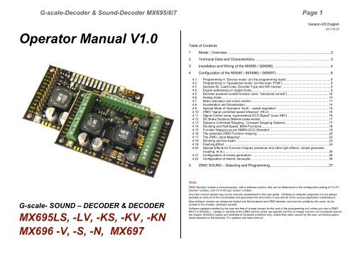
G-<strong>scale</strong>-Decoder & Sound-Decoder MX695/6/7 Page 1<br />
<strong>Operator</strong> <strong>Manual</strong> <strong>V1.0</strong><br />
Table of Contents<br />
Version-US English<br />
2011 05 30<br />
1 Model - Overview ..................................................................................................... 2<br />
2 Technical Data and Characteristics .......................................................................... 3<br />
3 Installation and Wiring of the MX695 / (MX696) ....................................................... 4<br />
4 Configuration of the MX695 / (MX696) / (MX697) ..................................................... 8<br />
4.1 Programming in “Service mode” (on the programming track) ................................................... 8<br />
4.2 Programming in “Operational mode” (on-the-main “PoM”) ........................................................ 8<br />
4.3 Decoder-ID, Load-Code, Decoder-Type and SW-Version ........................................................ 9<br />
4.4 Engine addresse(s) in digital mode ............................................................................................ 9<br />
4.5 Decoder powered consist function (also: "advanced consist”) ................................................ 10<br />
4.6 Analog mode ............................................................................................................................ 10<br />
4.7 Motor activation and motor control ........................................................................................... 11<br />
4.8 Acceleration and Deceleration: ................................................................................................ 14<br />
4.9 Special Mode of Operation “km/h – speed regulation” ............................................................ 15<br />
4.10 ZIMO “signal controlled speed influence” (HLU)...................................................................... 15<br />
4.11 Signal Control using “asymmetrical DCC-Signal” (Lenz ABC) ................................................ 16<br />
4.12 DC Brake Sections (Märklin brake-mode) ............................................................................... 17<br />
4.13 Distance Controlled Stopping - Constant Stopping Distance .................................................. 17<br />
4.14 Shunting and Half-Speed, MAN-Functions: ............................................................................. 18<br />
4.15 Function Mapping as per NMRA-DCC-Standard ..................................................................... 19<br />
4.16 The extended ZIMO Function mapping ................................................................................... 20<br />
4.17 The ZIMO „Input-Mapping“....................................................................................................... 23<br />
4.18 Dimming and low beam ............................................................................................................ 23<br />
4.19 Flashing-Effect ......................................................................................................................... 24<br />
4.20 Special Effects for Function-Outputs (american and other light effecrs, smoke generator,<br />
coupling, et al.) ......................................................................................................................... 25<br />
4.21 Configuration of smoke generators .......................................................................................... 26<br />
4.22 Configuration of electric decoupler .......................................................................................... 26<br />
5 ZIMO <strong>SOUND</strong> – Selecting and Programming ......................................................... 27<br />
G-<strong>scale</strong>- <strong>SOUND</strong> – <strong>DECODER</strong> & <strong>DECODER</strong><br />
MX695LS, -LV, -KS, -KV , -KN<br />
MX696 -V, -S, -N, MX697<br />
Note<br />
ZIMO Decoder contain a microprocessor, with a software version, that can be determined in the configuration setting of CV # 7<br />
(version number), and CV # 65 (sub version number).<br />
Any then current version may not be correctly represented in this user guide. Similarly to computer programs it is not always<br />
possible to verify all of the functionality and guarantee that all function in any and all of the various application combinations.<br />
New software version can always be loaded into the hardware and ZIMO decoder can even be update by the users. As described<br />
in the chapter „Software-Update“.<br />
Software updates installed by the user are free of charge (except for the cost of the programming unit unless you own a ZIMO<br />
MX10 or MX32ZL), Update or rebuilds at the ZIMO service center are typically not free of charge and are not considered warrantee<br />
repairs. Warranty repairs are restricted to hardware problems only, unless they were caused by the user connecting operational<br />
elements to the board(s). For updates visit www.zimo.at !
Page 2 G-<strong>scale</strong>-Decoder & Sound-Decoder MX695/6/7<br />
1 Model - Overview<br />
The MX695 G-<strong>scale</strong> decoder is available in three different models of which 4 are with sound. In<br />
addition there also will be special versions with adapted functionality (i.e. adapted number of<br />
available outputs.).<br />
ZIMO Decoders have the NMRA-DCC data format implemented and therefore operate with ZIMO<br />
DCC systems as well as with other DCC compatible systems., including systems based on the<br />
MOTOROLA-Protocol (MM) for Märklin and other MOTOROLA based command stations. ZIMO<br />
Decoders work also in Analog Mode ((DC) –(Model railroad -Transformers, PWM- and Laboratory<br />
power supplies, as well as AC – Analog Mode (Transformers with high-voltage-impulse for directional<br />
control).<br />
51 x 40 x 12 mm<br />
51 x 40 x 12 mm<br />
MX695KN<br />
MX695KN<br />
Non-Sound-Decoder with screw terminals<br />
Non-Sound-Decoder with screw terminals<br />
20 screw terminals (1 x 8 and 1 x 12)<br />
8 function outputs (including headlights)<br />
1 low-voltage output: 10 V<br />
4 Servo-Outputs (ea. 3-pin: control, ground, + 5 V)<br />
2 Variable controls (loudness, low-voltage adjustment)<br />
MX695K …<br />
Sound-Decoder with screw terminals<br />
55 x 26 x 16 mm<br />
MX695KV<br />
MX695KS<br />
Full Edition: 36 screw terminals<br />
14 function outputs (including headlights)<br />
1 special out for smoke generator fan<br />
3 low voltage outputs: 5 V, 10 V, variable<br />
4 Servo-Outputs (ea. 3-pin: control, ground, + 5 V)<br />
2 variable controls (loudness, low voltage adjustment)<br />
1 connection for electronic flywheel (capacitor input)<br />
Reduced.: 28 screw terminals (2 x 12 and 1 x 4)<br />
8 function outputs (including headlights)<br />
1 low voltage output: 10 V<br />
1 connection for electronic flywheel (capacitor input)<br />
MX696 …<br />
MX696V<br />
MX696S<br />
(Sound-) Decoder with style & connection technology as the<br />
MX690 / MX69<br />
Full edition:<br />
reduced:<br />
2 16-pin connectors &<br />
4 screw terminals<br />
14 function-outputs (including headlights)<br />
1 low-voltage output: variable (1,2 V - track)<br />
4 Servo-outputs (control line)<br />
1 16-pin connectors & 1 10-pin connectors &<br />
4 screw terminals<br />
8 funtion-outputs (including headlights)<br />
MX695L …<br />
Sound-Decoder with pin connectors<br />
MX696N<br />
non-sound: 1 16-pin connectors &<br />
4 screw terminals<br />
8 function-outputs (including headlights)<br />
MX695LV<br />
Full Edition:<br />
3 pin connectors, ea 12-pins<br />
14 function outputs (including headlights)<br />
1 special out for smoke generator fan<br />
3 low voltage outputs: 5 V, 10 V, variable<br />
4 Servo-Outputs (ea. 3-pin: control, ground, + 5 V)<br />
2 variable controls (loudness, low voltage adjustment)<br />
1 connection for electronic flywheel (capacitor input)<br />
MX697<br />
To be announced<br />
MX695LS<br />
Reduced:<br />
2 pin connectors, ea. 12-pin (matching ESU-interface)<br />
4 soldering pads for additional connections<br />
8 function outputs (including headlights)<br />
1 low voltage output: 10 V<br />
1 connection for electronic flywheel (capacitor input)
G-<strong>scale</strong>-Decoder & Sound-Decoder MX695/6/7 Page 3<br />
2 Technical Data and Characteristics<br />
.<br />
Track Voltage using digital control (DCC) ........................................................................ 10 - 30 V<br />
Electric strength (peak) in analog mode (High voltage pulse for direction reversal) ................ 35 V<br />
Threshold voltages in analog mode - see below !<br />
Maximum continuous motor output = maximum continuous total output ..................................... 6 A<br />
Maximum peak current (Motor only or total) ............................................................................. 10 A<br />
Number of function outputs .............................................. MX695KV, MX695LV 14<br />
MX695KS, MX695LS, MX695KN ... 8<br />
Maximum continuous total output per function group ................................................................ 2 A<br />
Maximum continuous output for low-voltage functions (5 V, 10 V, adjustable) ................. each 1 A<br />
Voltage range for adjustable low-voltage functions (MX695KV, -LV) .............................. 1,5 to 16 V<br />
Maximum current at special output for Smoke-Ventilator (5 V - Motor) with brake function<br />
200 mA<br />
Storage capacity for sound samples ................................................................................... 32 Mbit<br />
Sample rate depending on individual characteristics of the selected sound samples … 11 or 22<br />
kHz<br />
Numer of simultaneously playable sound channels ....................................................................... 6<br />
Sound-amplifier output at 4 Ohm ................................................................................ Sinus 10 W<br />
Impedance of speakers ............................................................. 8 Ohm, 2 x 8 Ohm parallel, 4 Ohm<br />
Externally connection for electronic flywheel . ....................................................... Load voltage 17 V<br />
for standard capacitor ..................................... >= 20 V, any capacity<br />
gold-caps (pack with 7 pieces each 2,5 V - in series) >= 17 V, max. 1 F<br />
Rechargeable battery (only with special circuitry) ........... 14,4 V pack<br />
charge current for external energy storage ............................. 80 mA<br />
Analog mode (continuous current, alternating current)*) Threshold voltage headlights ......... ca. 4 V<br />
Threshold voltage Sound ............... ca. 5 V<br />
Threshold voltage motor-activation ca ... 6 V<br />
Operating temperature ................................................................................................ - 20 to 100 o C<br />
Dimensions (L x W x H including pinss) **)<br />
MX695KV, -KS ............ 50 x 40 x 14 mm<br />
(L x W x H including screw terminals) MX695LV ..................... 50 x 40 x 14 mm<br />
(long plugin terminals for ESU-loco board) MX695LS ...................... 50 x 40 x 20 mm<br />
MX696 .................... 55 x 26 x ca. 16 mm<br />
*) Actual analog-characteristics strongly dependent on vehicle model and engine (transformer output<br />
voltage may fail due to overload)<br />
**) Length given without break-away mounting brackets; increase the length by 2 x 6 mm<br />
OVERLOAD PROTECTION<br />
The motor and function outputs of the ZIMO large-<strong>scale</strong> decoders are designed with large reserve<br />
capacities and are additionally protected against over-currents and short circuits. Automatic<br />
shutoff will occur in case of overload followed by automatic reboots. (A Common side effect is<br />
blinking lights).<br />
These safety precautions do not mean that the decoder is indestructible. Please pay attention to the<br />
following:<br />
Faulty decoder hook-up (mixed up connection wires) and improper electric connections between the motor<br />
terminal and chassis are not always recognized and can lead to output driver damage or even total destruction<br />
of the receiver.<br />
Unsuitable or defective motors (e.g. with short-circuited turns or collectors) are not always recognizable by<br />
their high consumption of electricity (only peaks may register) and can lead to decoder damage, sometimes<br />
long term effects can cause output driver defects.<br />
The decoders output drivers (for the motor and function outputs) are not only at risk through over-current but<br />
also through voltage spikes as they are delievered from the motor and other inductive consumers. Depending<br />
on track voltage, such spikes can reach several hundred volts and are absorbed by special protection<br />
circuits inside the decoder. The capacity and speed of such elements is limited and so unnecessarily high<br />
track voltage should not be used. Never use a higher voltage than recommended for a particular vehicle. Only<br />
in exceptional cases should the ZIMO adjustable range (up to 24 V) be utilized.<br />
THERMAL PROTECTION<br />
All ZIMO decoders come equipped with a sensor that detects the actual temperature. Once the<br />
maximum permissible value (ca. 100 o C on the circuit board) has been reached, power to the<br />
motor will be shut off. Rapidly flashing headlights (at ca. 10 Hz) will signal that a shut-off has occurred.<br />
Motor operation will resume automatically after a drop in temperature of about 20 o C, typically<br />
after 30 to 60 sec.<br />
SOFTWARE UPDATE<br />
ZIMCO decodes are designed so that software updates can be completed by the user. This requires<br />
a device with an update function (ZIMO decoder update module MXDECUP, or MXULF,<br />
or “central system cab“ MX31ZL/MX32ZL, or command station MX10).The update itself is carried<br />
out via a USB stick (MXULF, MX31ZL, MX32ZL, MX10) or via a computer with the “ZIMO<br />
Sound Programmer” ZSP software or “ZIMO Rail Center” ZIRC software.<br />
There is no need to remove the decoder; the locomotive does not need to be opened; it can be<br />
placed onto the update-track (connected to the update-device) without any changes and can<br />
then be updated via a USB stick or a computer.<br />
Note: Locomotive accessories that are directly connected to a track (not controlled by the decoder) may interfere<br />
with the update; in that case the locomotive will have to be opened and removed from the track.<br />
ZIMO ELEKTRONIK Schönbrunner Straße 188, 1120 Wien, Österreich www.zimo.at<br />
office@zimo.at<br />
Tel ++43 (1) 81 31 007 0<br />
RailCom is a trademark of Lenz Elektronik GmbH
Page 4 G-<strong>scale</strong>-Decoder & Sound-Decoder MX695/6/7<br />
3 Installation and Wiring of the MX695 / (MX696)
G-<strong>scale</strong>-Decoder & Sound-Decoder MX695/6/7 Page 5<br />
3.1 Track and Motor(s)<br />
Find or make room for the<br />
decoder in the engine in order<br />
to accommodate the decoder<br />
easily.<br />
All direct connections that<br />
are present in the original<br />
wiring configuration between<br />
the power pick-ups (wheels<br />
& pickup shoes) and the motor(s)<br />
must be separated.<br />
Even the headlights and<br />
other additional accessories<br />
must be completely isolated.<br />
Connect track (wheel and<br />
pick-up shoes) and motor to<br />
their positions on the screw<br />
treminals as shown in the illustration.The<br />
sometimes<br />
present second connection<br />
points can, but don’t have to<br />
be used.<br />
Practically all common DC-motors used in your models (commercial and kitbashed) can be utilized.<br />
In case that more than one motor is present in the vehicle, they will be parallel connected to<br />
the decoder. The parallel connection will result in an automatic synchronization if all motors are<br />
identical and use identical gear boxes. The MX695 is typically powerful enough to drive both<br />
motors.<br />
See Configuration (CV’s) for motor-control!<br />
3.2 Speaker and Cam Sensor, Volume Control<br />
Any 4 Ohm and 8 Ohm speakers can be<br />
used, or several speakers can be used<br />
in a parallel/serial connection as long as<br />
the total impedance is not less than 4<br />
Ohm.<br />
The sound amplifier for the MX695<br />
works with a voltage of 10.8 V and has a<br />
sinus output of 12 Watt with a 4 Ohm<br />
speaker; with an 8 Ohm speaker it’s<br />
less, aprox. 6 Watt.<br />
If you connect in parallel tweeters to the<br />
main speaker then they shall be connected<br />
via a crossover (for instance 10<br />
uF capacitor).<br />
Naturally the speaker (or several speakers<br />
together) must be able to withstand<br />
the output.This means that the volumne<br />
must be cut back accordingly on lower<br />
rated speakers.<br />
The “virtual chuff sensor technology” is<br />
very sophisticated and equivalent to<br />
physical chuff sensors.Therefore there is<br />
no advantage installing a cam sensor<br />
(for chuff synchronization to the wheel<br />
rotation).<br />
In case a “real” chuff sensor is desired, a mechanical contact, a photo transistor, or a hallsensor<br />
can be connected to the gate input “IN 3”. The particular element must create a lowohm<br />
connection (meaning < 10 K) between the gate input and GROUND when it generates<br />
impulses that are synchronized to the wheel rotation.<br />
The volume can be adjusted by an internal and/or external potetniomenter in addition to the<br />
software control via CV#266. The manual volume control is highly desired for Analog operations.<br />
When an external potentiomer (100 K, preferably type audio/logarithmically) is inserted, the<br />
pontentiometer on the circuit board neds to be turned up to full volume (counter clockwise)<br />
unless the internal pontentiometer is setting a limit for maximum volume to protect a lower<br />
wattage speaker.
Page 6 G-<strong>scale</strong>-Decoder & Sound-Decoder MX695/6/7<br />
3.3 Function-Equipment and Function-Low Voltage<br />
“Function Equipment” is all equipment that is connected to the function-outputs FLf, FLr, and<br />
FO1 (FO1)...FO12 (FO12). This is mostly lighting equipment (light bulbs and LEDs) but also<br />
operating magnets, small motors, relays, etc.<br />
See Chapter Decoder Configuration (CV’s) for “function mapping”, function effects electric<br />
coupling (Krois system, Heyn) etc.<br />
3.4 Special Connection for Smoke Fan<br />
This output is used to power the fan motor for chuff or load synchronized applications.<br />
Those smoke units are either already available in the locomotive or can be additionally purchased.<br />
What is distinct about this output (this is different from “normal” function outputs) is the possibility<br />
to apply a brake to the fan motor. This stops the motor immediately after the motor<br />
impulse has stopped and therefore improves the smoke effect.<br />
The output is designed for a 5 V motor and up to 100 m A constant-current ( the starting current<br />
can be much higher).<br />
Note: Only available in the MX695KV, MX695LV, and other ..V – type models !<br />
3.5 Servos<br />
Each function-equipment (lamps, groups of lamps, etc.) is switched between the corresponding<br />
function-output (minus) and one of up to four positive voltage supply sources (plus).<br />
- Positive terminal – full track voltage: the rectified constant track voltage; which is more or less<br />
instable, depending on the stabilizing on the quality of the digital-command station/booster.<br />
This means the voltage fluctuates with the track power.<br />
000- Low Voltage - 10 V: this is the voltage which is generated in the decoder mainly for the<br />
sound amplifier. ATTENTION: too high or unstable usage by the function equipment from this<br />
voltage source can impair the sound quality.<br />
- Low Voltage - 5 V: this voltage is used for operating the Servos and is also available for the<br />
function equipment such as the typical 5 V light bulbs.<br />
Note: Only available in the MX695KV, MX695LV, and other ..V – type models !<br />
- Variable low voltage: using the potentiometer on the decoder circuit board, or if desired<br />
using a controller (100K lin) externally connected to the three solder pads, the function voltage<br />
can be selected between ca. 1.5 V and the full track voltage.<br />
Note: Only available in the MX695KV, MX695LV, and other ..V – type models !<br />
Note: The usage of a true low voltage source is preferred over PWM dimming<br />
(CV # 60). PWM uses full voltage impulse with corresponding duty cycle which<br />
can cause damage to light bulbs if the PWM cycle is 3 or more (LEDs are not effected).<br />
MX695 offers 4 connections for standard<br />
Servos, that can be used for de-couplers,<br />
pantos and other mechanical operations.<br />
For each Servo connection there is a separate<br />
control wire available while the power (+<br />
5 V, Ground) is the same for all.<br />
ATTENTION: Although different<br />
brands of Servos have the three<br />
wires, the order and color of the<br />
wires is not always the same.<br />
See chapter dealing with decoder configurations<br />
regarding the order and adjustment of<br />
the Servos.<br />
Note:<br />
5 V supply for servos is only available in the MX695KV, MX695LV, and other<br />
V – type models!<br />
The control wires are usable for all versions of the MX695, so you might have to supply +5 V<br />
external of the decoder.
G-<strong>scale</strong>-Decoder & Sound-Decoder MX695/6/7 Page 7<br />
3.6 Control Input<br />
In addition to “IN 3” (see chapter 3.2,<br />
Speakers and Cam Sensor) there are<br />
two more inputs (“IN 1” and “IN 2”).<br />
You can use for example reed contacts<br />
connectedto these function inputs<br />
for generating sounds, e.g. bell<br />
and whistle. This is very desired for<br />
analog operations, but can be useful in<br />
DCC too, e.g. curve wheel squeal to<br />
be automatically triggered when the<br />
trains enters a cruve.<br />
There control inputs act electrically<br />
similar.<br />
See chapter regarding decoder configuration<br />
(CV’s), especially covering sound.<br />
Generally the effectiveness of the electronic flywheel increases with the capacity; starting at<br />
approximately 1000 uF (uF = microFarad) an effect is noticable, approximately 100,000 uF<br />
are advisable for large engines as long as the space is available; Gold-Cap arrangements<br />
with more F (Farad) are even better. Capacities that are too large, however, do have a<br />
drawback, the time for charging becomes very long. This is why ZIMO advises no more than<br />
1 F for Gold-Caps (this is based on the overall series connection of 7 elements with 2.5 V<br />
each. A single Gold-cap has baout 5F).<br />
Charging current for external capacitor is approx. 80 mA; this means full charge of a 10,000<br />
uF – capacitor is about 5 sec, in case of a 1 F Gold-Cap the charging time is.~ 3 min. Unlike<br />
a rechargable battery (rechargeable), a capacitor only offers the maximum current once fully<br />
charged!<br />
The MX695 has been developped that external capacitors DO NOT cause problems during<br />
decoder programming, and during software updates, and neither for the ZIMO train number<br />
identification or for RailCom.<br />
The installation of a battery instead of a capacitor is currently only recommended for professionals<br />
(experienced electronic hobbyists); it is important that a total discharge is prevented<br />
after a loss of track power.<br />
Suggestion: a relay with holding current supplied by track voltage, with holding<br />
capacitor, which disconnects the wires to the battery about 1 min. after loss of<br />
track power.<br />
3.7 Electronic Flywheel<br />
With the help of a capacitor<br />
(standard or Gold-Cap) or a<br />
re-chargable battery you<br />
can:<br />
- the driveability on dirty<br />
tracks (or with dirty<br />
wheels) is improved,<br />
- the flashing of lights due to<br />
loss of contact (frogs, ...) is reduced,<br />
- avoid that trains get stuck, while<br />
driving slow or on unpowered<br />
frogs, if used especially with the configuration<br />
feature “Prevention of stopping on current-less<br />
areas” *) which is available in all ZIMO decoders.<br />
- the energy loss due to “RailCom-gaps” and “HLU-gaps” is compensated<br />
and the accossciated motor sounds are reduced. At the same time the<br />
RailCom signal quality (= readout quality) is improved.<br />
3.8 The SUSI Interface<br />
The “SUSI” interface, developed by Dietz, defines the connection to additional modules,<br />
mostly sound, which in untypicall when sound decoders asre used.<br />
Currently there are hardly any SUSI modules available except<br />
for the sound modules which are rarely<br />
used with a sound decoder such as the MX695.<br />
On one hand the interface is designated as a reserve<br />
for possible panto circuit boards and similar<br />
equipment (possibly from ZIMO) and on the<br />
other hand ...<br />
... for fast charging of sound projects (the way<br />
ZIMO has them factory-provided; in this case it is<br />
not about the SUSI protocol, but about the much<br />
faster communication)<br />
See the chapter regarding decoder configuration<br />
(CV’s), especially covering sound.<br />
*) In case of loss of power (due to dirt on the tracks or on unpowered frogs) the decoder will automatically assure<br />
that the vehicle continues driving even if it is supposed to come to a halt due to a brake application. Only<br />
once the track power connection has been re-establised will the train stop and check whether the connection<br />
is still present while stopped (otherwise a normal short adancement follows)
Page 8 G-<strong>scale</strong>-Decoder & Sound-Decoder MX695/6/7<br />
4 Configuration of the MX695 / (MX696) / (MX697)<br />
ZIMO decoder can be programmed using<br />
- “Service mode” (on the programming track) addressed (= registering the vehicle address) and<br />
programming (writing und read-out of the CV’s – configuration variables) or,<br />
- “Operational mode” (“Programming-on-the-main” = “PoM”);<br />
programming the CV’s in “operational mode” is always possible, the verification of the<br />
programming and the read-out ,however, only when the digital system understands “RailCom”.<br />
4.1 Programming in “Service mode” (on the programming<br />
track)<br />
In order to program, the programming block must be lifted, so<br />
CV # 144 = 0 or = 128 (128: in this case programming is enabled, but SW updates are blocked)<br />
CV # 144 = 0 is the decoders default, but some sound projects activate the programming block so<br />
that accidential changes are prohibited. Always check CV# 144 in particular if some programming<br />
attempts already failed.<br />
The confirmation of programing steps as well as CV read-out are accomplished with power bursts.<br />
The decoder accomplishes this through a short activation of headlights and motor. Should there<br />
be no or too little current (e.g. they are disconnected) then the confirmation and the read-out are<br />
not possible.<br />
In that case it might be possible to configure CV #112, Bit 1 to generate an alterntive metthod, the<br />
high feequency-impuls activation of the power circuit for the motor output. The success of this<br />
method depends on the central station in use.<br />
CV Designation Range Default Description<br />
# 144<br />
Programming and<br />
Update Lock<br />
Note: The program lock<br />
in CV # 144 hase no influence<br />
for CV # 144 itself;<br />
otherwise it would<br />
be impossible to lift the<br />
lock.<br />
Bits<br />
6, 7<br />
0<br />
or<br />
255<br />
= 0: Unrestricted CV programming,<br />
Bit 6 = 1: No programming possible in<br />
service mode: protection against<br />
unintentional programming.<br />
Note: “on-the-main” programming is still<br />
possible<br />
Bit 7 = 1: Software updates normally executed with<br />
the<br />
MX31ZL or future devices are blocked.<br />
4.2 Programming in “Operational mode” (on-the-main “PoM”)<br />
Programming in “Operational mode”, otherwise known as “Programming-on-the-main” = PoM<br />
“Programming-on-the-fly”.<br />
According to the current NMRA-DCC standard, only CV-programming and read-outs are possible<br />
on the main track but not the ability to assign a new address. Specific command stations<br />
(such as ZIMO beginning with generation MX10/MX32) allow with “bi-directional communication”<br />
also the modification of the address.<br />
All ZIMO decoders are equipped with bi-directional communication according to the “RailCom”<br />
operation, this way the usage of a corresponding central stations (ZIMO MX31ZL and all equipment<br />
starting with the MX 10/MX32 generation) and therefore comfirm the completed programming<br />
as well as enable read-out fo CV valaues in “operational mode”, on the main track. For this<br />
“RailCom” must be activated. This is the case when,<br />
CV # 29, Bit 3 = 1 AND CV # 28 = 3<br />
Even though this is the factory setting, in some sound projects or OEM-CV-sets, however, this<br />
capability might be turned off and must be activated again.<br />
CV Designation Range Default Description<br />
# 28<br />
# 29<br />
RailCom Configuration<br />
Base Configuration<br />
Configuration data<br />
0 - 3 3<br />
0 - 63<br />
14 =<br />
0000 1110<br />
also Bit 3 =<br />
1<br />
(„RailCom“<br />
on)<br />
Bit 0 - RailCom Channel 1 (broadcast)<br />
0 = off 1 = on<br />
Bit 1 - RailCom Channel 2 (Daten)<br />
0 = aus 1 = eingeschaltet<br />
Bit 0 – train direction<br />
0 = normal, 1 = reversed<br />
Bit 1 - number of speed steps<br />
0 = 14, 1 = 28 Fahrstufen<br />
Bit 2 - automatic detection of analog mode<br />
0 = off, 1 = on<br />
Bit 3 - RailCom (“bi-directional communication”)<br />
0 = off 1 = on<br />
Bit 4 – individual speed table<br />
0 = three point-cl. according to CV # 2, 5, 6<br />
1 = free characterisitc according to CV # 67 …<br />
94<br />
Bit 5 – Selection of vehicle address (DCC)<br />
0 = primary address as per CV # 1<br />
1 = ext. address as per CV’s # 17+18<br />
# 112<br />
Special ZIMO configuration<br />
bits<br />
0 - 255<br />
4 =<br />
00000100<br />
also Bit 1 = 0<br />
(normal)<br />
Bit 1 = 0: Normal „service mode“ acknowledgement<br />
by actuating motor and headlights.<br />
= 1: High frequency current impulses as addi<br />
tional acknowledgement, whenn motor/lights<br />
are not enough<br />
Bit 2 = 0: loco number recognition off<br />
etc,<br />
Note:<br />
Greyed-out bits in the CV tables indicate capabilities that are not utilized in the<br />
given chapter.
G-<strong>scale</strong>-Decoder & Sound-Decoder MX695/6/7 Page 9<br />
4.3 Decoder-ID, Load-Code, Decoder-Type and SW-<br />
Version<br />
CV Designation Range Default Description<br />
# 250,<br />
251,<br />
252,<br />
253<br />
Decoder-ID<br />
includes also a<br />
code (in CV # 250)<br />
for the decoder-type<br />
read only -<br />
The decoder ID (serial number) is automatically entered<br />
during production: the first byte denotes the decoder<br />
type; the three other bytes contain the serial<br />
number.<br />
The decoder ID will be required during registering at<br />
the central station as well as in combination with the<br />
load code for paid sound apps.(see CV’s # 260 bis<br />
263).<br />
4.4 Engine addresse(s) in digital mode<br />
The default setting for engine addresses is usually Address 3, meaning CV # 1 = 3, for the DCC<br />
mode as well as the MM mode. Operating on this address is possible but it is advisable to<br />
choose a new permanent address relatively quickly.<br />
In the DCC mode the address space exceeds the range of a single CV, namely up to 10239. For<br />
addresses starting at 128, the two CV’s # 17 + 18 are used. In CV #29, Bit 5 determines if the<br />
“short” addess in CV # 1 is valid or the “long” addess in CV’s # 17 + 18 is used.<br />
Modern digital systems (possibly with the exception of very old or simple products)<br />
excecute the particular CV’s and the Bit 5 in CV # 29 when writing the address<br />
(= addressing) to the decoder, and the user does not have to deal with<br />
the coding himself.<br />
# 260,<br />
261,<br />
262,<br />
263<br />
# 8<br />
# 7<br />
Load-code<br />
for<br />
"paid-sound” apps<br />
Manufacturer ID<br />
and<br />
HARD RESET<br />
with CV # 8 = “8“<br />
bzw. CV # 8 = 0<br />
or<br />
LOADING<br />
of special CV sets<br />
SW version number<br />
See also CV # 65<br />
Sub-version number<br />
and<br />
Indirect Programming<br />
Temporary register when<br />
programming with a<br />
“Lokmaus-2” and simmilar<br />
low level systems<br />
- -<br />
Read only<br />
read-out always<br />
shows<br />
“145”, which<br />
is ZIMO‟s assigned<br />
number<br />
Pseudo-<br />
Programm.<br />
see description<br />
Read only<br />
Pseudo-<br />
Programm.<br />
see description<br />
on right<br />
145<br />
( = ZIMO)<br />
-<br />
ZIMO sound decoders can be preinstalled with a<br />
load-coad for an additional charge. Therefore they<br />
can accept a a paid-sound app from one given provider.<br />
Otherwise the “load code” must be obtained<br />
and installed after purchase.<br />
See ZIMO’s Website www.zimo.at or ZIRC.<br />
Read-out of this CV is always the NMRA assigned<br />
manufacturer number; for ZIMO “145” (”10010001”).<br />
Additionally this CV is used during “pseudoprogramming”<br />
to trigger reset operations.<br />
“Pseudo-programming” means: programmed value is not<br />
stored, instead the value triggers a definite action.<br />
CV # 8 = “8” HARD RESET (NMRAstandardized);<br />
all CV’s default back to the last CV-Sets used<br />
or (if none were previously activated) the<br />
default value, as described in this CV-chart.<br />
Further possibilities: see chapter “CV Sets” !<br />
The read-out of this CV is the version number of the<br />
currently loaded decoder software (firmware).<br />
At the same time this CV is used via “pseudo programming“<br />
to program a decoder of a digital system<br />
with a limited handling capacity for higher numbers<br />
(typ. example: old Lokmaus):<br />
First digit = 1: subsequent program value + 100<br />
= 2: ... + 200<br />
Second digit = 1: subsequent CV-number + 100<br />
= 2: … + 200<br />
cont. = 9: … + 900<br />
Third digit = 0: indirect programming for one operation<br />
= 1 … until power down<br />
CV Designation Range Default Description<br />
# 1<br />
# 17<br />
+<br />
18<br />
# 29<br />
Primary “short”<br />
address<br />
Extended Address<br />
Base Configuration<br />
DCC:<br />
1 - 127<br />
MM:<br />
1 - 80<br />
128<br />
-<br />
10239<br />
0 - 63<br />
3<br />
0<br />
14 =<br />
0000 1110<br />
also Bit 5 =<br />
0<br />
(“short”<br />
address)<br />
The primary “short” address (DCC, MM)<br />
In DCC mode:<br />
According to CV # 1, the primary short address is only<br />
valid if CV # 29 (basic settings), Bit 5 = 0.<br />
Alternatively, the address according to CV # 17 + 18 is<br />
valid, so when CV # 29, Bit 5 = 1.<br />
The primary long address (DCC), when an address<br />
starting at 128 is chosing.<br />
The address according to CV’s # 17 + 18 is valid<br />
when CV # 29 (basic setting), Bit 5 = 1.<br />
Bit 0 – Train direction:<br />
0 = normal, 1 = reversed<br />
Bit 1 - Number of speed steps:<br />
0 = 14, 1 = 28 speed steps<br />
Bit 2 - automatic detection of analog mode<br />
0 = off, 1 = on<br />
Bit 3 - RailCom (“bi-directional communication“)<br />
0 = off 1 = activated<br />
Bit 4 – Individual speed table<br />
0 = three step prog. according to CV # 2, 5, 6<br />
1 = free speed table according to CV # 67 …<br />
94<br />
Bit 5 - Selection of primary address (DCC)<br />
0 = primary "short” address as per CV # 1<br />
1 = ext. (“long”) address as per CV’s # 17+18<br />
# 65<br />
SW Sub-version num.<br />
See also CV # 7<br />
Version number<br />
Read only -<br />
In case the version in CV # 7 is accompanied by a<br />
subversion, refer to CV # 65<br />
The complete description of a software version is<br />
comprised of CV’s # 7 + # 65 (for instance 28.15).
Page 10 G-<strong>scale</strong>-Decoder & Sound-Decoder MX695/6/7<br />
4.5 Decoder powered consist function (also: "advanced<br />
consist”)<br />
Consist operations means operating two or more vehicles (mostly mechanically coupled) with<br />
the same speed which can either<br />
• be organized through the digital system (common in ZIMO, does not impact the decoder’s<br />
CV’s), or<br />
• can be regulated by the following CV’s of the decoder, which can be individually programmed,<br />
or handled by the central station (often found in American system).<br />
This chapter only deals with the second case, the decoder controlled consist functions!<br />
CV Designation Range Default Description<br />
# 19<br />
# 21<br />
,<br />
# 22<br />
Consist address<br />
Consist Functions<br />
F1 - F8<br />
Functions<br />
F0 forward, backwards<br />
in consist operation<br />
Consist address active<br />
for FL<br />
4.6 Analog mode<br />
0 - 127 0<br />
0 - 255 0<br />
0 - 3 0<br />
Alternative addresses for the consist function, also referred<br />
to as traction function.<br />
If CV # 127 > 0: the speed is controlled via the consist<br />
address (and not via the single addesses in CV # 1 or #<br />
17 + 18); these functions are selectively controlled via<br />
the consist address or the single address; see CV’s #<br />
19 + 20.<br />
Selection of the functions, which should operate with<br />
the consist address in the consist function.<br />
Bit 0 = 0: F1 operated via a single address<br />
= 1: …. via a consist address<br />
Bit 1 = 0: F2 operated via a single address<br />
= 1: …. via a consist address<br />
………. F3, F4, F5, F6, F7<br />
Bit 7 = 0: F8 operated via a single address<br />
= 1: …. via a consist address<br />
Select whether headlights are controlled via consist address<br />
or single address.<br />
Bit 0 = 0: F0 (forward) operated via a single address<br />
= 1: …. via a consist address<br />
Bit 1 = 0: F0 (backward) operated via a single address<br />
= 1: …. via a consist address<br />
ZIMO decoders (all types) are very well suited for all conventional layouts (with model train transformers,<br />
PWM cruising equipment, etc.) as well as analog continuous currents and analog alternating<br />
currents (Märklin, also with high voltage pulse for direction reversal).<br />
In order to enable the analog mode set:<br />
CV # 29, Bit 2 = 1<br />
Although this (CV # 29 = 14, also auch Bit 2 = 1) is a default setting, in some sound projects the<br />
analog mode has been deactivated. Therefore if the analog mode is not functioning it is useful to<br />
double check whether is was deactivated in the factory settings.<br />
The new large <strong>scale</strong> decoders (MX695/6/7) are well suited for analog operation because they<br />
can start lights, sound and the motor at very low voltage enabled by "raising” the track voltage internally<br />
to a certain degree. See the chapter titled Technical Data. Stepped thresholds control<br />
that first only the headlights will work, then once more voltage is present the sound will start and<br />
finally the motor.<br />
The actual performance in analog mode, however, is strongly dependent on the vehicle. If a weak transformer<br />
is used the track power can break down when the decoder begins the consumption of electricity and sufficient<br />
electricity is not available. If worst come to worst, it will oscillate between operating and not operating.<br />
There are some programming possibilities for the motor control and function outputs in analog mode. The CV’s<br />
can only be programmed or read in digital mode, with the help of a digital system or programming equipment.<br />
CV Designation Range Default Description<br />
# 13<br />
# 14<br />
,<br />
# 29<br />
Analog Functions<br />
F1-F8<br />
Analog functions<br />
and<br />
Regulated Analog<br />
Base Functions<br />
F0 forward, backwards<br />
in consist operation<br />
Consist address active<br />
for FL<br />
0 - 255 0<br />
0 - 255 64<br />
0 - 3 0<br />
Selects function outputs, F1 to F8, which should be “on”<br />
in analog mode. Each bit equals one function; Bit 0 =<br />
F1, Bit 1 = F2 ……….. Bit 6 = F7, Bit 7 = F8.<br />
Bits 0 to 5: Choose function outputs F9 to F12 as well as<br />
HLr and HLf that should be “on” in analog mode. Each<br />
bit equals one function (Bit 0 = front headlight, Bit 1 =<br />
rear headlight, Bit 2 = F9…Bit 5 = F12).<br />
Bit 6 = 1: Analog operation without applying<br />
CV #3 and CV #4 defined momentum.<br />
Bit 6 = 0: Analog operation with CV #3 and CV #4<br />
defined momentum.<br />
Bit 7 = 0: unregulated DC operation<br />
Bit 7 = 1: regulated DC operation<br />
Bit 0 – Train direction:<br />
0 = normal, 1 = reversed<br />
Bit 1 - Number of speed steps:<br />
0 = 14, 1 = 28 speed steps<br />
Bit 2 - automatic detection of analog mode<br />
0 = off, 1 = on<br />
Bit 3 - RailCom (“bi-directional communication“)<br />
0 = off 1 = activated<br />
Bit 4 – Individual speed table<br />
0 = three step prog. according to CV # 2, 5, 6<br />
1 = free speed table according to CV # 67 … 94<br />
Bit 5 - Selection of primary address (DCC)<br />
0 = primary "short” address as per CV # 1<br />
1 = ext. (“long”) address in CV’s# 17+18<br />
Note: Other settings, than the decoders default settings, can be active because of<br />
the currently loaded sound project. This is particularly true for the motor control<br />
settings that are often turned on by the sound project. Those configurations, however,<br />
only work well for controllers with a smooth output voltage (like LGB 50080).<br />
It is advisable to turn off motor control if you use half-wave track voltages.
G-<strong>scale</strong>-Decoder & Sound-Decoder MX695/6/7 Page 11<br />
4.7 Motor activation and motor control<br />
The Speed Curve<br />
There are two ways of programming the speed curve:<br />
CV # 29, Bit 4 = 0: three-step programming (defined by 3 CV’s)<br />
... = 1: 28-step programming (defined by 28 CV’s)<br />
Three-step programming: By using the three CV’s # 2, 5, 6 (Vstart, Vhigh, Vmid) the starting<br />
speed, the highest speed and the middle speed can be defined. This offers a simple way to control<br />
the range and curvature of the speed curve. Usually the three-step programming is sufficient.<br />
28 – step programming (also referred to as free programable speed curve): using CV‘s # 67 …<br />
94. All 28 external speed steps are attributed to their internal speed steps (0 – 255). These 28<br />
CV’s apply to all speed step systems, for all 14, 28, 128 speed steps; in the case of 128 speed<br />
steps, the decoder replaces all missing interim values through interpolation.<br />
CV<br />
# 29<br />
# 67<br />
.…..<br />
# 94<br />
# 66<br />
# 95<br />
Designation Range Default Description<br />
Basic Configuration<br />
Configuration data<br />
Free (28-Step)<br />
Speed Curve<br />
when CV # 29, Bit 4 =<br />
1<br />
Directional<br />
SpeedTrimming<br />
0 - 63<br />
14 =<br />
0000 1110<br />
Bit 4 = 0<br />
(three step<br />
speed curve)<br />
0 - 255 *)<br />
0 - 255<br />
0 - 255<br />
0<br />
0<br />
Bit 0 – train direction<br />
0 = normal, 1 = reversed<br />
Bit 1 - number of speed steps<br />
0 = 14, 1 = 28/128 speed steps<br />
Bit 2 - automatic reversal to analog mode<br />
0 = off, 1 = on<br />
Bit 3 - RailCom (“bi-directional communication“)<br />
0 = off 1 = on<br />
Bit 4 – Individual speed table<br />
0 = three step prog. according to CV # 2, 5, 6<br />
1 = speed step table according to CV # 67 …<br />
94<br />
Bit 5 - Selection of primary address (DCC)<br />
0 = primary "short” address as per CV # 1<br />
1 = ext. (“long”) address as per CV’s # 17+18<br />
Internal speed steps (respectively 1 … 255)<br />
for each of the 28 external speed steps.<br />
*) The default-28-step-speed curve ist ebenfalls<br />
curved, with emphasis on the slow speed steps.<br />
Multiplication of the current speed by “n/128” (n = trim<br />
value) Forward (CV # 66) or Backwards (# 95).<br />
Reference Voltage for motor control<br />
CV<br />
# 2<br />
# 5<br />
Designation Range Default Description<br />
Vstart<br />
three Step programming,<br />
when CV # 29, Bit 4 =<br />
0<br />
Vhigh<br />
three Step programming,<br />
when CV # 29, Bit 4 =<br />
0<br />
# 6 Vmid<br />
1 - 255 1<br />
0 - 255<br />
1,<br />
¼ to ½<br />
of the<br />
value in<br />
CV # 5<br />
1<br />
equivalent<br />
255<br />
1<br />
(means approx.<br />
1/3 of<br />
the maximum<br />
speed)<br />
Internal speed step (1 … 255)<br />
for lowest external speed step (speed step 1)<br />
(regardless whether its 14, 28, or 128 speed steps)<br />
= 1: lowest possible starting speed<br />
Internal speed step (1 … 128)<br />
for highest external speed step according to the highest<br />
number of speed steps selected, CV # 29, Bit 1=<br />
1: equates to 255, highest-possible speed<br />
Internal speed step (1 … 255)<br />
for mid external speed step (so for external speed<br />
step 7, 14 and 63 according to speed step system 14,<br />
28,128 laut CV # 29, Bit 1)<br />
”1" = default speed curve (mid speed is one third of<br />
the maximum speed, this means when CV # 5 = 255,<br />
then the speed mid point would be equal CV # 6 =<br />
85).<br />
The three step speed curve generated from CV’s # 2,<br />
5, and 6 is automatically smoothed out so there are no<br />
bends in the curve.<br />
CV # 57 defines the desired voltage that is used to represent the absolute Maxspeed. For example,if<br />
14V (so a value of “140”) is selected, the decoder tries to regulated the exact fraction of<br />
the voltage, as indicated by the speed control position, to the motor. This happens regardless of<br />
the voltage level at the track. As a result the speed remains constant even if the track voltage<br />
fluctuates, provided the track voltage (more precisely, the rectified and processed voltage inside<br />
the decoder, which is about 2V lower) doesn’t fall below this absolute reference voltage.<br />
The default value “0” in CV# 57 indicates that “relative reference” is chosen.<br />
“Relative Reference“ is only practical if the DCC system delivers stabalized output<br />
and the electric resistance along the track is kept smallAll ZIMO systems<br />
(even older ones) have such a stabilized track voltage. Other external systems,<br />
especially relatively inexpensive ones that were built before 2005 do not have a<br />
stabilized track voltage. In those systems CV # 57 = 0 should not be used. Also .<br />
Large <strong>scale</strong> layout fair better with “Absolute Reference”<br />
CV # 57 can also be used as an alternative to CV # 5 (maximum speed). The<br />
benifit is that all 256 internal speed steps are still available.<br />
CV Designation Range Default Description<br />
# 57 Voltage Reference 0 - 255 0<br />
One tenth of the entered value is the peak voltage<br />
applied to the motor at full speed.<br />
Example: External system with 22V idle track voltage<br />
and under laod of 16 V:<br />
The recommended value is CV # 57 = 140 … 150<br />
CV # 57 = 0: in this case automatic adjustment to<br />
the track voltage (relative reference) occurs; only<br />
sensible for stabilized track voltage.
Page 12 G-<strong>scale</strong>-Decoder & Sound-Decoder MX695/6/7<br />
Optimization of the Motor Control<br />
The driving characteristics, especially at slow speeds (particular smooth homogenous operation)<br />
can be affected using the following CV’s:<br />
CV # 9 – Motor control frequency and EMF-Scanning rate:<br />
The motor is controlled by pulse with modulation that can take place at either low or high frequency.<br />
The low frequency (30 to 159 Hz) is only neccesary in a few very old motors (such as<br />
All-current types of permanent magnets). High Frequency (default, 20 kHz, for example 40 kHz<br />
according to CV # 112) is silent and gentle on the motor.<br />
Power to the motor, even when operated at high frequencies, is periodically interrupted (50 to<br />
200 times/sec) in order to determine the current speed using back electromotive force (BEMF)<br />
measurements. The more often this interruption takes place (EMF sampling frequency), the better<br />
it is for the control, but this also results in an energie loss and increased noise. By default, the<br />
sampling frequency varies automatically between 200Hz (at low speeds) and 50Hz (at maximum<br />
speed)<br />
CV # 9 offers the possibility to individually determine a value for the sampling frequency (ten’s<br />
digit) as well as the length of the gap in measurement (one’s digit); the default value 55 indicates<br />
a mid value.<br />
CV # 56 – PID Control<br />
Using Proportional-Intergral-Differential values, the control mode for motor type, vehicle weight,<br />
etc. can be determined. In practice, there is limited value in configuring the differential value.<br />
CV # 56 offers the possibility to individually determine the proportional value (ten’s digit) as well<br />
as the integral value (one’s digit). Default value 55 indicates a mid value, although a certain automatic<br />
justification occurs through the decoder software.<br />
CV Designation Range Default Description<br />
# 9<br />
# 9<br />
Motor crtl frequency<br />
and<br />
EMF-Scanning ratealgorithm<br />
(scanning rate,<br />
time-out)<br />
Continued:<br />
Total PWM period<br />
55<br />
high frequency,<br />
mid<br />
scanning<br />
rate algorithm<br />
01 - 99<br />
high frequency<br />
with<br />
modefide<br />
EMF<br />
scanning<br />
rate algorithm<br />
55<br />
high frequency,<br />
mid<br />
scanning<br />
rate algorithm<br />
= 55 : default motor control with high frequency (20/40<br />
kHz), mid scanning rate of the motor EMF measurement<br />
that automatically varies from 200 Hz (low<br />
speeds) to 50 Hz and mid EMF time-out.<br />
55 : modification of the automatic optimization with<br />
separate settings for the sampling rate (ten’s digit) and<br />
time out (one’s place).<br />
Ten’s Digit 1 - 4: Reduced sampling rate compared<br />
to<br />
default (less noise!)<br />
Ten’s Digit 6 - 9: Increased sampling rate compared<br />
to<br />
default (to improve low speed<br />
performance)<br />
One’s Digit 1 - 4: EMF time-out is shorter than default<br />
(good for Faulhaber, Maxxon, ..<br />
less engine noise, more output)<br />
One’s Digit 5 - 9: EMF time-out is longer than default<br />
(possibly needed for 3-pole-motor or similar)<br />
Typical test runs when experiencing rough driving:<br />
# 112<br />
# 56<br />
Motor crtl frequency<br />
and<br />
EMF-Scanning rate- 255-176<br />
low frequency<br />
Special ZIMO<br />
Configuration bits 0 - 255 4 =<br />
00000100<br />
Bit 5 = 0<br />
(20 kHz)<br />
P- and I- Value<br />
for the<br />
EMF-Load balancing<br />
scheme<br />
55<br />
medium<br />
PID<br />
setting<br />
01 - 199<br />
modified<br />
setting<br />
55<br />
CV # 9 = 55 (default) 83, 85, 87, ...<br />
CV # 9 = 55 (default) 44, 33, 22, …<br />
= 255 - 178: low frequency (only for old motors !) –<br />
PWM according to formula (131+ mantissa*4) *2exp. Bit 0-4 is<br />
“mantissa”; Bit 5-7 is “exp”. Motor frequency is the reciprocal of<br />
the PWM.<br />
Examples: CV # 9 = 255: motor frequency 30 Hz,<br />
CV # 9 = 208: motor frequency 80 Hz,<br />
CV # 9 = 192: motor frequency 120 Hz.<br />
Bit 1 = 0: normal acknowledgement.<br />
= 1: high frequency-high current impulses<br />
Bit 2 = 0: loco number pulses off<br />
= 1: ZIMO loco number pulses on<br />
Bit 3 = 0: 12-function-mode<br />
= 1: 8-function-mode<br />
Bit 4 = 0: pulse chain recognition off<br />
= 1: pulse chain recognition (for old LGB systems)<br />
Bit 5 = 0: motor control frequency with 20 kHz<br />
= 1: … with 40 kHz<br />
Bit 6 = 0: normal (also see CV # 29)<br />
= 1: “Märklin brake mode”<br />
= 55: default motor control using medium PID<br />
parameters.<br />
= 0 - 99: modified settings for “normal” motors<br />
(e.g. Bühler, etc.)<br />
= 100 - 199: modified settings for brushless motors<br />
(e.g. Faulhaber, Maxon, etc.)<br />
Ten’s Digit 1 - 4: Reduced proportional value of the<br />
PID control compared to default<br />
Ten’s Digit 6 - 9: Increased proportional value of the<br />
PID control compared to default.<br />
One’s Digit 1 - 4: Reduced integral value of the PID<br />
control compared to default setting<br />
One’s Digit 6 - 9: Increased integral value of the PID<br />
control compared to default setting<br />
Typical test runs when experiencing rough driving:<br />
CV # 56 = 55 (default) 33, 77, 73, 71, ..
G-<strong>scale</strong>-Decoder & Sound-Decoder MX695/6/7 Page 13<br />
Suggestions for Optimization (in case defaul settings are not sufficient):<br />
Vehicle, motor type CV # 9 CV # 56 Remarks<br />
LGB-Loco with Bühler-motor(s) (55) (55) The default settings are usually sufficient for the<br />
vehicle performance.<br />
Loco with Faulhaber motor<br />
(Maxon)<br />
12 111<br />
Relatively rare and short time-outs, “gentle” readjustment,<br />
special Fauhaber proceedure, quiet!<br />
Märklin Track 1 (such as V100) 65 12 Slightly above average time-outs, but also “gentle”<br />
readjustment.<br />
PIKO VT98 (easy construction) 91 91 High sample rate (but short time-outs), high P-value<br />
(but not I-value).<br />
PIKO Taurus (relatively difficult) 64 63 Marginally higher sample rate and P-value (between<br />
LGB and PIKO VT98).<br />
DEMKO Herkules, Track 0 71 141 HIgher sample rate, otherwise typical of Faulhaber.<br />
A suggestion in finding the optimal setting for CV # 56:<br />
Output setting CV # 56 = 11; Drive slowly and restrain the engine with your hand.<br />
Within half a second, the controller should readjust. If it takes longer, gradually adjust<br />
the ones’s digit:<br />
CV # 56 = 12, 13, 14, ...<br />
Continue to drive slowly and gradually increase the ten’s digit for CV # 56, for instance<br />
(if CV # 56 = 13 was determined) CV # 56 = 23, 33. 43, …. As soon as the driving<br />
conditions worsen, revert to the previous setting this is then the correct setting.<br />
Load Compensation – Reduction and Standard-Curve<br />
Although the goal of load compensation is to keep the speed constant in any circumstance (only<br />
limited by available power), often times a certain reduction in compensation is preferred.<br />
Usually 100% load compensation is useful during low speeds to successfully prevent engines<br />
from stalling or “run-away” acceleration with low loads. BEMF should be reduced as the speed<br />
increases so that the motor receives full power with little BEMF. Also the speed in dependency<br />
of the layout course is highly desireable and leads to a prototypically correct appearance.<br />
During consists operations (several engines connected together) the load compensation should<br />
not be at 100% as it would cause the individual engines to work against each other and possibly<br />
lead to derailment.<br />
Using CV #58 the degree of load compensation can be set from “no regualtion” (value 0, decoder<br />
acts like an unregulated decoder) to “full regulation” (value 255); typically useful values<br />
range from 100 to 200.<br />
In case a more precise control of the load compensation is desired, or a more complete control<br />
of the entire range, a three point curve can be generated with CV’s # 10 and # 113.<br />
CV Designation Range Default Description<br />
# 58 Back EMF intensity 0 - 255 255<br />
# 10<br />
# 113<br />
EMF Feedback Cutoff<br />
This CV is seldom used<br />
BEMF reduction<br />
This CV is seldom used<br />
The Motor Brake<br />
0 - 252 0<br />
0 - 255 0<br />
Intensity of back-EMF for lowest speed step.<br />
If required, an “regulation curve” can be set using<br />
CV # 10 and CV # 113 to reduce load regulation at<br />
higher speeds. These three CVs (# 58, # 10, # 113)<br />
can be used as three step programming.<br />
EXAMPLES:<br />
CV # 58 = 0: no back-EMF<br />
CV # 58 = 150: medium compensation<br />
CV # 58 = 255: maximum compensation<br />
Assigns an internal speed step above which back<br />
EMF intensity is reduced to the level defined in CV #<br />
113. CV’s #10, #58, and #113 together define a back-<br />
EMF curve.<br />
If either CV #10 or #113 is set to 0 a default curve is<br />
valid.<br />
Intensity of back-EMF is reduced above the<br />
speed step defined in CV #10, to the value entered<br />
here. Together, CV #10, #58 and #113 define a<br />
BEMF curve.<br />
If set to 0, BEMF is totally cut-off above the<br />
speed step defined in CV #10.<br />
The motor brake is necessary in vehicles without worm gears to prevent rolling away and driving too fast on<br />
declining tracks, or being pushed by another train.<br />
CV Bezeichnung Bereich Default Beschreibung<br />
# 151 motor brake 0 - 9 0<br />
250<br />
240<br />
230<br />
220<br />
210<br />
200<br />
190<br />
180<br />
170<br />
160<br />
150<br />
140<br />
130<br />
120<br />
110<br />
100<br />
90<br />
80<br />
70<br />
60<br />
50<br />
40<br />
30<br />
20<br />
10<br />
0<br />
Default-R egelungskennlinie<br />
CV # 58 = 255, CV # 10 und # 113 = 0<br />
volle Ausreglung bei Langsamfahrt,<br />
absinkend bis 0 bei voller Fahrt.<br />
Kennlinie des Regelungseinflusses<br />
CV # 58 = 180, CV # 10 und # 113 = 0<br />
reduzierte Ausreglung in allen<br />
Geschwindigkeitsbereichen.<br />
0 20 40 60 80 100 150 200<br />
Regleungseinfluß<br />
Int. Fahrstufe<br />
250<br />
240<br />
230<br />
220<br />
210<br />
200<br />
190<br />
180<br />
170<br />
160<br />
150<br />
140<br />
130<br />
120<br />
110<br />
100<br />
90<br />
80<br />
70<br />
60<br />
50<br />
40<br />
30<br />
20<br />
10<br />
0<br />
Regelungskennlinie<br />
CV # 10 = 126, CV # 113 = 200,<br />
verstärkte Ausreglung im<br />
mittleren Geschwindigkeitsbereich.<br />
Default-Regelungskennlinie<br />
0 20 40 60 80 100 150 200 252<br />
= 0: no motor brake<br />
= 1 … 8: The motor brake is gradually actuated<br />
when the target speed 0 is reached during breaking<br />
(reaches full breaking over 1,2 ...8 seconds by applying<br />
both motor end stages).<br />
= 9: Applies full motor brake immediately when<br />
speed 0 is reached by applying both motor end<br />
stages.<br />
The higher the value, the faster and stronger the motor<br />
brake initiates.
Page 14 G-<strong>scale</strong>-Decoder & Sound-Decoder MX695/6/7<br />
4.8 Acceleration and Deceleration:<br />
CV Designation Range Default Description<br />
The basic settings for the acceleration and deceleration rates are achieved using<br />
CV’s # 3 und # 4<br />
In accordance to NMRA standards. The speed is changed in equal time intervals from one<br />
speed step to the next.<br />
To achieve smooth driving conditions, values starting at “3” are recommended. “True” slow starts<br />
and stops begin at about “5”. Values over “30” are rarely practical!<br />
Sound decoders always contain one sound project which determines the actual<br />
default value for CV’s #3 and #4 (as well as many other CV’s); other than the given<br />
values of the CV chart. Since often times the sound can only be determined<br />
correctly along with the acceleration performance in a sound projects particular<br />
range, the predetermined values should not be altered too drastically.<br />
Through “exponential starting/braking” as well as through “adaptive acceleration and deceleration”<br />
(CV’s #121, #122, #123) can the acceleration and deceleration operations be improved,<br />
particularly the starting and stopping.<br />
# 123<br />
Adaptive<br />
Acceleration and Deceleration<br />
0 - 99 0<br />
One’s Place: Exponential curve (0 to 9).<br />
Typically used with the same values as CV #121.<br />
Raising or lowering the speed to the next internal step<br />
occurs only if the preceding step is nearly reached.<br />
The tolerance for reaching the preceding step can be<br />
defined by this CV (the smaller this value the smoother<br />
the acceleration/deceleration)<br />
Value = 0: no adaptive acceleration or deceleration<br />
Ten’s digit: 0 - 9 for acceleration<br />
One’s digit: 0 - 9 for deceleration<br />
= 11: strongest effect; sometimes makes the start impossible<br />
(engine can’t move)<br />
= 0: no effect<br />
= 1 bis 255: the motor spins at minimum rpm (according<br />
to CV #2) for a specific time. Acceleration starts after<br />
that time has elapsed. This only happens when a<br />
direction change has been performed!<br />
CV #146 can be used to eliminate jerky starts after a change in direction (caused by the neutral<br />
gear). The transmission of energy between the motor and the wheels usually points to a neutral<br />
gear, especially when dealing with a worm gear. This causes the motor to run for a bit before<br />
powering the wheels during a change in direction. During this phase the motor is already accelerating<br />
so when it starts to power the wheels and drive it already has a higher speed which<br />
causes a jerky start motion. This can be avoided if the acceleration is suppressed for a specific<br />
amount of time; this can be set using CV #146.<br />
CV Designation Range Default Description<br />
#<br />
146<br />
Compensation for<br />
gear backlash<br />
during direction changes<br />
in order to reduce<br />
start-up jolts<br />
0 - 255 0<br />
How much time is required to overcome the backlash<br />
depends on various circumstances and can only be<br />
determined by trial and error.<br />
Typical values are:<br />
= 100: the motor turns about 1 revolution or a maximum<br />
of 1 second at the minimum speed.<br />
= 50: approximately ½ a turn or max. ½ second<br />
= 200: approximately 2 a turns or max. 2 seconds<br />
# 3 Acceleration Rate 0 - 255 (2)<br />
# 4 Deceleration Rate 0 - 255 (1)<br />
# 121<br />
# 122<br />
Exponential Acceleration<br />
Exponential Deceleration<br />
0 - 99<br />
0<br />
0 - 99 0<br />
The content of this CV multiplied by 0.9 equals the<br />
time in seconds required to go from a complete stop to<br />
full speed.<br />
The actual effective default value is usually not the<br />
value given here, but is instead determined by the<br />
loaded sound project.<br />
The content of this CV multiplied by 0.9 equals the<br />
time in seconds required to go from full speed to a<br />
complete stop.<br />
The actual effective default value is usually not the<br />
value given here, but is instead determined by the<br />
loaded sound project.<br />
Acceleration time (momentum) can be stretched in the<br />
lower speed range:<br />
Ten’s place: % of speed range to be included (0 to<br />
90).<br />
One’s place: Exponential curve (0 to 9).<br />
Example: CV # 121 = 11, 23, 25, ...<br />
Deceleration time (momentum) can be stretched in the<br />
lower speed range:<br />
Ten’s place: % of speed range to be included (0 to<br />
90)<br />
Important:<br />
CV #2 (minimum speed) has to be set correctly, that is<br />
the engine has to move at the lowest speed step (1 of<br />
128 or 1 of 28). Also, CV #146 is only useful if the load<br />
regulation is set to maximum or at least close to it (i.e.<br />
CV #58 = 200 – 255)<br />
Note: The actual acceleration and deceleration rate in the case of HLU-braketracks<br />
(ZIMO “signal dependent” automatic train control) is determined by<br />
CV’s # 49, # 50.<br />
To better understand the acceleration behavior :<br />
The acceleration and deceleration behavior according to CV #3 and #4, meaning the timely progression<br />
of speed steps, is based on the 255 internal speed steps which are spaced equidistant from 0 to<br />
full speed. The active speed table (three-step or 28-step) does not influence the acceleration behavior.<br />
This means that the acceleration sequence CAN NOT be improved through a bent speed curve. Exponential<br />
acceleration, CV’s #121 and #122, however, can improve the acceleration behavior.
G-<strong>scale</strong>-Decoder & Sound-Decoder MX695/6/7 Page 15<br />
4.9 Special Mode of Operation “km/h – speed regulation”<br />
The km/h – speed regulation is an alternative method of driving with prototypical speeds in all<br />
modes of operations: the speed steps of the controller or the throttle (1 to 126 in the 128 speed<br />
step configuration) are directly interpreted as km/h values.<br />
The ZIMO decoder do not maintain prototypical speeds by calculating speed steps into speeds,<br />
but by recalculating the already traveled distance and automatically readjusts itself accordingly.<br />
A CALIBRATION RUN should be performed with each loco:<br />
First the calibration track needs to be determined: a section of track that measures 100 <strong>scale</strong><br />
meters (including the necessary distance to allow for acceleration and deceleration) without any<br />
inclines, tight curves or other obstacles. For example: for G-<strong>scale</strong> (1:22.5) 14.75’ (4.5m), US G-<br />
<strong>scale</strong> (1:29) 11.5’ (3.5m). Start and end points on the calibration track should be visibly marked.<br />
Step 1. Place loco on the track 3‘ to 6’ before the start point, select proper travel direction, function<br />
F) (headlights) turned off. Acceleration times (as well as CV #3 in the decoder and<br />
the throttle) should be set to a 0 or small value.<br />
Step 2. The calibration mode is activated by programming (in operational mode) CV #135 = 1.<br />
This is pseudo-programming since the value 1 is not saved, the previous value in CV<br />
#125 is retained.<br />
Step 3. Select a medium running speed with the speed regulator (1/3 to ½ of full speed); the loco<br />
drives towards the start point at that speed.<br />
Step 4. When the engine passes the start point, use the throttle to turn on function F0 (headlights);<br />
turn F0 off again when passing the end point. This completes the calibration run<br />
and the loco may be stopped.<br />
Step 5. As a control, CV #136 can now be read. The given calibration result by itself does not indicate<br />
mauch. If however, several calibration runs have been performed in a row, then<br />
the value shown in CV #136 should be about the same every time, even if the traveling<br />
speed is varied.<br />
Km/h Speed Regulation in Operation:<br />
CV # 135 controls the selection between “normal” or km/h operation:<br />
CV # 135 = 0: The engine is controlled in “normal” mode; a possible km/h calibration run performed<br />
earlier has no effect but the calibration results remain stored in CV #136.<br />
CV # 135 = 10 or 20 or 5: each external speed step (1 bis 126) means<br />
1 km/h or 2 km/h or ½ km/h: also see CV-chart below!<br />
The speed regulation in km/h is not just useful for direct throttle control, but also in speed limits<br />
through the “signal controlled speed influence” (CV’s 51 – 55). The values entered to those CV’s<br />
are also being interpreted in km/h.<br />
CV Designation Range Default Description<br />
# 135<br />
# 136<br />
km/h –speed regulation<br />
activating, control and<br />
range definition<br />
km/h –speed regulation<br />
or<br />
control number readout<br />
2 - 20 0<br />
Calibration<br />
run<br />
or<br />
RailCOm<br />
read-out<br />
factor<br />
Auslesewert<br />
128<br />
= 0: km/h – regulation turned off; the “normal” speed<br />
regulation is in effect.<br />
“Pseudo-Programming” („Pseudo“ = programmed value<br />
is not being stored):<br />
= 1 Initiates a calibration run (see ch. 4, “km/h –<br />
speed control”)<br />
“Normal” Programming:<br />
= 10: each step (1 to 126) represents 1 km/h:<br />
so step 1 = 1 km/h, step 2 = 2 km/h, …<br />
= 20: each step represents 2 km/h; so<br />
step 1 = 2 km/h, step 2 = 4 km/h, … 252 km/h<br />
= 5: each step represents 0,5 km/h; so<br />
step 1 = 0,5 km/h, step 2 = 1 km/h, .. 63 km/h<br />
A numeric value can be read here after a successful<br />
calibration run, which is used to internally calculate the<br />
traveling speed. This value should remain unchanged<br />
(only slightly changed) during several calibration runs.<br />
or<br />
Correction factor for the speed feedback using Rail-<br />
Com or another proceedure of “bi-directional communication“.<br />
Mph (miles per hour) instead of km/h:<br />
Mph speed adjustment is achieved by extending the calibration distance accordingly<br />
4.10 ZIMO “signal controlled speed influence” (HLU)<br />
ZIMO digital systems offer a second level of communication for transmitting data from track sesegments<br />
to engines that are currently on those sections. The most important application for this<br />
is the “signal controlled speed influence”, which includes the stopping of trains and applying<br />
speed limits in 5 stages all of which is communicated via ZIMO’s track section modules MX9 (or<br />
sucessor) to the track segments..<br />
If the “signal controlled speed influence” is being used (only possible within a ZIMO system), the<br />
speed limits “U” and “L” (and the intermediate steps if needed) can be set with configuration variables<br />
CV’s #51 to #55 as well as acceleration and deceleration values (momentum) with CV<br />
#49 and #50.<br />
Please note that the signal controlled acceleration and deceleration times are always added to<br />
the times and curves programmed to CV #3, 4, 121, 122 etc. Signal controlled accelerations<br />
and decelerations compared to cab controlled momentum can therefore progress either at the<br />
same rate (if CV #49 and #50 is not used) or slower (if CV #49 and/or #50 contain a value of<br />
>0), but never faster.<br />
In order to have a properly functioning train control system using the signal controlled speed influence,<br />
it is important that all tracks are laid out correctly, especially the stopping and prebraking/deceleration<br />
sections of the track. Please consult the MX9 instruction manual.
Page 16 G-<strong>scale</strong>-Decoder & Sound-Decoder MX695/6/7<br />
The settings for the loco’s braking characteristics should be set up in such a way (for deceleration<br />
CV #4 and CV #50 and for the speed limits CV #52 for “U”) that each loco comes to a complete<br />
stop after about 2/3 of the length of the stopping section (For G, typically 2’ 2 ½’ [70cm-80<br />
cm] before the end). Setting the loco up to stop precisely with in the last inches of a stopping<br />
section is not recommended.<br />
CV Designation Range Default Description<br />
4.11 Signal Control using “asymmetrical DCC-Signal”<br />
(Lenz ABC)<br />
The “asymmetrical DCC signal” is an alternative method for stopping trains for example at a<br />
“red” signal. All that is required is a simple circuit made up of 4 or 5 commercially available diodes.<br />
# 49<br />
# 50<br />
# 51<br />
# 52<br />
# 53<br />
# 54<br />
# 55<br />
# 59<br />
Signal controlled<br />
(HLU)<br />
acceleration<br />
Signal controlled<br />
(HLU)<br />
deceleration<br />
Signal dependent<br />
(HLU) speed limits<br />
# 52 for “U”,<br />
# 54 for “L”,<br />
# 51, 53, 55 for intermediate<br />
steps<br />
Signal dependent<br />
reaction time<br />
0 - 255 0<br />
0 - 255 0<br />
0 - 255<br />
20<br />
40 (U)<br />
70<br />
110 (L)<br />
180<br />
0 - 255 5<br />
Entered value multiplied by .4 equals acceleration<br />
time in seconds from stop to full speed<br />
when:<br />
“ZIMO signal controlled speed influence” (with ZIMO<br />
MX9 track section module or successor)<br />
or<br />
“asymmetrical DCC signal” method (Lenz ABC) is<br />
employed<br />
Entered value multiplied by .4 equals acceleration<br />
time in seconds from full speed to complete stop<br />
when:<br />
“ZIMO signal controlled speed influence” (with<br />
ZIMO MX9 track section module or successor)<br />
or<br />
“asymmetrical DCC signal” method (Lenz ABC) is<br />
employed<br />
ZIMO “signal controlled speed influence” method<br />
(HLU) using MX9 or successor:<br />
Defines the internal speed steps for each of the 5<br />
speed limits generated via HKU.<br />
“ZIMO signal controlled speed influence” (requires<br />
ZIMO MX9 or successor)<br />
or<br />
“asymmetrical DCC signal” method (Lenz ABC):<br />
This value multiplied by 10 is the time in seconds it<br />
takes to start a signal controlled acceleration after receiving<br />
a higher speed limi.<br />
Usually 3 - 5 Silizium diodes in series<br />
and one Schottky diode parallel in opposite<br />
direction is how the stopping<br />
section is initiated. The varying voltage<br />
drop generates an asymmetry from approximately<br />
1 to 2 V. The mounting direction<br />
determines the polarity of the asymmetry<br />
and with it the driving direction in<br />
which the stop signal shall occur.<br />
The asymmetrical DCC signal stop mode<br />
needs to be activated with CV #27 in the<br />
decoder with setting bit 0. This means CV<br />
#27 = 1, which results in the same directional<br />
control as the “Gold” decoder from Lenz.<br />
The asymmetrical threshold (default = .4V) can be modified with CV #134 if necessary. This<br />
might be needed if the digital system already has an asymmetrical signal. Todate, the “asymmetrical<br />
DCC signal” has not been standardized and many DCC systems pay no attention to this<br />
feature!<br />
NOTE: ZIMO decoders do not support the usual ABC slow speed step present in decoders<br />
by Fa. Lenz (used in Lenz-Module BM2 for instance).<br />
CV Designation Range Default Description<br />
# 27<br />
Position dependent<br />
stops<br />
(“infront of red signal”)<br />
through<br />
asymmetrical DDC signal<br />
(ABC)<br />
0, 1, 2, 3 0<br />
Bit 0 = 1: stops are initiated when voltage in right rail<br />
(in direction of travel) is higher than in left<br />
rail. CV # 27 = 1 IS THE COMMON<br />
SETTING. (provided the decoder has been<br />
connected correctly).<br />
Bit 1 = 1: stops are initiated when voltage in left rail<br />
is higher than in right rail (in direction of<br />
travel). Stopping is directional if only one of the two<br />
bits is set (not both). Traveling in the opposite direction<br />
will have no effect. Use the other bit in case the<br />
train stops in the wrong direction.<br />
Bit 0 and Bit 1 = 1 (also CV # 27 = 3): stops are initiated<br />
regardless of the direction of travel during<br />
asymmetry.<br />
# 134 Asymmetrical threshold<br />
for stopping with<br />
asymmetrical DCC signal<br />
1 - 14,<br />
101 - 114,<br />
201 - 214<br />
106<br />
Hundredths digit: Sensitivity adjustment, changes the<br />
speed with which the asymmetry is being recognized.<br />
= 0: fast recognition (but higher risk of errors,<br />
i.e. unreliable stopping).
G-<strong>scale</strong>-Decoder & Sound-Decoder MX695/6/7 Page 17<br />
CV Designation Range Default Description<br />
#134<br />
# 142<br />
continued<br />
(Lenz ABC method)<br />
Distance controlled<br />
stopping (constant<br />
stopping distance)<br />
Asymmetric<br />
DCC - Signal<br />
=<br />
0,1 - 1,4 V<br />
0 - 255 12<br />
= 1: normal recognition (approx. 0.5 sec), fairly<br />
reliable (default).<br />
= 2: slow recognition (approx. 1 sec), very reliable<br />
Tenths and ones digit: Asymmetrical threshold in<br />
tenths of a volt.<br />
The voltage difference between the half waves of the<br />
DCC signal is the minimum required to be recognized<br />
as asymmetrical that starts the intended effect (usually<br />
braking and stopping of a train).<br />
= 106 (Default) therefore means 0.6 V. This value has<br />
proven itself to be appropriate under normal conditions;<br />
by using 4 diodes to generate the asymmetry.<br />
The delayed recognition (see CV #134) but also unreliable<br />
electrical contact between rails and wheels has<br />
a larger effect at higher speeds on a stop point than<br />
at lower speeds. This effect can be corrected with CV<br />
#142.<br />
= 12: Default. This setting usually works fine if CV<br />
#134 is set to default<br />
4.12 DC Brake Sections (Märklin brake-mode)<br />
These are the “classic” methods of the automatic train controls. For example, stopping at a red<br />
signal. The required settings for the ZIMO decoder are spread over several CV’s.<br />
4.13 Distance Controlled Stopping - Constant Stopping<br />
Distance<br />
If CV # 140 (= 1, 2, 3, 11, 12, 13) was used to choose a constant stopping distance,<br />
then deceleration to the point of a complete stop follows this proceedure, where as in<br />
CV # 141<br />
the defined distance to the end point id relatively unaltered, independent ot the previous speed<br />
at the beginning of the deceleration (inlet velocity).<br />
This method is especially suitable in connection with automated stops in front of a red signal with<br />
the help of the ZIMO HLU signal controlled speed influence or the Lenz ABC asymmetrical<br />
DCC-signal (see above). CV #140 is set for this purpose to 1 or 11.<br />
Although of lesser practical value, the distance controlled stopping can also be activated directly<br />
by the throttle or computer when the speed is set to 0 (by programming CV #140 with appropriate<br />
values of 2, 3, 12, or 13).<br />
CV Designation Range Default Description<br />
# 140<br />
Distance controlled<br />
stopping (constant<br />
stopping distance)<br />
Select start of braking<br />
and braking process<br />
0 - 255 0<br />
Activates distance controlled stopping as per CV #141<br />
in place of time-constant braking according to CV #4.<br />
= 1 automatic stops with signal controlled speed<br />
influence or asymmetrical DCC signal<br />
= 2 manual stops using the cab.<br />
= 3 automatic and manual stops.<br />
If the train travels at less than full speed the start of<br />
braking is delayed in above cases (= 1, 2, 3), to prevent<br />
an unnecessary long “creeping” (recommended).<br />
On the other hand:<br />
= 11, 12, 13: selection like above, but braking starts<br />
always immediately after entering the brake section.<br />
CV Designation Range Default Description<br />
# 29,<br />
# 124,<br />
# 112<br />
in these CV’s are individual<br />
bits reponsible<br />
for the correct reaction<br />
to<br />
DC and Märklin-brake<br />
sections<br />
.<br />
- -<br />
During utilization of DC brake sections dependent<br />
on polarity, the following inputs should be made<br />
CV # 29, Bit 2 = 0 and CV # 124, Bit 5 = 1<br />
During utilization of Märklin brake sections independent<br />
of polarity, the following inputs should be<br />
given<br />
CV # 29, Bit 2 = 0 und CV # 124 , Bit 5 = 1 und<br />
zusätzlich CV # 112, Bit 6 = 1<br />
# 141<br />
# 142<br />
Distance controlled<br />
stopping (constant<br />
stopping distance)<br />
Setting the distance<br />
High-speed compensation<br />
using<br />
Asymmetrical<br />
DCC - Signal<br />
0 - 255 0<br />
0 - 255 12<br />
This CV defines the “constant stopping” distance. The<br />
right value for the existing stop sections has to be determined<br />
by trial.<br />
Use these figures as a starting point:CV #141 = 255 is<br />
about 500m (8’ in G), CV #141 = 50 about 100m (1.5’<br />
in G)<br />
The delayed recognition (see CV #134) but also unreliable<br />
electrical contact between rails and wheels has<br />
a larger effect on a stop point at higher speeds than at<br />
lower speeds. This effect is corrected with CV #142.<br />
= 12: Default. This setting usually works fine if CV<br />
#134 is set to default<br />
# 143<br />
… compensation using<br />
the HLU method<br />
0 - 255 0<br />
Since the HLU method is more reliable than the ABC<br />
method, no recognition delay is usually required in CV<br />
#134; therefore this CV can also remain at default setting<br />
0
Page 18 G-<strong>scale</strong>-Decoder & Sound-Decoder MX695/6/7<br />
The distance controlled stopping can take place in two possible order of events; see diagram<br />
above: The first is the recommended method (CV #140 = 1, 2, 3), where the train is entering at<br />
lower speeds, and continues to run at first at the same speed before it starts braking (with a<br />
“normal” deceleration rate, same rate as would be applied at full speed).<br />
In the second method (CV #140 = 11, 12, 13.), however, the train starts immediately with the<br />
braking procedure, which may lead to an un-prototypical behavior. It may however be useful to<br />
use this method if used together with decoders from other manufacturers that do not have this<br />
capability in order to harmonize the brake sequences.<br />
Also, the second method may be the preferred method if distance controlled stopping is used<br />
manually (CV #140 = 12), so that the train reacts immediately to speed changes<br />
First method<br />
for a constant<br />
stopping distance<br />
Second method<br />
for a constant<br />
stopping distance<br />
“Distance controlled stopping“, when activated, is exclusively applied to decelerations<br />
leading to a full stop. Reductions in speed or acceleration events are not affected<br />
by this (still handled by CV #3, #4, etc.)<br />
The traveled distance is constantly being recalculated in order to get as close as possible to the<br />
desired stop point. The deceleration rate within distance controlled stopping is always applied<br />
exponentially, that is the deceleration rate is high in the top speed range followed by gentle braking<br />
until the train comes to a full stop; which is NOT controlled by CV #122! The application of<br />
CV #121 for exponential acceleration however remains unchange.<br />
4.14 Shunting and Half-Speed, MAN-Functions:<br />
Using the different configuration variables (#3, 4, 121, 122, 123) to set the acceleration and deceleration<br />
behavior, offers on one hand prototypical operation, but on the other, it is often less<br />
ideal for quick and easy shunting.<br />
With the help of CV #124, the MAN key (only on <strong>Zimo</strong> cabs, for other cabs F4 or F3 key can be<br />
assigned as a shunting key) with which the acceleration and deceleration rates may be reduced<br />
or eliminated all together.<br />
For historical reasons, the attributes assigned to the shunting key functions are consolidated in CV<br />
# 124. However, they are somewhat limited as well as unclear.<br />
Looking at it today, the settings as per CV’s 155, 156, 157, are preferable. For each shunting<br />
key as well as MAN key one can systematically and without limitations choose a function key.<br />
Concerning the momentum time dreduction, however, CV #124 is still relevant.<br />
CV Designation Range Default Description<br />
# 124<br />
# 155<br />
Shunting key<br />
functions:<br />
Low gear<br />
and<br />
Momentum reduction<br />
or deactivation<br />
NOTE:<br />
Further selection for<br />
shunting keys in<br />
CV’s # 155, 156<br />
Bit 5<br />
DC stopping<br />
Selection of a<br />
function key for<br />
Half speed<br />
Bits<br />
0 - 4, 6<br />
0<br />
0 - 19 0<br />
Select shunting key for<br />
LOW GEAR ACTIVATION:<br />
Bit 4 = 1 (and Bit 3 = 0): F3 as half speed key<br />
Bit 3 = 1 (and Bit 4 = 0): F7 as half speed key<br />
Select shunting key for<br />
MOMENTUM DEACTIVATION:<br />
Bit 2 = 0 (and Bit 6 = 0): MN-Key for shunting<br />
Bit 2 = 1 (and Bit 6 = 0): F4 key for shunting<br />
Bit 6 = 1 (Bit 2 is irrelevant): F3 as shunting key<br />
Effect of above key (MN, F3 or F4) on MOMENTUM:<br />
Bits 1,0 = 00: no effect with above key’s<br />
= 01: removes momentum of CV #121 + #122<br />
= 10: CV #3 + #4 reduced to ¼.<br />
= 11: removes all momentum above.<br />
Bit 5 = 1: “DC stopping”, see CV #2<br />
EXAMPLES:<br />
F3 for shunting key: CV #124 = 16<br />
F3 for shunting key and F4 to remove momentum<br />
completely:<br />
Bits 0, 1, 2, 4 = 1, so CV # 124 = 23.<br />
F3 for half-speed key and removing momentum:<br />
Bits 0, 1, 4, 6 = 1, so CV # 124 = 83<br />
Bit 5 = 1: ”Gleichstrom-Halteabschnitte“ .<br />
Used in an extension to the adjustments in CV #124, if<br />
ist selection (half-speed on F3 or F7) is not sufficient,<br />
e.g because a different key is desired:<br />
CV # 155: Defines the function key for activating halfspeed<br />
(= highest speed step results in half-speed).<br />
If CV # 155 > 0 (meanign a function key is assigned),<br />
a potential assignment with CV # 124 is ignored..<br />
CV # 155 = 0“ doesn’t point to F0, but means that<br />
CV # 124 configuration is active.
G-<strong>scale</strong>-Decoder & Sound-Decoder MX695/6/7 Page 19<br />
# 156<br />
# 157<br />
…. continued<br />
Selects a function<br />
key for deactivation<br />
of the acceleration<br />
and deceleration<br />
times<br />
Selects a function<br />
key for the MAN<br />
function<br />
Oonly needed for application<br />
where the<br />
<strong>Zimo</strong> MN key is not<br />
available.<br />
0 - 19 0<br />
0 - 19 0<br />
In addition to the adjustment in CV # 124, if the<br />
selction (deactivation on F3, F4 or MAN) is not sufficient<br />
(other keys):<br />
CV # 155: Definition of the function key that deactivates<br />
or reduces the acceleration and deceleration<br />
times defined in CV’s 3, 4, 121, 122.<br />
The adjustements in CV # 124 defineing the type of<br />
deactivation or reduction are in effect as well:<br />
CV # 124, Bit 1, 0:<br />
= 00: no influence for acceleration<br />
= 01: key deactivates Exponential + Adaptiv.<br />
= 10: reduces acceleration/deceleration<br />
to ¼ of the valaues in CV‘s # 3,4.<br />
= 11: deactivates acceleration and<br />
deceleration compeltely<br />
Typically you configure CV # 124 = 3, in order to deactivate<br />
acceleration/decelertation completely. (unless<br />
other Bits in CV # 124 are set as well).<br />
If CV #156>0 (a key is assigned) then the key assignment<br />
for acceleration and deceleration in CV # 124 is<br />
ignored.<br />
The MAN-function (respectively the MAN-key in the<br />
ZIMO handheld) was orginally only for ZIMO applications<br />
designed, in order to eliminate the stop and<br />
speed settings within the HLU-systgem (signal depending<br />
train control).<br />
Later software version offered these functionalities also<br />
for stop at signal initated through „asymmetrical<br />
DCC-Signal“ (Lenz ABC), which means that the MAN<br />
key can also suspend the stopping.<br />
In the case that ZIMO decoders are used with non<br />
ZIMO system CV #157 can now assing any function<br />
key to suspend the automated train control or the signal<br />
stop This will be more likely for ABC applications<br />
than HLU applications.<br />
4.15 Function Mapping as per NMRA-DCC-Standard<br />
ZIMO large <strong>scale</strong> train decoders have 8 or 14 function outputs (FO). The loads connected to<br />
these outputs (head lights, smoke generators, etc.) are turned on or off using the function keys<br />
or throttle. Which key controls which function can be specified by a series of configuration variables.<br />
The conviguration variables, CV‘s # 33 bis # 46 form the NMRA function map according to<br />
their rules and regulations, which at the same time also restricts free allocation (each function<br />
only has an 8-bit register, meaning only 8 outputs available) and only the headlight function is intended<br />
for directional control.<br />
Function<br />
key<br />
Numerical<br />
Key<br />
on<br />
ZIMO<br />
throttle<br />
CV<br />
Additional<br />
Function Outputs<br />
for Models<br />
MX695KV, MX695LV<br />
Function Outputs<br />
of all MX695<br />
Models<br />
FO12 FO11 FO10 FO9 FO8 FO7 FO6 FO5 FO4 FO3 FO2 FO1 rear<br />
light<br />
F0 1 (L) forward # 33 7 6 5 4 3 2 1 0•<br />
F0 1 (L) reverse # 34 7 6 5 4 3 2 1• 0<br />
F1 2 # 35 7 6 5 4 3 2• 1 0<br />
F2 3 # 36 7 6 5 4 3• 2 1 0<br />
F3 4 # 37 7 6 5 4 3 2 1• 0<br />
F4 5 # 38 7 6 5 4 3 2• 1 0<br />
F5 6 # 39 7 6 5 4 3• 2 1 0<br />
F6 7 # 40 7 6 5 4• 3 2 1 0<br />
F7 8 # 41 7 6 5 4 3 2• 1 0<br />
F8 9 # 42 7 6 5 4 3• 2 1 0<br />
F9 0 # 43 7 6 5 4• 3 2 1 0<br />
F10 1 # 44 7 6 5• 4 3 2 1 0<br />
F11 2 # 45 7 6• 5 4 3 2 1 0<br />
F12 3 # 46 7• 6 5 4 3 2 1 0<br />
The above chart shows the default settings marked; this means during outputs, the F-number corresponds<br />
to the FO-number. Therefore the following values were written to the configuration variables:<br />
CV # 33 = 1<br />
CV # 34 = 2<br />
CV # 35 = 4<br />
CV # 36 = 8<br />
CV # 37 = 2<br />
CV # 38 = 4<br />
CV # 39 = 8<br />
CV # 40 = 16<br />
CV # 41 = 4<br />
etc.<br />
Example for modification of the function mapping: The function key F2 (ZIMO key 3)<br />
shall control the function outputs FO2 as well as FO4. In addition F3 and F4 shall not<br />
intiated the outputs FO3 and FO4, but instead the putputs FO7 and FO8 (e.g. for controlling<br />
couplers). Therefore new vlaues have to be configured into the appropriate CV<br />
values:<br />
CV # 36=40<br />
CV # 37 = 32<br />
CV # 38 = 64<br />
F2 3 # 36 7 6 5• 4 3• 2 1 0<br />
F3 4 # 37 7 6 5• 4 3 2 1 0<br />
F4 5 # 38 7 6• 5 4 3 2 1 0<br />
front<br />
light
Page 20 G-<strong>scale</strong>-Decoder & Sound-Decoder MX695/6/7<br />
4.16 The extended ZIMO Function mapping<br />
The orignal NMRA Function mapping offers only limited configuration, therefore ZIMO decoders<br />
offer an extended form which is described on the follwoing pages. Most of the options work<br />
based with the special ZIMO<br />
CV # 61<br />
Therefore CV # 61 = 97 activates the alternative „function mapping“ without left shifting.<br />
With CV # 61 = 97 the left shifted configuration of the higher CV (from #37 accroding to NMRA<br />
mapping) are cancelled. Therefore higher functions can access lower functions as well.: e.g. „F4<br />
can control FO1“ which is not possible according to NMRA, but via ZIMO.<br />
FO6 FO5 FO4 FO3 FO2 FO1 head head<br />
rear front<br />
F0 1 (L) vr # 33 7<br />
7 6 5 4 3 2 1 0 •<br />
F0 1 (L) rü # 34 6<br />
7 6 5 4 3 2 1• 0<br />
5<br />
F1 2 # 35 7 6 5 4 3 2• 1 0<br />
7<br />
F2 3 # 36 6<br />
7 6 5 4 3 • 2 1 0<br />
F3 4 # 37 5<br />
7 6 5 4 • 3 2 1 0<br />
F4 5 # 38 7<br />
7 6 5 • 4 3 2 1 0<br />
6<br />
F5 6 # 39 7 6 • 5 4 3 2 1 0<br />
5<br />
F6 7 # 40 7 • 6 5 4 3 2 1 0<br />
7<br />
F7 8 # 41<br />
6<br />
7 6 5 4 3 2 1 0<br />
F8 9 # 42 5<br />
7 6 5 4 3 2 1 0<br />
CV # 61 = 1 or 2<br />
FO12 FO11 FO10 FO9 FO8 FO7 FO6 FO5 FO4 FO3 FO2 FO1 rear front<br />
F0 #33 7 6 5 4 3 2 1 0•<br />
F0 #34 7 6 5 4 3 2 1• 0<br />
F1 #35 7 6 5 4 3 2 1 0<br />
F2 #36 • 7 6 5 4 3• 2 1 0<br />
F3 • •<br />
F4 #38 7 6 5 4 3 2• 1 0<br />
F5<br />
•<br />
F6<br />
F7<br />
•<br />
F8 #42 7 6 5 4 3• 2 1 0<br />
F9 #43 7 6 5 4• 3 2 1 0<br />
F10 #44 7 6 5• 4 3 2 1 0<br />
F11 #45 7 6• 5 4 3 2 1 0<br />
F12 #46 7• 6 5 4 3 2 1 0<br />
Richtungs-Bit<br />
•<br />
Typical application: F3 (FO9): Sound on/off F5 (FO8): Bell F2 (FO7): Whistle<br />
when connecting a typically older sound module to an MX69V.<br />
If CV # 61 = 1<br />
If CV # 61 = 2<br />
CV # 61 = 11 or 12<br />
FO12 FO11 FO10 FO9 FO8 FO7 FO6 FO5 FO4 FO3 FO2 FO1 rear front<br />
F0 #33 7 6 5 4 3 2 1 0•<br />
F0 #34 7 6 5 4 3 2 1• 0<br />
F1 #35 7 6 5 4 3 2 1 0<br />
F2 #36 7 6 5 4 3• 2 1 0<br />
F3 • •<br />
F4 #38 7 6 5 4 3 2• 1 0<br />
F5<br />
F6 • •<br />
F7<br />
•<br />
F8 #42 7 6 5 4 3• 2 1 0<br />
F9 #43 7 6 5 4• 3 2 1 0<br />
F10 #44 7 6 5• 4 3 2 1 0<br />
F11 #45 7 6• 5 4 3 2 1 0<br />
F12 #46 7• 6 5 4 3 2 1 0<br />
Richtungs Bit<br />
•<br />
Typische Anwendung: F3 (FO9): Sound ein/aus F7 (FO8): Glocke F6 (FO7): Pfiff<br />
bei Anschaltung eines externen (meist älteren) Sound-Bausteines am MX69V<br />
CV # 61 = 1, 2, 11, 12 is similar to the normal NMRA function mapping (which is CV #61 = 0),<br />
but,<br />
… activation of the output FO1 either (if CV # 61 = 1, 11) throgh the “direction bit“ (respectively<br />
the driving direction) or (if CV # 61 = 2, 12) via F7.<br />
… association of the functions F2, F3, F5 (if CV # 61 = 1, 2) or. F6, F3, F7 (if CV # 51 = 11,<br />
12 to the function outputs FO7, FO9, FO8, which is similar to an interface with older sound<br />
module (with inputs for bell, whistle, on/off)<br />
CV # 61 = 3 or 4<br />
Wenn CV61 = 11 Wenn CV61 = 12<br />
FO12 FO11 FO10 FO9 FO8 FO7 FO6 FO5 FO4 FO3 FO2 FO1 rear front<br />
F0 #33 7 6 5 4 3 2 1 0•<br />
F0 #34 7 6 5 4 3 2 1• 0<br />
F1 #35 7 6 5 4 3 2 1 0<br />
F2 #36 • 7 6 5 4 3• 2 1 0<br />
F3 vo • •<br />
F3 rü • •<br />
F4 #38 7 6 5 4 3 2• 1 0<br />
F5<br />
•<br />
F6<br />
F7<br />
•<br />
F8 #42 7 6 5 4 3• 2 1 0<br />
F9 #43 7 6 5 4• 3 2 1 0<br />
F10 #44 7 6 5• 4 3 2 1 0<br />
F11 #45 7 6• 5 4 3 2 1 0<br />
F12 #46 7• 6 5 4 3 2 1 0<br />
Richtungs-Bit<br />
•<br />
Typical application: F3 (FO9): Sound on/off F5 (FO8): Bell F2 (FO7): Whistle<br />
when connecting a typically older sound module to an MX69V.<br />
If CV # 61 = 1<br />
If CV # 61 = 2
G-<strong>scale</strong>-Decoder & Sound-Decoder MX695/6/7 Page 21<br />
CV # 61 = 13 or 14<br />
FO12 FO11 FO10 FO9 FO8 FO6 FO5 FO4 FO3 FO2 FO1 hinten vor-<br />
F0 #33 7 6 5 4 3 2 1 0•<br />
F0 #34 7 6 5 4 3 2 1• 0<br />
F1 #35 7 6 5 4 3 2 1 0<br />
F2 #36 7 6 5 4 3• 2 1 0<br />
F3 vo • •<br />
F3 rü • •<br />
F4 #38 7 6 5 4 3 2• 1 0<br />
F5<br />
F6 • •<br />
F7<br />
•<br />
F8 #42 7 6 5 4 3• 2 1 0<br />
F9 #43 7 6 5 4• 3 2 1 0<br />
F10 #44 7 6 5• 4 3 2 1 0<br />
F11 #45 7 6• 5 4 3 2 1 0<br />
F12 #46 7• 6 5 4 3 2 1 0<br />
Richtungs Bit<br />
•<br />
Typical application: F3 (FO9): Sound on/off F5 (FO8): Bell F2 (FO7): Whistle<br />
when connecting a typically older sound module to an MX69V.<br />
CV # 61 = 3, 4, 13, 14 the most part identical to the allocations on the previous page (CV # 61 =<br />
1, 2, 11, 12), however with a direction dependant function F3, which switches the outputs<br />
FO3 and. FO6 in dependency of the driving direction (typicall application are red rear lights).<br />
CV# 61 = 5 or CV # 61 = 15<br />
NMRA Funtion<br />
CV<br />
Zifferntaste<br />
auf<br />
ZIMO Fahrpulten<br />
Zusätzliche<br />
Funktionsausgänge an<br />
MX69V und MX690V<br />
zweite Stiftleiste<br />
If CV61 = 13 If CV61 = 14<br />
Funktionsausgänge<br />
an allen<br />
MX69 / MX690<br />
erste Stiftleiste<br />
FO12 FO11 FO10 FO9 FO8 FO7 FO6 FO5 FO4 FO3 FO2 FO1 Stirh Stirn<br />
hinten vorne<br />
F0 #33 1 (L) vr 7 6 5 4 3 2 1 0•<br />
F0 #34 1 (L) rü 7 6 5 4 3 2 1• 0<br />
F1 #35 2 7 6 5 4 3 2 1 0<br />
F2 #36 3 • 7 6 5 4 3• 2 1 0<br />
F3 4 vor • •<br />
F3 4 rück • •<br />
F4 5 vor •<br />
F4 5 rück •<br />
F5 6 • •<br />
F6 7 •<br />
F7 8 •<br />
F8 #42 U – 9 7 6 5 4 3• 2 1 0<br />
F9 #43 U – 1 7 6 5 4• 3 2 1 0<br />
F10 #44 U – 2 7 6 5• 4 3 2 1 0<br />
F11 #45 U – 3 7 6• 5 4 3 2 1 0<br />
F12 #46 U – 4 7• 6 5 4 3 2 1 0<br />
Richtungs Bit<br />
CV #61 = 5 or 15: For electric and diesel locos where headlights and taillights as well as<br />
cab lights are to be actuated by one function key each (F3 and F4) independent of direction.<br />
Also included in this assignment are the functions F2 and F5 (if CV #61 = 5) or F6 and F7 (if<br />
CV #61 = 15) on outputs FA7 and FA8 (preferably for whistle / bell of older external sound<br />
boards). These allocations were retained from the MX69 predecessors MX65 and MX66.<br />
NMRA Funtion<br />
CV # 61 = 6<br />
CV<br />
Zifferntaste<br />
auf<br />
ZIMO Fahrpulten<br />
CV # 61 = 15 CV # 61 = 5<br />
Zusätzliche<br />
Funktionsausgänge an<br />
MX69V und MX690V<br />
zweite Stiftleiste<br />
Funktionsausgänge<br />
an allen<br />
MX69 / MX690<br />
erste Stiftleiste<br />
FO12 FO11 FO10 FO9 FO8 FO7 FO6 FO5 FO4 FO3 FO2 FO1 Stirn Stirn<br />
hinten vorne<br />
F0 #33 1 (L) vr • •<br />
F0 #34 1 (L) rü • •<br />
F0 vorw. wenn F3 aus<br />
•<br />
F0 rück. Wenn F3 aus<br />
•<br />
F1 #35 2 7 6 5 4 3 2 1 0<br />
F2 #36 3 7 6 5 4 3• 2 1 0<br />
F3 4 vor • •<br />
F3 4 rück • •<br />
F4 5 vor •<br />
F4 5 rück •<br />
F5 6 •<br />
F6 7 •<br />
F7 8 •<br />
F8 #42 U – 9 7 6 5 4 3• 2 1 0<br />
F9 #43 U – 1 7 6 5 4• 3 2 1 0<br />
F10 #44 U – 2 7 6 5• 4 3 2 1 0<br />
F11 #45 U – 3 7 6• 5 4 3 2 1 0<br />
F12 #46 U – 4 7• 6 5 4 3 2 1 0<br />
Richtungs Bit<br />
•<br />
CV # 61 = 6 for Swiss Electro- and Diesel engines with shifting; F3 controls, if either a<br />
single white light or the red lights will be used as rear lights.<br />
The FO1 and FO4 function outputs are individually controlled. (with direction key and F4);
Page 22 G-<strong>scale</strong>-Decoder & Sound-Decoder MX695/6/7<br />
Function mapping procedure with CV # 61 = 98:<br />
This procedure allows free allocation of function outputs to function keys (on the cab) that is not<br />
possible by setting fixed values in configuration variables.<br />
To carry out this procedure requires a bit more time and attention from the user.<br />
Activation, preparation: Set the loco direction to “forward”, all functions off; the loco<br />
must be on the main track (not on the programming track); the whole procedure is performed<br />
with operations mode programming.<br />
For a better overview, the function keys are listed here in the sequence as they are defined:<br />
1. F0 forward 2. F0 reverse 3. F1 forward 4. F1 reverse<br />
5. F2 forward 6. F2 reverse 7. F3 forward 8. F3 reverse<br />
9. F4 forward 10. F4 reverse 11. F5 forward 12. F5 reverse<br />
13. F6 forward 14. F6 reverse 15. F7 forward 16. F7 reverse<br />
17. F8 forward 18. F8 reverse 19. F9 forward 20. F9 reverse<br />
21. F10 forward 22. F10 reverse 23. F11 forward 24. F11 reverse<br />
25. F12 forward 26. F12 reverse<br />
CV # 61 = 98 Entering 98 to CV #61 (in operations mode) starts the actual allocation procedure..<br />
The decoder is now in a special programming mode, which will not end until the whole programming<br />
procedure is completed or the loco is lifted from the track for a few second.<br />
The decoder is now ready to accept the first function output allocation, starting with function<br />
output F0 in the forward direction.<br />
The function outputs (as many as desired) to be assigned to F0 in forward direction, are now<br />
actuated with the corresponding function keys (i.e. FLf, FLr, F1…F12)<br />
Because only one function key (F0) is available for FLf and FLr (headlights), it is necessary to<br />
press F0 repeatedly to select the desired configuration (which alternately actuates the front<br />
and rear headlights).<br />
The assignment must be confirmed by pressing the direction’s key.<br />
The decoder is now ready to accept the next output assignment for F0 but now for “reverse“.<br />
Continue as above! Again, once a selection is made press the direction’s key to apply.<br />
Continue in the same fashion for all function keys (28 function-direction-combinations)!<br />
After the last function key (F12 “reverse”) has been assigned, the function outputs FLf and Flr<br />
(both headlights) are turned on to indicate the end of this programming procedure.<br />
Confirm again by actuating the direction key<br />
After confirmation, the finished allocations are automatically activated and CV #61 is set to<br />
“99“.<br />
Deactivation : CV # 61 = 0 ... 97 (any value except 98 and 99) deactivates the function<br />
assignment and again activates the function mapping according to CV #33 to #46<br />
or CV #61, if a value between 1and 7 is entered. The assignment defined during this<br />
procedure though remains stored in the decoder.<br />
Reactivating of already stored data<br />
CV # 61 = 99 Reactivates the defined output allocations<br />
The special effects (US-lighting, uncoupler, soft-start, etc.) can also be assigned using above procedure.<br />
CV’s #125, 126, etc. always refer to actual outputs! It is possible to store and re-activate<br />
several function output allocations with the help of the “CV-set” feature!<br />
An alternative method for directional functions:<br />
According to the NMRA function mapping (see table on the right), only function F0 is influenced<br />
by directional changes, which switches headlights according to direction. All other functions F1<br />
– F12 (and higher) are not influenced by direction.<br />
The directional bits (0,1) in the “Special Effects” CV #125 to #132 (later: possibly more CV‟s in a<br />
special CV block) allow for more directional functions (i.e. F1, F2, F3…), if at the same time the<br />
actual “Effects” bits 2 – 7 remain at “0”<br />
EXAMPLE 1: The red rear lights on the front and rear end of a locomotive are connected<br />
to FA1 and FA2; both are to be switched with F1 and should change with direction.<br />
In order to do that set CV #35 to “12” (Bit 2 for FA1 and Bit 3 for FA2), CV #127 to<br />
“1” and CV #128 to “2” - thus function output 1 is turned on in forward direction only<br />
and output 2 in reverse. Special effect codes in bit 2 - 7 all remain at 0<br />
EXAMPLE 2: The taillights should not be switched individually and independent from<br />
the headlights as in the example above but rather the two loco ends should be<br />
properly lighted (white and red lights) and switched on/off with F0 (front) and F1 (rear).<br />
This allows turning all lights off on the appropriate loco end, if cars are coupled to the<br />
loco.<br />
This can be achieved as follows:<br />
Connect the front white headlights to function output “Front headlight” and front red<br />
taillights to function output 2; rear white headlights on function output 1 and rear red<br />
taillights on function output “Rear headlights”<br />
CV #33 = 1 (= default, front white light on F0 “front headlights”), CV #34 = 8 (front red<br />
lights when F0 “rear headlights”!), CV #35 = 6 (both rear white and red lights on F1!),<br />
CV #126 = 1 and CV #127 = 2 (Directional change of rear white and red lights with “Effect”-CV’s).<br />
Alternative method: Use the function mapping procedure CV #61 = 98; see earlier in this chapter!
G-<strong>scale</strong>-Decoder & Sound-Decoder MX695/6/7 Page 23<br />
4.17 The ZIMO „Input-Mapping“<br />
Input-mapping lifts the limits of the NMRA function mapping (each function key only has 8 function<br />
outputs). Also the usable function keys (= external functions) can be quickly and easily adapted<br />
to the needs of the user and together for function outputs and sound functions without changing<br />
the internal function assignment, especially without alterations to the sound projects:<br />
CV’s # 400 … 428<br />
CV Designation Range Default Description<br />
# 400<br />
# 401<br />
-<br />
# 428<br />
Input-Mapping<br />
for internal<br />
F0<br />
meaning which function<br />
key switches the<br />
internal function F0 <br />
Input-Mapping<br />
for internal<br />
F1 … F28<br />
0<br />
1 - 28, 29<br />
30 - 58<br />
59 - 87<br />
0<br />
1 - 28, 29<br />
30 - 58<br />
59 - 87<br />
4.18 Dimming and low beam<br />
0<br />
0<br />
= 0: Key F0 (from the DCC-packet) is forwarded to<br />
an internally used F0 (1:1).<br />
= 1: Key F1 forwarded to an internal F0.<br />
…..<br />
= 28: Key F28 forwarded to an internal F0.<br />
= 29: Key F0 forwarded to an internal F0.<br />
= 30: Key F1 on F0, only in forward direction<br />
= 31: Key F2 on F0, only in forward direction<br />
= 59: Key F0 on F0, only in reverse direction<br />
etc.<br />
Like input mapping above, but for instance:<br />
CV # 401 = 0: Key F0 on internal F1<br />
= 2: Key F1 on internal F1<br />
etc.<br />
Some output function should often not be operated with full track voltage. For example, 18 V-<br />
light bulbs should not be operated at full voltage when the track voltage can be up to 24 V (typical<br />
in large <strong>scale</strong> model trains). The brightness should be reduced.<br />
The optimal solution in this case is to connect the plus poles of that equpment to a low voltage<br />
source of the decoder; (see chapter Installation and Connection). This way they are stabilized,<br />
and therefore they do not fluctuate with the track voltage (load, track resistance, etc.).<br />
Alternatively or additionally (dimming works not only with full track voltage, but also the low voltage<br />
outputs) the voltage reduction per PWM-dimming (Pulse Width Modulation) is available with<br />
CV # 60,<br />
which defines the PWM key settings. Naturally this type of voltage reduction is interesting because<br />
CV #60 is easily changeable at any time.<br />
Bulbs with voltage ratings as low as 12V can be dimmed with this PWM dimming function<br />
without damage even if track voltages are considerably higher; but not bulbs rated for 5V or<br />
1.5V. Instead of connecting them to a normal positive pole on the decoder, they must be<br />
connected to a low voltage function; see Chapter Installation and Connection<br />
LED’s, on the other hand, require a series resistor; if however, the resistor is designed to<br />
operate at 5 V, the PWM dimming is also sufficient at a track voltage of 25V. (in this case<br />
the setting would be CV # 60 = 50, so a reduction by one fifth, 1/5th).<br />
Generally CV # 60 works with all function outputs. Whenever the value is to be limited to certain<br />
outputs, dim mask CV’s are used; see chart.<br />
CV Designation Range Default Description<br />
# 60<br />
# 114<br />
# 152<br />
Dimming of the function<br />
outputs =<br />
Voltage reduction of<br />
the function outputs via<br />
PWM<br />
Generally valid for all<br />
function outputs.<br />
Dim mask 1<br />
=<br />
Excludes certain function<br />
outputs from dimming<br />
per<br />
CV # 60<br />
See dimming mask 2<br />
for higher function outputs<br />
in<br />
CV # 152<br />
Dim Mask 2<br />
Excluding specific function<br />
outputs from dimming<br />
as per CV # 60<br />
This is a continuation of<br />
Dim Mask 1 in<br />
CV # 114<br />
and<br />
FA3, FA4 as<br />
direction bit mapping<br />
0 - 255 0<br />
Bits<br />
0 - 7<br />
Bits<br />
0 - 5<br />
und<br />
Bit 6<br />
0<br />
0<br />
0<br />
Reduction of effective voltage on the function outputs<br />
per PWM (pulse width modulation); Useful to<br />
dim headlights for instance<br />
EXAMPLE VALUES:<br />
CV # 60 = 0: (equivalent to 255) full voltage<br />
CV # 60 = 170 2/3 of brightness<br />
CV # 60 = 204: 80% brightness<br />
List of output functions which are NOT operated with<br />
a reduced PWM voltage (for brightness) per CV #<br />
60, but instead operate with the direct voltage from<br />
the utilized positive pole, meaning the max. track<br />
voltage or low voltage funtion<br />
Bit 0 - front headlight,<br />
Bit 1 - rear headlight,<br />
Bit 2 - function output FA1,<br />
Bit 3 - function output FA2,<br />
Bit 4 - function output FA3,<br />
Bit 5 - function output FA4,<br />
Bit 6 - function output FA5,<br />
Bit 7 - function output FA6.<br />
Bit value = 0: Output will be dimmed to the value<br />
defined in CV # 60.<br />
Bit value = 1: Output will not be dimmed<br />
switched on it is operated at<br />
maximum voltage.<br />
EXAMPLE:<br />
CV # 114 = 60: FA1, FA2, FA3, FA4 are not<br />
dimmed.<br />
Only the headlights are reduced.<br />
… continuation of CV # 114.<br />
Bit 0 - function output FA7,<br />
Bit 1 - function output FA8,<br />
Bit 2 - function output FA9,<br />
Bit 3 - function output FA10,<br />
Bit 4 - function output FA11,<br />
Bit 5 - function output FA12.<br />
Bit 6 = 0: normal<br />
= 1: direction bit mapping on FA3, FA4, meaning<br />
FA3 is switched on during reverse driving,<br />
FA4 is switched on during forward driving.<br />
(normal mapping for FA3, FA4 is invalid)<br />
Bit 7 = 0: normal<br />
= 1: direction bit mapping on FA9 meaning<br />
FA9 is switched on during forward driving,.<br />
(normal mapping for FA9 is invalid)
Page 24 G-<strong>scale</strong>-Decoder & Sound-Decoder MX695/6/7<br />
High Beam / Low Beam Headlights with the Low Beam Mask<br />
One of the function keys, F6 (CV # 119) or F7 (CV # 120) can be defined as a low beam key. As<br />
required, the specific outputs can be dimmed during an on or off switched function (Bit 7, inverted<br />
value).<br />
# 127<br />
-<br />
# 132<br />
special effects<br />
for outputs FA1, FA2,<br />
FA3, FA4, FA5, FA6<br />
CV Designation Range Default Description<br />
# 159,<br />
# 160<br />
special effects<br />
foroutputs FA7, FA8<br />
0<br />
0<br />
= 48 if used as dimming value<br />
# 127 FA1 # 128 FA2<br />
# 129 FA3 # 130 FA4<br />
# 131 FA5 # 132 FA6<br />
= 48 if used as dimming value<br />
# 159 FA7 # 160 FA8<br />
CV Designation Range Default Description<br />
# 119<br />
Low beam mask for F6<br />
=<br />
Output assignment for<br />
(example) low/high<br />
beam headlights<br />
ATTENTION:<br />
During certain input<br />
settings of CV # 154<br />
(Special outputconfigurations)<br />
the meaning of<br />
CV‘s # 119, 120,<br />
changes.<br />
Then it is no longer a<br />
low beam mask<br />
Bits<br />
0 - 7<br />
0<br />
Assigns outputs to be dimmed with F6 (CV # 60 determines<br />
dim value)<br />
Typical application: low-/high-beam.<br />
Bit 0 - front headlight,<br />
Bit 1 - rear headlight,<br />
Bit 2 - function output FA1,<br />
Bit 3 - function output FA2,<br />
Bit 4 - function output FA3,<br />
Bit 5 - function output FA4.<br />
Bit values = 0: no low beam function,<br />
Bit values= 1: Low beam with F6 key, brightness<br />
determined by value in CV # 60.<br />
Bit 7 = 0: normal value of F6.<br />
= 1: value of F6 is inverted.<br />
EXAMPLE:<br />
CV # 119 = 131: Headlights switch from low to high<br />
beam with function key F6.<br />
# 120 Low beam mask for F7 Bits 0 - 7 Same as in CV #119 but for F7 key.<br />
4.19 Flashing-Effect<br />
Flashing is actually a light effect just like all the others which are summarized in the CV’s starting<br />
with #125; but for historical reasons, CV’s #117 and #118 are used.<br />
CV Designation Range Default Description<br />
# 117<br />
Flasher<br />
Outputs are assigned<br />
in CV # 118<br />
Flashing-Mask<br />
0 - 99 0<br />
Duty cycle for flasher function:<br />
Tens place = on time (0 = 100msec…..9 = 1 sec)<br />
Ones place = off time<br />
Example: CV #117 = 55: Flashes evenly at the same<br />
ON/OFF time.<br />
A „Second Dim Value“ with the help of the coupling-CV<br />
In case the adjustable voltage reduction through CV # 60 is not suffucient and a different value is<br />
desired for other additional function outputs, and the uncoupling function for a vehile is not<br />
needed, the coupling CV<br />
CV # 115<br />
can be used as an alternative dimming setting. The affected function outputs then must have in<br />
one of the<br />
CV’s # 125 … # 132, # 159, # 160<br />
the effect-code “uncoupling operation” assigned. See Chapter Effects for Function Outputs.<br />
CV Designation Range Default Description<br />
# 118<br />
Flashing-Mask<br />
=<br />
Defines which<br />
outputs operate as<br />
flashers according to<br />
rhythm programmed in<br />
CV # 117.<br />
Bits<br />
0 - 7<br />
0<br />
Selects the outputs that are supposed to flash when<br />
turned ON.<br />
Bit 0 = front headlight<br />
Bit 1 = rear headlight<br />
Bit 2 = function output FO1<br />
Bit 3 = function output FO2<br />
Bit 4 = function output FO3<br />
Bit 5 = function output FO4<br />
Bit values = 0: no flasher<br />
Bit values = 1: output flashes when turned ON.<br />
Bit 6 = 1: FO2 flashes inverse!<br />
Bit 7 = 1: FO4 flashes inverse!<br />
EXAMPLES:<br />
# 115<br />
(Decoupler activation time)<br />
Or<br />
“Second dim value”<br />
0 - 9 0<br />
Active if “uncoupling” is selected (value 48) in CV<br />
#125......132:<br />
Ten’s digit = 0, if used as dim value<br />
One’s digit = 0 to 9, hold power in percent of track<br />
voltage, 0 - 90%.<br />
CV #118 = 12: FO1 and FO2 are defined as<br />
flashers.<br />
CV #118 = 168: Alternate flashing of FA2 and FA4<br />
(wig-wag).
G-<strong>scale</strong>-Decoder & Sound-Decoder MX695/6/7 Page 25<br />
4.20 Special Effects for Function-Outputs<br />
(american and other light effecrs, smoke generator, coupling, et al.)<br />
Collectively, effects can be assigned to 10 function outputs; this happens with<br />
CV’s # 125, # 126, # 127 … # 132, # 159, # 160<br />
for headlights front, headlights rear, FA1 ...... FA6 , FA7 , FA8<br />
The values that can be programmed into the effect CV’s consist of<br />
the 6-bit - effect - code and the 2-bit - direction - code<br />
Bits 1,0 = 00: directionally independent (always functions)<br />
= 01: functions only in forward direction (+ 1)<br />
= 10: functions only in reverse direction (+ 2)<br />
Bits 7 ... 2 = 000000xx no effect, only + direction = (0), 1, 2 (directionally independent, forw., rev.)<br />
= 000001xx Mars light + direction = 4, 5, 6 (directionally independent, forw., rev.)<br />
= 000010xx Random Flicker + direction = 8, 9, 10<br />
= 000011xx Flashing headlight + direction = 12, 13, 14<br />
= 000100xx Single puls strobe + direction = 16, 17, 18<br />
= 000101xx Double puls strobe + direction = 20, 21, 22<br />
= 000110xx Rotary beacon simul + direction = 24, 25, 26<br />
= 000111xx Gyralite + direction = 28, 29, 30<br />
= 001000xx Ditch light type 1, right + direction = 32, 33, 34<br />
= 001001xx Ditch light type 1, left + direction = 36, 37, 38<br />
= 001010xx Ditch light type 2, right + direction = 40, 41, 42<br />
= 001011xx Ditch light type 2, left. + direction = 44, 45, 46<br />
= 001100xx Uncoupling-operation: time-/voltage limitation in CV #115, = 48, 49, 50<br />
automatic departing during uncoupling in CV # 116<br />
= 001101xx “Soft start” = slow dim increase of the function output = 52, 53, 54<br />
= 001110xx Autom. Bremslicht für Straßenbahnen, Nachleuchten im Stillstand variabel,<br />
Nachleuchtzeit siehe CV # 63. = 56, 57, 58<br />
= 001111xx Automatic switch-off of the function output during speed step > 0<br />
(ex. turning off the driver’s compartment light during driving). = 60, 61, 62<br />
= 010000xx Automatic switch-off of the function output after 5 min = 64, 65, 66<br />
(ex. to keep a smoke generator from overheating).<br />
= 010001xx as above, but automatic shut-off occurs after 10 min. = 68, 69, 70<br />
= 010010xx speed or last dependent smoke generation. = 72, 73, 75<br />
for SMOKE-Locos as per CV’s #137 - 139 (preheating during<br />
standstill, strong smoke during fast driving or under heavy load.)<br />
Automatic switch off as per CV #353; after switch-off, turn back on<br />
with new function operations.<br />
= 010100xx Driving condition dependent smoke generation for DIESEL-Locos = 80, 81, 82<br />
as per CV#137-139 (preheating during standstill, strong smoke during<br />
start up of the motor and during acceleration). Suitable activation<br />
of the fan on the fan output. Automatic shut-off as per CV #353;<br />
Start up using new function operation.<br />
The effect-CV’s are suitable even without effects (effect-code 000000) for,<br />
direction dependent function outputs<br />
CV Designation Range Default Description<br />
special effects<br />
american lighting effects<br />
or<br />
uncoupler, automatic<br />
ON/OFF of function<br />
outputs according to<br />
various criteria<br />
“Soft Start” of function<br />
# 125 1 outputs<br />
Operates with F0 in<br />
forward direction by default,<br />
unless assigned<br />
different through function<br />
mapping.<br />
# 126<br />
# 127<br />
-<br />
# 132<br />
# 159,<br />
# 160<br />
# 62<br />
# 63<br />
Effects can be modified<br />
with CVs # 62, 63, 64,<br />
und<br />
CV # 115, # 116<br />
(for uncoupling).<br />
Special effects for<br />
Rear headlight<br />
(default F0 reverse)<br />
Special effects for<br />
outputs FA1, FA2,<br />
FA3, FA4, FA5, FA6<br />
Special effects for<br />
Outputs FA7, FA8<br />
Light effects modification<br />
Light effects modification<br />
or<br />
Stop light OFF delay<br />
0<br />
Bits 1, 0 = 00: directionally indep. (always functions)<br />
= 01: active in forward direction only<br />
= 10: active in reverse direction only<br />
ATTENTION: in case of CV #125 and #126: change<br />
CV‟s #33, 34.... if direction is wrong<br />
Bits 7, 6, 5, 4, 3, 2 = effect code<br />
EXAMPLE: (Desired effect - you have to program into CV #<br />
125)<br />
Mars light, only forward - 00000101 = “5”<br />
Gyralite, independent of direction - 00011100 = “28”<br />
Ditch type 1 left, only forward - 00100101 = “37”<br />
Uncoupling-operation - 00110000 = “48”<br />
Soft-Start for output - 00110100 = “52”<br />
Autom. brakelights - 00111000 = „56“<br />
Autom. turns off cab light at start - 00111100 = „60“<br />
Speed or load dependent smoke generation - 01001000 =<br />
„72“<br />
Speed or load dependent diesel smoke - 01010000 = „80“<br />
0 see CV # 125<br />
0<br />
0<br />
see CV # 125<br />
# 127 FA1 # 128 FA2<br />
# 129 FA3 # 130 FA4<br />
# 131 FA5 # 132 FA6<br />
see CV # 125<br />
# 159 FA7 # 160 FA8<br />
0 - 9 0 Change of minimum dimming value<br />
0 - 99<br />
0 - 255<br />
51<br />
Tens place: sets cycle time (0 - 9, default 5) or start<br />
up time during soft start (0 - 0,9s)<br />
Ones place: extends “off” time<br />
If stop light is activated with value 56 in CV #125,<br />
126 or 127: Time in tenths of a second (range: 0 –<br />
25 sec.) the stop lights remain ON after the street<br />
car comes to a full stop.<br />
EXAMPLE:<br />
CV # 127 = 1, CV # 128 = 2, CV # 35 = 12 (FA1, FA2 directionally dependent, switchable<br />
with function key F1).<br />
1 Special tip for ditch lights: Those are only active if the headlights (F0) are tunred on as well as function F2; this is equivalent to the American prototype.<br />
The “ditch lights” only function,if the Bits in CV # 33 and # 34 are configured (the definition in CV # 125 - 128 is not sufficient, but additionally required). Example:<br />
If ditch lights are defined for FA1 and FA2 , the Bits 2, 3 in CVs # 33, 34 must be on (e.g. CV # 33 = 00001101, CV # 34 = 00001110).
Page 26 G-<strong>scale</strong>-Decoder & Sound-Decoder MX695/6/7<br />
CV Designation Range Default Description<br />
# 64<br />
# 353<br />
…..Continued<br />
Light effects modifications<br />
Automatic shut-down of<br />
smoke generator<br />
for<br />
STEAM and DIESEL<br />
engine<br />
0 - 9 5 Ditch light off time modification<br />
0 - 255<br />
=<br />
0 - 106 min<br />
4.21 Configuration of smoke generators<br />
Non-pulsed smoke generators:<br />
(Example: „Seuthe“ 18 V)<br />
0<br />
If the smoke generator is controlled by one of the<br />
Special Effects “010010xx” or “010100xx” in CV‟s<br />
127 – 132 (for one of the function outputs FO1 to<br />
FO6), it will turn off automatically after the time defined<br />
here (to prevent overheating).<br />
= 0: Won‟t turn off automatically.<br />
= 1 … 255: Switches off automatically after 25 seconds/unit.<br />
Maximum time therefore is about 6300<br />
sec. = 105 minutes<br />
In addition to a simple ON/OFF function with any function output, the MX695 offers an easy solution<br />
for changing smoke intensity from a stand still to full load.<br />
This requires the smoke generator to be connected to one of the function outputs FA1 to FA6 and<br />
the selected output must be programmed with the associated effect CV (CV #127 for FA1, CV<br />
#128 for FA2 etc.) for the desired effect: for load dependent smoke for steam engines (effect code<br />
“72”) or load dependent smoke for diesels (effect code “80”).<br />
EXAMPLE: - Steam engine, smoke generator connected to function output FO5: CV<br />
#131 = 72. The selected function output is further defined by CV #137, 138 and 139<br />
(“Definition of smoke generator characteristic”). These CV‟s must be programmed with<br />
appropriate values otherwise the smoke generator will not produce any smoke.<br />
EXAMPLE: - Typical characteristic for a track voltage set around 20V with above<br />
smoke generator:<br />
CV # 137 = 70 .. 90: little smoke at standstill.<br />
CV # 138 = 200: the smoke generator is limited to about 80% of its maximum capacity<br />
beginning with speed step 1 (lowest speed step), which produces relative<br />
heavy smoke.<br />
CV # 139 = 255: During acceleration, the smoke generator is powered at maximum capacity,<br />
thick smoke.<br />
CV Designation Range Default Description<br />
# 137<br />
# 138<br />
# 139<br />
PWM at stand still<br />
PWM at cruising<br />
PWM during acceleration<br />
CV #138: PWM of FOx at cruising speed<br />
CV #139: PWM of FOx at acceleration (PWM =<br />
Pulse With Modulation)<br />
Synchronized steam chuff or typical diesel smoke with “ProLine Pulsed Smoke Unit)”:<br />
With the built-in fan, synchronized steam chuffs can be produced without any other additional<br />
electronic components.<br />
The heating element of the smoke generator is connected – as in the example above with the<br />
“Seuthe” generator – on FA1…FA8 and configured with the appropriate CV for the desired effect<br />
(i.e. “72” for steam or “80” for diesel).<br />
The fan is connected to the ventilator output of the MX695; See Chapter “Installation and Wiring”<br />
The following CV’s must be programmed as follows:<br />
CV #137, #138, #139 = 60, 90, 120 respectively: (IMPORTANT) the heating element of the USA Trains smoke<br />
generator is designed for maximum 9V, which requires that the voltage of that function output is limited.<br />
This is done with suitable values in CV #137, 138 and 139.<br />
CV #133 = 1: (IMPORTANT) this configures output FA10 as a fan output.<br />
CV # 353 = …i.e. 10: shuts the smoke generator off automatically to prevent overheating. In this example (10)<br />
after 250 second<br />
CV # 351, 352 = ...only for diesel engines when effect code “80” is selected in the applicable CV for FA1…FA6.<br />
This defines the fan speed (voltage) for start-up (maximum smoke) and cruising (default: medium<br />
smoke); see CV tab.<br />
CV # 355 = ... for steam and diesel engines. Defines the fan speed (voltage) at standstill (usually for very little<br />
smoke output).<br />
4.22 Configuration of electric decoupler<br />
„ProLine Decoupler“, „System KROIS”, and „System ROCO“<br />
If one (or two) of the function outputs FA1 … FA6 (not FA7, FA8), are not assigned the function<br />
effect “uncoupling” (CV # 127 für FA1, usw.), then the settings for the uncoupling operation and<br />
the entire uncoupling process are achieved using<br />
CV # 115 und CV # 116<br />
They limit the running time to prevent overheating, define a potential non-release voltage (ROCO<br />
system) as well as automatic push-on and push-off.<br />
For the Krois system, CV # 115 = “60”, “70” oder “80” is not recommended; this limits the uncoupling<br />
impulse (with max. voltage) to 2, 3 or 4 seconds; A definition of the remaining voltage is<br />
not neccessary with the Krois system (therefore one’s place “0”).<br />
# 137<br />
# 138<br />
# 139<br />
Characteristics for<br />
smoke generators connected<br />
to FA’s 1-6<br />
(if the effect “smoke” is<br />
selected in the appropriate<br />
CV #127-132)<br />
0 - 255<br />
0 - 255<br />
0 - 255<br />
0<br />
0<br />
0<br />
The values in CV #137 – 139 define a smoke characteristic<br />
for the function outputs (FA1, FA2, FA3,<br />
FA4, FA5 or FA6; referred to below as FAx), provided<br />
a “smoke function” for a diesel or steam engine<br />
has been selected in the associated CV #127 – 132<br />
(i.e. 010010xx, 010011xx, 010100xx or 010101xx).<br />
CV #137: PWM of FOx at standstill<br />
CV Designation Range Default Description<br />
# 115<br />
Uncoupler control<br />
(Krois and ROCO)<br />
“Pull-in” time and<br />
0 - 99 0<br />
Active if “uncoupling” is selected (value 48) in CV<br />
#125......132:<br />
Tens digit = 0 - 9, pull-in time in seconds of applied<br />
full voltage:
G-<strong>scale</strong>-Decoder & Sound-Decoder MX695/6/7 Page 27<br />
# 116<br />
“hold” voltage<br />
CV # 115<br />
alternatively used for<br />
additional dim value<br />
(0-90% according to ones<br />
place; set tens place to 0)<br />
Automated uncoupling<br />
procedure<br />
0 - 99,<br />
0 - 199<br />
0<br />
Value: 0 1 2 3 4 5 6 7 8 9<br />
Seconds: 0 0.1 0.2 0.4 0.8 1 2 3 4 5<br />
One digit = 0 to 9, hold power in percent of track<br />
voltage, 0 - 90%. Applied after the pull-in time elapsed<br />
(ROCO uncoupler)<br />
Ones digit (0 – 9) = x 4: Internal speed step applied<br />
to loco (Momentum per CV #3 etc.)<br />
Tens digit (0 – 9): Length of time the loco should<br />
move away from train; values as in CV #115.<br />
Hundredths digit:<br />
= 0: no tension relief.<br />
= 1: tension relief: loco moves toward coupler (to<br />
relieve tension) before uncoupling<br />
Example:<br />
CV #116 = 61: Loco uncouples and drives away<br />
from train for 2 seconds at speed step 4.<br />
CV #116 = 155: Loco pushes first against train to unload<br />
couplers, uncouples and then drives away from<br />
train for 1 second at speed step 20.<br />
Hints for automated uncoupling procedure; with coupler tension relief<br />
and loco/train separation<br />
- The automatic train separation is activated as soon as the tens place in CV # 116 is other than 0; or as the<br />
case may be, if CV # 116 > 100 the loco automatically pushes against the adjoining coupler.<br />
- The procedure (acceleration) takes place at the moment the coupler is activated, although only if the loco is<br />
at rest at the time of coupler activation (speed regulator in 0 position). If the loco is still moving, the procedure<br />
starts as soon as the loco comes to a full stop provided the button for this function is still being activated.<br />
- The procedure ends when the function is turned off (by releasing the key if in momentary mode or by pressing<br />
the key again if in latched mode), or when the programmed time limits have been reached (CV #115 for<br />
the coupler and CV #116 for the loco detachment phase).<br />
- Moving the speed slider during an automated uncoupling procedure stops the process immediately.<br />
- The driving direction during coupler detachment is always according to the cab setting; directional settings in<br />
the “Effects” definition for uncoupling (Bits 0 and 1 of CV #127, CV #128 etc.) will not be applied.<br />
.<br />
5 ZIMO <strong>SOUND</strong> – Selecting and Programming<br />
Shipping decoders with a ZIMO “sound collection” installed is the preferred way of delivery<br />
and a specialty of the ZIMO sound concept, which is possible due to the large data storage capacity<br />
of the decoders: sound samples and CV parameters for several engine types are stored in<br />
each decoder. The preferred sound for a given locomotive can be selected with the cab (no need<br />
to load a different sound sample from the computer).<br />
At the same time, the user is free to change acoustics of a locomotive to his/her own taste by selecting<br />
for example a chuff sound from 5 different chuff samples and a whistle from 10 available<br />
whistles (or several whistles on different function keys); furthermore a selection of bells, compressors,<br />
steam shovel, oil burner or break squeal etc.<br />
The “sound collection” itself is a special form of the “sound Projects” (see below) and is also<br />
listed at www.zimo.at (under “UPDATE” and “decoder”), ready for download and installation in<br />
case the decoder wasn‟t ordered with the desired sound files.<br />
Shareware ZIMO sound apps (“Free D’load”) are available from www.zimo.at (follow<br />
“UPDATE”, Decoder”), usually in two different versions:<br />
1) as “ready-to-use” project: This is a .zpp file, which once downloaded, can be installed in to<br />
the decoder with the MXDECUP update module or MX31ZL cab (or MX10) and the help of the<br />
program ZIRC (ZIMO Rail Center) or with the MX31ZL and a USB stick (or MX10 and SD-card)<br />
directly, without the need of ZIRC. All function assignments, parameters and CV values that are<br />
part of the project will be installed as well.<br />
Even though it is a ready-to-use project, many of the function assignments and settings can still<br />
be changed to suit your own taste after the project is installed, with the procedures and CV<br />
changes described in the operating manual.<br />
2) as “full-featured” project: this is a .zip file, which cannot be directly installed into the decoder<br />
but must be unzipped and processed by the program ZSP (ZIMO Sound Program). Function<br />
assignments and CV settings can easily be changed within ZSP and sound files can be edited<br />
with a sound editing program or replaced with files from other collections.<br />
After the sound project has been edited, it can be loaded in to the decoder from the program<br />
ZSP via the MXDECUP or MX31ZL (or MX10). Individual adjustments can be made to the decoder<br />
with the procedures and CV‟s explained in this manual. The new decoder values can be<br />
backed up by sending the data back to ZSP.<br />
PROVIDER sound apps(“Coded Provider”) are also available for a small fee from the<br />
ZIMO sound database, but can only be used with “coded decoders”, which are decoders containing<br />
the load code. “Coded decoders” are bought as such (for a small surcharge) or converted<br />
by buying and installing the load code in to normal decoders at a later date. The load code is only<br />
valid for one decoder (identified by the decoder ID), but entitles the buyer to use all sound projects<br />
of a specific sound bundle (i.e. all sound projects from Heinz Däppen). Also see the ZIMO<br />
sound database in the UPDATE pages at www.zimo.at.<br />
“Coded Provider” projects are contributions by external ZIMO partners (shown as “Provider” in the<br />
ZIMO data base such as Heinz Däppen for Rhätische Bahnen and US steam engines), who are<br />
paid for their efforts through the sale of the “Load codes”.<br />
Preloaded” PROVIDER sound projects are installed at the factory. The applicable “load<br />
code” fee applies and is added to the decoder price.<br />
The "preloaded" sound projects are not just available as a temporary substitute for a download<br />
with a load code, but also for many other custom sound projects (for free and for a small fee).<br />
During operation the sound impressions are adjustable through incremental programming.<br />
Instead of experimenting with different CV values, the values can be adjusted and fine tuned by<br />
gradually increasing and decereasing the values ...<br />
- how the sound should react to inclines, declines and acceleration events. This allows for a<br />
fast adaptation to changing operating situations (single engine or engine on heavy goods train);<br />
- when the water drainage sound should be played at start up, or the break squeal when stopping<br />
the train; and many others
Page 28 G-<strong>scale</strong>-Decoder & Sound-Decoder MX695/6/7<br />
Loco type selection with CV #265 – current layout for MX690 with SW version 18:<br />
(Software and organization of sound will undergo changes over time; CV #265 is not yet final)<br />
CV Description Range Default Description<br />
# 265<br />
Selection<br />
of<br />
engine type<br />
1<br />
2<br />
…<br />
101<br />
102<br />
…<br />
1 or<br />
101<br />
Steam<br />
engine<br />
1<br />
or<br />
Diesel<br />
101<br />
= 0, 100, 200: Reserved for future applications<br />
= 1, 2, … 32: Selection from pre-loaded steam sounds<br />
for example for engine BR01, BR28, BR50, etc..<br />
Steam chuffs as well as other sounds (whistle,<br />
compressor, bells, ..) can be adjusted.<br />
= 101, 102, … 132: Selection from Diesel sounds<br />
(if different sounds are in collection).<br />
Attention: For now, only one diesel sound can be installed (CV #265 = 101).<br />
Operating the sound decoder for the first time (European steam edition):<br />
As delivered, the MX690 comes with typical engine sound activated and function-sounds allocated<br />
to function keys<br />
Funktion F8 – turns engine sounds on/off<br />
sounds activated by function keys remain active regardless (an on/off key can be assigned for these as well with<br />
CV #311, which could also be F8).<br />
The sound in case of the MX690 with “European steam sound” is of a 2-cylinder engine (the<br />
chuff rate can only be approximate without further tuning) with automated water drainage and<br />
brake squeal as well as some randomly played stationary sound.<br />
The following functional sounds are allocated to these function keys:<br />
F2 – short whistle<br />
F9 – compressor<br />
F4 – water drain (blow-off ...) F10 – generator (also comes on with F0)<br />
F5 – long whistle (playable)<br />
F11 – Injector<br />
F6 – bell<br />
F7 – coal shoveling or oil burner<br />
F0, F1 and F3 are not allocated for sound by default since they are usually required for other<br />
tasks.<br />
The following stationary sounds are allocated to the random sound generator:<br />
Z1 – compressor Z2 – coal shoveling Z3 – injector<br />
The switch inputs are allocated to the following by default:<br />
S1 – long whistle S1 – nothing S3 – cam sensor<br />
which increases the CV numbers about to be accessed by 100, 200 or 300. For example:<br />
If programming CV #266 = 45 is not possible, programming CV #7 = 110 followed by CV #66 =<br />
45 executes the desired programming of CV #266 = 45<br />
or<br />
if neither CV #266 = 45 nor CV #166 = 45 is possible, programming CV #7 = 120 followed by<br />
CV #66 = 45 also leads to the result of CV #266 = 45.<br />
The initial CV #7 – “Pseudo-Programming” state – remains active for further programming<br />
(which means CV #267 is entered as #167, CV #300 as #200 and so on) until the decoder is<br />
powered down. ATTENTION: After re-booting the system, the “Pseudo-Programming” is lost,<br />
that is programming CV #166 is indeed accessing CV #166 again. See below to prevent this!<br />
With CV # 7 = 0 ,<br />
the “Pseudo-Programming” is stopped, which means that programming CV #166 is again programming<br />
this CV.<br />
The initial “Pseudo-Programming”<br />
CV # 7 = 210 or = 220 ,<br />
achieves the same results as above but remains active even after the system is powered down.<br />
This state can only be cancelled with<br />
CV # 7 = 0 ,<br />
which is important to remember if once again lower CV‟s need to be programmed!<br />
Also see CV #7 for systems that are not capable of programming high values (>99)!<br />
Special procedures for owners of non-ZIMO DCC systems:<br />
(Owners of ZIMO MX1 “model 2000” -EC or - HS command stations can skip this half page)<br />
Configuration variables #266 to #355 are used for the selection and allocation of sound samples<br />
as well as other settings. Programming CV‟s in this range is no problem for high-level systems<br />
(such as the current ZIMO DCC systems) both in “service mode” or “operations mode”.<br />
There are however many DCC systems in use (some still in production) that can only access<br />
CV‟s up to #255, to #127 or even worse to #99.<br />
If the range of values for CV’s is limited (ex. Only 0 to 99 instead 0 to 255) see CV # 7 !<br />
For such applications, ZIMO sound decoders offer the alternative way of reaching higher CV<br />
numbers via lower numbers. This is done with an initial “Pseudo-Programming” of<br />
CV # 7 = 110, = 120 or = 130,
G-<strong>scale</strong>-Decoder & Sound-Decoder MX695/6/7 Page 29<br />
Selecting a new or replacing the current chuff set:<br />
The following procedures are always used in the same way in spite of the flexible decoder layout<br />
with different sound sample compilations. It is also worth mentioning that the sound samples can<br />
be listened to and evaluated under actual operating conditions (with the engine running), not just<br />
on the computer.<br />
The selection procedure is started with a “Pseudo-Programming” in operations mode (“onthe-main”):<br />
CV # 300 = 100 (only for steam / not possible with DIESEL engines!).<br />
The “Pseudo-Programming” (meaning that the entered value is not really stored in memory) has<br />
the effect that the function keys F0 to F8 no longer actuate function outputs but instead are now<br />
available for special tasks within the sound selection procedure. The function keys should be set<br />
to momentary, if possible, which would facilitate the procedure.<br />
The function key identifications (and the MX31 cab displays) shown are typical for a ZIMO cab<br />
during the selection procedures (and for other sound adjustment procedures) but is analogous<br />
to the function keys of third party cabs although in a different<br />
The function keys have the following special<br />
meaning during the selection procedure!<br />
! Tasten-Anordnung Key assignment for ZIMO MX31: MX31/MX32:<br />
((((( 1 F0 ((((( 2 F1 ((((( 3 F2<br />
((((( 4 F3 ((((( 5 F4 ((((( 6 F5<br />
((((( 7 F6 ((((( 8 F7 ((((( 9 F8<br />
<strong>SOUND</strong> AUSWAHL SELECTION . .<br />
Dampfschlag CHUFF --- SAMPLE --- SAMPLE --- ---<br />
((((( play ((((( prev ((((( next<br />
CLEAR<br />
((((( + end ((((( (((((<br />
STORE<br />
((((( ((((( ((((( + end<br />
F0 = play : plays back the current chuff sound for evaluation; only possible with the<br />
engine at standstill; the chuff sounds are played automatically when the<br />
engine is moving.<br />
F1, F2 = prev, next : plays back the previous or next recording stored in the decoder; the<br />
sound file can immediately be evaluated with the engine stopped, with<br />
the engine running the selected file replaces the currently active.<br />
F3 = CLEAR + end : The selection procedure is stopped and the selection is cleared, that<br />
is no chuff sound will be played (boiling and blow-off sound remains).<br />
F8 = STORE + end : The selection procedure is stopped with the last selected chuff set<br />
replacing the current set.<br />
The selection procedure is also stopped when programming anything else (e.g. CV #300 = 0<br />
or any other value but also any other CV) or by turning off power to the system. In these cases,<br />
the current chuff set remains. Such “forced endings” are also useful when the “old” sound<br />
should remain as the current sound without first having to locate it again.<br />
The selection procedure is supported with sound signals:<br />
The “cuckoo jingle” (confirmation jingle) sounds when:<br />
• the last stored chuff sound is reached; use the key to scroll in the opposite direction (F1,<br />
F2) to listen to the other stored chuff sounds,<br />
• play-back is tried (F0) but no sound sample available,<br />
• a wrong key is pressed (F4, F5 etc.)<br />
The “confirmation jingle” is played after ending the selection procedure with F3 or F8.<br />
The engines can be operated normally during the selection procedure: with speed regulator,<br />
direction key and MAN key (the latter only with ZIMO cabs); functions cannot be actuated until<br />
the selection procedure is terminated with F3, F8 or by other programming steps, see above.<br />
Selecting boiling, whistle, blow-off and brake squeal sounds<br />
The selection procedures for these “automated background sounds” are initiated with a “Pseudo<br />
Programming” in operations mode programming<br />
CV # 300 = 128 for the boiling sound (STEAM only)<br />
CV # 300 = 129 for direction-change sound<br />
CV # 300 = 130 for the brake squeal<br />
CV # 300 = 131 thyristor-control sound (electric engine)<br />
CV # 300 = 132 for the “start” whistle<br />
CV # 300 = 133 for blow-off sound =cylinder valves (STEAM only)<br />
NOTE: the blow-off sound selected here is also used as the blow-off sound actuated<br />
with a function key (see CV #312).<br />
CV # 300 = 134 for the driving sound of ELECTRIC engines<br />
CV # 300 = 136 for the switchgear sound of ELECTRIC engines<br />
The selection procedure for background sounds is the same as for the selection of chuff sounds<br />
EXCEPT: the engine should be at a stand still because the speed regulator is used for setting<br />
the volume for the relevant sound file!<br />
Note: these sound files can also be used as function sounds allocated to function<br />
keys (see next page); the automated background sounds can then be cancelled with<br />
function keys .<br />
The function keys have the following special meaning<br />
during the selection procedure, speed regulator is<br />
used for volume setting!<br />
!<br />
((((( 1 F0 ((((( 2 F1 ((((( 3 F2<br />
((((( 4 F3 ((((( 5 F4 ((((( 6 F5<br />
((((( 7 F6 ((((( 8 F7 ((((( 9 F8<br />
Normal function outputs cannot be activated as long as<br />
the selection procedure is active.<br />
<strong>SOUND</strong> SELECTION .<br />
BOILING --- SAMPLE ---<br />
((((( play ((((( prev ((((( next<br />
CLEAR --- CLASS ----<br />
((((( + end ((((( prev ((((( next<br />
STORE<br />
((((( ((((( ((((( + end<br />
Function keys are used to the chuff selection process:<br />
F0 = play: plays back the currently selected sound<br />
F1, F2 = prev., next: plays back the previous or next recording.<br />
<strong>SOUND</strong> SELECTIONL<br />
.<br />
BREAK SQUEAL -- SAMPLE -<br />
((((( play ((((( prev ((((( next<br />
F4, F5 = prev., next: switches between sound groups.<br />
CLEAR --- CLASS ----<br />
((((( + end ((((( prev ((((( next<br />
The speed regulator acts as volume control for the<br />
background sound during selection procedure.<br />
STORE<br />
((((( ((((( ((((( + end<br />
F3 = CLEAR + end: Selection procedure is stopped<br />
and the current sample removed.<br />
<strong>SOUND</strong> SELECTION .<br />
F8 = STORE + end : Selection procedure is stopped<br />
BLOW OFF --- SAMPLE ---<br />
and new selection activated.<br />
((((( play ((((( prev ((((( next<br />
The selection procedure can also be ended by any<br />
CLEAR --- CLASS ----<br />
other programming procedure or by removing power.<br />
((((( + end ((((( prev ((((( next<br />
STORE<br />
((((( ((((( ((((( + end
Page 30 G-<strong>scale</strong>-Decoder & Sound-Decoder MX695/6/7<br />
A simplified procedure (w/o CV #300) is available with MX31 (SW1.22 or higher) or MX31ZL<br />
(SW3.06 or higher).<br />
Allocating sound samples to function keys F1 … F12:<br />
A sound sample can be allocated to each function key F1…F12 from the sound samples stored<br />
in the decoder. It is absolutely permissible to have a function key assigned for a function output<br />
(FA1, FA2 etc.) as well as for a sound function, both of which will be activated when the key is<br />
pressed.<br />
The allocation procedure for function sounds are initiated with a “Pseudo-Programming” in<br />
operations mode programming: CV # 300 = 1 for function F1<br />
CV # 300 = 2 for function F2<br />
etc. until F19<br />
CV # 300 = 20 for function F0 (!) .<br />
Note: Function F4 is by default used for water drainage sound (with CV #312); if F4 is<br />
to be used for something different, CV #312 must be set to zero (CV #312 = 0).<br />
The allocation procedure is very similar to the selection procedures for driving and background<br />
sounds, with the difference that sound allocation is not limited to sound samples of a certain<br />
group but also allows switching between groups to find the desired sample.<br />
Sound samples are organized in groups for easier usage; i.e. “short whistle” / “longes whistle”<br />
/ “horn” / “bell” / “shoveling coal / “announcements” and much more<br />
The engine should remain at standstill since the speed slider is used as volume control during<br />
this allocation procedure!<br />
Depends on entry: F1 . . . F12<br />
The function keys have the following<br />
special meaning during the selection<br />
procedure!<br />
FUNCTION <strong>SOUND</strong> SELECTION.<br />
Key assignment for ZIMO MX31/MX32:<br />
((((( 1 F0 ((((( 2 F1 ((((( 3 F2<br />
((((( 4 F3 ((((( 5 F4 ((((( 6 F5<br />
((((( 7 F6 ((((( 8 F7 ((((( 9 F8<br />
F6 --- SAMPLE ---<br />
((((( play ((((( prev ((((( next<br />
CLEAR --- CLASS ----<br />
((((( + end ((((( prev ((((( next<br />
----- LOOP ----- STORE<br />
((((( loop ((((( short ((((( + end<br />
F0 = play : plays back the current chuff sound for evaluation.<br />
F1, F2 = prev, next : plays back the previous or next recording stored in the decoder.<br />
F4, F5 = prev, next : switches between sound groups (e.g. whistles, bells etc.); plays back the<br />
first sample of this group.<br />
The speed regulator acts as volume control for the selected sound during allocation procedure.<br />
F6 = loop : If F6 is “on” when exiting the allocation procedures, the sound sample is stored<br />
and played back as long as the relevant function key is pressed by<br />
Playable whistle! repeating the sound between the loop marks (the loop marks are part of<br />
the sound file).<br />
F7 = short : If F7 is “on” when exiting the allocation procedures, the sound sample is<br />
shortened and played back for the duration of the function actuation, by<br />
omitting the center portion.<br />
Note: F6 and F7 are only effective provided the markers are included in the sample;<br />
basic settings are also saved; changes take effect only if F6 or F7 is actuated.<br />
If F6 or F7 are not actuated, the sound sample then is always played back in the length it was<br />
saved regardless how long the function key is pressed.<br />
F3 = CLEAR + end : The allocation procedure is stopped without a sound allocated to this<br />
function key.<br />
F8 = STORE + end : The allocation procedure is stopped and the last selected function<br />
sound is stored and played back when this function key is pressed.<br />
The allocation procedure can also be ended by any other programming procedure (e.g. CV<br />
#300 = 0 or any other value or CV) or by removing power from the decoder. The “old” allocations<br />
remain active in such cases; such “forced endings” are also useful when the “old” sound<br />
should remain as the current sound without first having to locate it again.<br />
The selection procedure is supported with sound signals:<br />
The “cuckoo jingle” sounds when:<br />
• the last stored sound sample of that group is reached; use the key to scroll in the<br />
opposite direction (F1, F2) to listen to the other stored sounds,<br />
• the last stored sound group is reached (with F4 or F5); use the other key (F4 or F5)<br />
to scroll in the opposite direction.<br />
• play-back is tried (F0) but no sound sample available,<br />
• a wrong key is pressed.<br />
The “confirmations jingle” is played after ending the allocation procedure with F3 or F8.<br />
A simplified procedure (w/o CV #300) is available with MX31 (SW1.22 or higher) or MX31ZL<br />
(SW3.06 or higher).<br />
Allocation of sound samples to the random generators Z1…Z8:<br />
The MX690 decoders provide 8 simultaneously playing random generators who’s timing is determined<br />
by CV’s; see “CV table” from CV #315.<br />
Each random generator can have a sound sample that has been saved in the decoder assigned<br />
to it.<br />
The allocation procedure for random sound is initiated with “pseudo-programming” in the operations<br />
mode (“On-the-main”)<br />
CV # 300 = 101 for random generator Z1<br />
(Z1 has special logic incorporated for the compressor<br />
and should therefore always be used for that)<br />
CV # 300 = 102 for random generator Z2<br />
CV # 300 = 103 for random generator Z3<br />
etc. .<br />
depends on entry: Z1 . . . Z8<br />
The allocation procedure for random sounds is started with the “Operational mode“ (“0n-the--<br />
main“) Pseudo-Programmierung<br />
The function keys have the following special meaning<br />
during the selection<br />
RANDOM <strong>SOUND</strong> SELECTION .<br />
Key assignment for ZIMO MX31/MX32:<br />
((((( 1 F0 ((((( 2 F1 ((((( 3 F2<br />
procedure!<br />
Z2 --- SAMPLE ---<br />
((((( play ((((( prev ((((( next<br />
CLEAR --- CLASS ----<br />
((((( 4 F3 ((((( 5 F4 ((((( 6 F5<br />
((((( + end ((((( prev ((((( next<br />
----- LOOP ----- STORE<br />
((((( 7 F6 ((((( 8 F7 ((((( 9 F8<br />
((((( still ((((( cruise (((( + end
G-<strong>scale</strong>-Decoder & Sound-Decoder MX695/6/7 Page 31<br />
The meaning and actions of the function keys just like for the function sounds (see above),<br />
F0 = play : play back<br />
F1, F2 = prev, next : play back of previous or next sound sample<br />
and so on but<br />
F6 = still :<br />
F7 = cruise :<br />
Key assignment for ZIMO MX31:/MX32<br />
((((( 1 F0 ((((( 2 F1 ((((( 3 F2<br />
((((( 4 F3 ((((( 5 F4 ((((( 6 F5<br />
((((( 7 F6 ((((( 8 F7 ((((( 9 F8<br />
If F6 is active when ending the allocation procedure, the sound<br />
sample is played as random sound at standstill only (default).<br />
If F7 is active when ending the allocation procedure, the sound<br />
sample is played as random sound when the locomotive is moving.<br />
The allocation procedure for random sound is the same as for function sound!<br />
Simplified procedure (without using CV #300) with MX31, SW1.2 or MX31ZL, SW3.06<br />
Allocation of sound samples to switch inputs S1, S2, S3:<br />
The MX690 has 3 switch inputs available on connector #2. Input 1 and 2 are free for any function<br />
input while the third input is most often used for the cam sensor. If no cam sensor is available,<br />
that output can of course also be used for another function. These inputs can accept reed<br />
switches, optical or hall-effect sensors and similar; see chapter 8.<br />
A sound sample can be allocated to each switch input, from the pool of stored samples in the<br />
decoder; play-back times can be set with the help of CV‟s #341, 342 and 343, see CV table.<br />
The switch input allocation procedure is initiated with the operations mode Pseudo-<br />
Programming<br />
CV # 300 = 111 for switch input S1<br />
CV # 300 = 112 for switch input S2<br />
CV # 300 = 113 for switch input S3<br />
and so on… .<br />
depends on entry: Z1 . . . Z8<br />
The function keys have the following special meaning<br />
during the selection<br />
procedure!<br />
SCHALT<strong>SOUND</strong> AUSWAHL .<br />
S1 --- SAMPLE ---<br />
((((( play ((((( prev ((((( next<br />
CLEAR --- CLASS ----<br />
((((( + end ((((( prev ((((( next<br />
----- LOOP ----- STORE<br />
((((( ((((( (((( + end<br />
The meaning and action of the function keys is the same as for function sounds (see above):<br />
F0 = play : play back<br />
F1, F2 = prev, next : play back of previous or next sound sample<br />
and so on.<br />
Automated recording of the motors “basic load” factor:<br />
The following procedure is necessary to enable load dependent chuff sounds (volume and<br />
sound changes with inclines and load….) that is, to optimize the current values.<br />
Technical background:<br />
The load dependent sound is based on EMF (Electro Motive Force) measurements inside the decoder, which<br />
is primarily used for keeping the motor speed constant with changes in load, also known as BEMF. For the<br />
decoder to produce the correct sound for the respective driving conditions it has to know first what these<br />
measurements are at normal no-load cruising speed (smooth rolling of the engine or train on straight level<br />
track) that is, the “basic load” of an engine or train, which due to gearbox losses, power pick-ups etc. is often<br />
considerably higher on model trains than on the real railroad. Deviations from this “basic load” will then be interpreted<br />
as inclines or declines, which will result in analogously changed chuff sounds.<br />
Initiated with “Pseudo-Programming”<br />
CV # 302 = 75<br />
an automated run is performed to record the “basic load” factor in forward direction;<br />
ATTENTION: the engine (or the train) is driven automatically in forward direction<br />
for which unoccupied track must be available of at least 5 meters (15 feet),<br />
with absolutely no inclines or declines and without any (tight) curves.<br />
With CV # 302 = 76<br />
an automated recording run can be performed in reverse direction, for locomotives that have different<br />
“basic loads” in the reverse direction (otherwise, reverse is considered identical to forward).<br />
Note: A “heavy” train (a train with higher rolling resistance due to power pick ups of<br />
lighted coaches for example) may have a different “basic load” than an engine with<br />
nothing on the hook. A separate recording run may be required for such situation in<br />
order to obtain the best load dependent sound.<br />
For easier handling of different “basic loads”, provisions will be made with a future SW version<br />
that allows the recording of several “basic load” factors and the easy switching between a light<br />
running locomotive and a “heavy” train.<br />
Sound CV’s and their programming:<br />
Configuration variables are for optimizing the sound effect for a specific locomotive and for special<br />
operating situations. The programming can be done either on the programming track in<br />
service mode, on the main track in operations mode or with “incremental programming”.<br />
The “incremental programming” is a special process or the “operations mode” programming with<br />
the following fundamental principle: the CV‟s are not programmed with an absolute value (as is<br />
normally the case) but rather the current value of a CV is being incremented or decremented by<br />
a fixed value (defined in the decoder for each CV).<br />
The function keys of the cab temporarily serve as instruments for the incremental programming<br />
during which they cannot be used to actuate function outputs. The function keys are assigned to<br />
this with the “Pseudo-Programming”<br />
CV # 301 = 66,<br />
which changes the function keys to INC and DEC keys, first for CV #266 (that is the CV number<br />
derived from the value 66 + 200).
Page 32 G-<strong>scale</strong>-Decoder & Sound-Decoder MX695/6/7<br />
Several CV’s are grouped together in one procedure for an easier and better handling. In the<br />
case of CV #301 = 66 is not only the leading CV #266 assigned for incremental programming<br />
but CV #266, #267 and #268 as well.<br />
This is again shown here by means of the ZIMO cab (with the planned special MX31 display) but<br />
is valid analogous for the function keys of other cabs.<br />
The function keys have the following special meaning<br />
during the selection<br />
MENU <strong>SOUND</strong> Incr.Prog.<br />
Key assignment ZIMO MX31/MX32:<br />
((((( 1 F0 ((((( 2 F1 ((((( 3 F2<br />
((((( 4 F3 ((((( 5 F4 ((((( 6 F5<br />
((((( 7 F6 ((((( 8 F7 ((((( 9 F8<br />
procedure!<br />
Incrementieren !<br />
Decrementieren !<br />
Aus Default-Wert setzen !<br />
!<br />
The last line shown in gray (absolute CV values) will no be available until bidirectional communication is being implemented!<br />
F0, F3, F6 Incrementing, decrementing and default setting of the lead CV number that was<br />
entered during the “Pseudo-Programming” initiation CV #301 = … (or via menu<br />
with the MX31).<br />
F1, F4, F7 Incrementing, decrementing and default setting of the second CV number of that<br />
group; which CV’s that are part of a group is shown in the CV table or is<br />
indicated in the ZIMO MX31 cab display.<br />
F2, F5, F8 Incrementing, decrementing and default setting of the third CV number of that<br />
group (if the group includes 3 CV‟s).<br />
The incrementing and decrementing of CV values (usually in the 0…255 range) takes place in<br />
steps of 1, 5 or 10; this is predefined by the decoder software and cannot be changed. Intermediate<br />
values can be entered by direct CV programming, which in reality is hardly necessary.<br />
The “cuckoo jingle” sounds when:<br />
• the upper or lower end of a CV value range is reached!<br />
The value of a particular CV can only be determined by reading it out on the programming track<br />
as long as the bidirectional communication is not available (which is of course implemented<br />
hardware wise on the MX690 and requires only a software update to be fully implemented). Although,<br />
most of the time this is not necessary since the reaction to a changed CV value can immediately<br />
be heard by the changing sound.<br />
Note: All CV and parameter sets can be read out and written to the decoder and, if<br />
required, edited with a computer with the help of the MXDECUP programming module!<br />
CV tables for <strong>SOUND</strong> CONFIGURATIONS:<br />
CV 266 CV 267 CV 268<br />
((((( + Gesamt- Schlag- Teil-<br />
Lautst. Takt Lautst.<br />
(((( - Dampf<br />
+ 2 - 40 + 3<br />
(((( 0 = 43 = 17 = 255<br />
CV<br />
Designation<br />
Value<br />
Range<br />
INC<br />
Steps<br />
Default<br />
Description<br />
# 265 Loco type selection See introduction in Chapter ZIMO Sound !<br />
LEAD<br />
- CV<br />
# 266<br />
# 267<br />
# 268<br />
LEAD<br />
- CV<br />
# 269<br />
# 270<br />
Total volume<br />
Chuff sound frequency<br />
with „virtual<br />
cam sensor“für<br />
DAMPF-Lok<br />
For STEAM engines<br />
see also<br />
CV # 354<br />
Switching to real<br />
cam sensor and<br />
trigger count for<br />
chuff rate<br />
For STEAM engines<br />
Lead-chuff accentuated.<br />
For STEAM engines<br />
PROJEKT<br />
not functional yet:<br />
Longer chuff length<br />
at very low speeds<br />
0 - 255 5 65<br />
0 - 255 1 70<br />
0 - 255 1 0<br />
0 - 255 10 0<br />
0 – 255 10 <br />
The value “65” results (mathematically) in the<br />
highest possible distortion-free play back volume;<br />
but values of up to 100 can be perfectly suitable<br />
because distortions in this volume range are<br />
hardly audible. Plus, the usefulness of a sound<br />
also depends on the quality of the sound sample.<br />
CV #267 active only if CV # 268 = 0:<br />
Chuff beats follow the “virtual cam sensor”; an<br />
actual cam sensor is not needed in this case.<br />
The default setting “70” results in about 4, 6 or 8<br />
chuff‟s per wheel revolution, depending on the<br />
chuff set selected; because it also depends in<br />
large part on the motor and gearbox used, an individual<br />
adjustment is necessary in most cases in<br />
order to achieve the desired chuff frequency. This<br />
is the reason for CV #267:<br />
The lower the value the higher the chuff frequency<br />
and vice versa. The setting should be performed<br />
at lower speeds (around speed step 10), but not<br />
at the lowest speed step 1.<br />
= 0: “Virtual“ cam sensor is active (to be adjusted<br />
with CV #267, see above).<br />
= 1: real cam sensor is active (connected to switch<br />
input 3 of the X690, see chapter 8); each<br />
positive rise results in a chuff beat.<br />
= 2, 3, 4, … real cam sensor, several triggers in<br />
sequence (2, 3, 4 …) result in a chuff<br />
beat.<br />
A typical sound signature of a passing steam engine<br />
is that out of a group of 4 or 6 steam chuffs,<br />
one of them always is more accentuated; this effect<br />
is in itself already part of the chuff sample set<br />
but can be amplified with CV #270.<br />
PROJECT (not functional yet):<br />
The chuff sounds of a real engine are extended<br />
when driving at very low speeds due to the mechanical<br />
valve control. This effect can be more or<br />
less accentuated with CV #270.<br />
The following CV‟s can be programmed both “normal” (i.e. CV #... = ...) and “incremental” (Exception: CV<br />
#280 for diesel engines). “Incremental programming” is especially useful when the proper value cannot be calculated<br />
in advance and must be determined by trial, which is often the case with many sound parameters.<br />
The “Lead CV” in each case is the first of 3 consequential CV‟s that are edited and shown on the same<br />
screen of a ZIMO MX31 during the “incremental programming” procedure<br />
# 271<br />
Overlapping effect at<br />
high speed<br />
For STEAM engines<br />
0 – 255<br />
(useful<br />
up to<br />
about 30)<br />
1 16<br />
The individual steam chuffs should overlap each<br />
other at high speed like on a real engine. Because<br />
the frequency of the chuffs increase but<br />
won’t shorten to the same extend they will eventually<br />
blend in to a weakly modulated swoosh.<br />
This is not always desired in model railroading<br />
because it doesn‟t sound that attractive, hence
G-<strong>scale</strong>-Decoder & Sound-Decoder MX695/6/7 Page 33<br />
CV<br />
Designation<br />
Value<br />
Range<br />
INC<br />
Steps<br />
Default<br />
Description<br />
CV<br />
Designation<br />
Value<br />
Range<br />
INC<br />
Steps<br />
Default<br />
Description<br />
LEIT<br />
- CV<br />
# 272<br />
# 273<br />
# 274<br />
Blow-off duration<br />
For STEAM engines<br />
Delayed start after<br />
blow-off<br />
For STEAM engines<br />
Blow-off schedule<br />
For STEAM engines<br />
0 - 255<br />
=<br />
0 - 25 sec<br />
0 - 255<br />
=<br />
0 - 25 sec<br />
0 - 255<br />
=<br />
0 - 25 sec<br />
50<br />
10 =<br />
5 sec<br />
1 0<br />
10 30<br />
CV #272 with which an adjustment is possible<br />
whether the chuffs should be accentuated at high<br />
speed or rather fade away.<br />
Opening the cylinder valves on a prototype steam<br />
engine for the purpose of water drainage is entirely<br />
up to the engineer. An automated draining<br />
at start-up is more suitable in model railroading;<br />
CV #272 defines how long after start-up the blowoff<br />
sound should play.<br />
Wert in CV # 272 = Zeit in Zehntel-sec !<br />
Note: If the blow-off sound is also allocated to a<br />
function key (on F4 as delivered, see CV #312),<br />
the automated blow-off sound can be shortened<br />
or extended with the relevant function key. Automated<br />
blow-off and function blow-off are inevitably<br />
the same (per selection/allocation).<br />
= 0: no blow-off sound played back<br />
Opening the cylinder valves and with it the related<br />
blow-off sound on a real steam engine starts<br />
most often before the engine even starts to<br />
move.<br />
This can be imitated with CV #273 by automatically<br />
delaying the start.<br />
This effect is cancelled when a shunting function<br />
with momentum deactivation is being activated<br />
(see allocation of F3 or F4 in CV #124!)<br />
= 0: no delay<br />
= 1: Special setting for blow-off via speed<br />
regulator; no delay but the lowest speed step<br />
means “no driving but blow-off instead” (only<br />
with 128 speed steps).<br />
= 2: Start-up delay in tenths of a second,<br />
Recommendation: no value > 20 (> 2 sec)<br />
During shunting operations that often requires<br />
many short trips with associated idle times, opening<br />
and closing the cylinder valves every time is<br />
not usually done. CV #274 causes the blow-off<br />
sound to be suppressed if the engine wasn‟t<br />
standing still for the time defined here.<br />
Value in CV #274 = time in seconds x 10!<br />
Shunting with permanently open cylinder valves<br />
can be achieved by actuating the function key<br />
that is assigned for blow-off sound (F4 by default<br />
or by function key assignment with CV #312 = 2,<br />
3, 4…, see above).<br />
LEIT<br />
- CV<br />
# 275<br />
# 276<br />
# 277<br />
LEAD<br />
- CV<br />
# 278<br />
# 279<br />
Engine (chuff)<br />
sound<br />
volume at low speed<br />
and no-load<br />
for STEAM engines:<br />
Smoke Chuffs<br />
for DIESEL engines:<br />
engine sound<br />
for ELECTRIC engines:<br />
often responsible for<br />
vent sounds<br />
(responsible for thyristor<br />
and engine<br />
CV’s starting at<br />
# 289)<br />
Engine (chuff) sound<br />
volume at high<br />
speed and no-load<br />
Degree of volume<br />
change under load<br />
for driving (chuff)<br />
sound.<br />
Load change<br />
threshold<br />
Reaction time to<br />
load change<br />
0 - 255 10 60<br />
0 - 255 10 80<br />
0 - 255 10<br />
0<br />
=<br />
keine<br />
Reaktion<br />
0 - 255 10 0<br />
0 - 255 1 0<br />
To set up load dependent sound do the following<br />
in the order shown:<br />
“Automated recording of the motor’s “basic load”<br />
factor”; see above!<br />
Adjusting sound volume in CV #275 and #276.<br />
Adjusting CV #277 (should have been “0” up to<br />
this point), see below!<br />
If required also CV #278 and #279.<br />
With this CV the chuff volume at “basic load” (that<br />
is under the same conditions as during the automated<br />
recording run) is adjusted at about 1/10 of<br />
full speed.<br />
Note: For practical purposes (but not absolutely<br />
necessary), CV #275 is set to the proper value by<br />
trial using the “incremental programming” at low<br />
speed. Because the volume at various speeds is<br />
interpolated between the values in CV #275 and<br />
#277 it is not necessary to run at an exact speed<br />
step during this set-up, as long as it is around<br />
1/10 of full speed<br />
This adjustment is best performed with CV #277<br />
set to “0” (default) so that the setting for “unloaded<br />
driving” is not influenced by load factors.<br />
Same procedure as in CV #275 above, but for<br />
high speed.<br />
CV #276 defines the “no-load” chuff sound volume<br />
at full speed. Set the speed regulator to<br />
maximum during this set-up.<br />
All notes in CV #275 are also valid for this CV!<br />
When deviating from the basic load (as determined<br />
by the “Automated recording of the motor’s<br />
“basic load” factor”, see above) the chuff beat<br />
volume should be increasing (on inclines) or decreasing<br />
(or muted) on declines.<br />
CV #277 defines the degree of change, which is<br />
to be set to the proper value by trial.<br />
With this CV, a change in sound to small load<br />
changes can be suppressed (i.e. in curves) in order<br />
to prevent chaotic sound impressions.<br />
Suitable settings can only be determined by trial<br />
(with “incremental programming).<br />
This CV determines how quick the sound reacts<br />
to load changes, whereas the factor is not just<br />
time but rather “load-change dependent time”<br />
(the bigger the change the faster the effect). This<br />
CV is also used to suppress chaotic sound<br />
changes.<br />
Suitable settings can only be determined by trial
Page 34 G-<strong>scale</strong>-Decoder & Sound-Decoder MX695/6/7<br />
CV<br />
Designation<br />
Value<br />
Range<br />
INC<br />
Steps<br />
Default<br />
Description<br />
CV<br />
Designation<br />
Value<br />
Range<br />
INC<br />
Steps<br />
Default<br />
Description<br />
# 280<br />
LEIT<br />
- CV<br />
# 281<br />
# 282<br />
# 283<br />
LEAD<br />
- CV<br />
# 284<br />
Load influence<br />
for DIESEL engines<br />
Acceleration threshold<br />
for full load<br />
sound<br />
Duration of<br />
acceleration sound<br />
Engine sound volume<br />
at full acceleration<br />
Threshold for deceleration<br />
sound<br />
0 - 255 10 0<br />
0 – 255<br />
(internal<br />
speed<br />
steps)<br />
0 - 255<br />
=<br />
0 - 25 sec<br />
1 1<br />
10<br />
30<br />
=<br />
3 sec<br />
0 - 255 10 255<br />
0 -255<br />
(internal<br />
speed<br />
1 1<br />
(with “incremental programming” of CV‟s #278<br />
and #279 together).<br />
This CV determines (at least temporarily in SW<br />
version 15) the reaction of the diesel sound to<br />
load: RPM levels and load steps of dieselhydraulic<br />
engines cruise/idle rpm of dieselelectrics and<br />
shift points of geared engines.<br />
= 0: no influence, dependent on motor rpm<br />
up to 255: large influence.<br />
It is highly recommended that the automated test<br />
run with CV #302 = 75 is performed first (see text<br />
above under CV #302).<br />
Compared to the “basic load”, more powerful and<br />
louder chuff sounds should be played back for increased<br />
power requirements during accelerations.<br />
As is the case with the prototype, the increased<br />
sound should be noticeable before the<br />
increase in speed becomes visible, since the latter<br />
is a result of the increased steam volume<br />
supplied to the pistons. It is therefore practical<br />
that the heavy acceleration sound is played back<br />
when the speed has increased by just one speed<br />
step (when no real speed change is noticed), to<br />
be able to control the proper sound sequence<br />
with the speed regulator.<br />
The “engineer” can in this fashion adjust the<br />
sound (by increasing the speed by 1 step) in anticipation<br />
of an imminent incline.<br />
= 1: Acceleration sound played back at full volume<br />
if speed has increased by just one speed<br />
step.<br />
= 2, 3, ... Acceleration sound played back at full<br />
volume only after increasing speed by<br />
this number of speed steps; before that:<br />
proportional volume.<br />
The acceleration sound should remain for a certain<br />
length of time after the speed increased<br />
(otherwise each single speed step would be audible,<br />
which is unrealistic).<br />
Value in CV #282 = time in seconds x 10!<br />
The volume of steam chuffs at maximum acceleration<br />
is set with CV #283 (default: 255 = full<br />
volume). If CV #281 = 1 (acceleration threshold<br />
set to 1 speed step), the volume defined here is<br />
applied with every speed increase (even if increased<br />
by just 1 step).<br />
Steam chuffs should be played back at less volume<br />
(or no sound at all) signifying the reduced<br />
power requirement during deceleration. The<br />
sound reduction logic is analog to a reversed ac-<br />
# 285<br />
# 286<br />
LEAD<br />
- CV<br />
# 287<br />
# 288<br />
# 289<br />
LEAD<br />
- CV<br />
# 290<br />
# 291<br />
Duration of reduced<br />
volume on deceleration<br />
Volume level during<br />
deceleration<br />
Brake squeal<br />
threshold<br />
Minimum driving<br />
time before brake<br />
squeal<br />
Thyristor control:<br />
Sound pitch for<br />
stepping effect<br />
of<br />
ELECTRIC engines<br />
From SW version 20<br />
Thyristor control:<br />
Sound pitch at medium<br />
speed<br />
for<br />
ELECTRIC engines<br />
From SW-version<br />
20!<br />
Thyristor control:<br />
Sound pitch at maximum<br />
speed<br />
for<br />
steps) celeration (per CV #281 to #283).<br />
= 1: Reduces sound to minimum (as per CV<br />
#286) when speed is reduced by just 1 step.<br />
= 2, 3, ... sound reduced to minimum after<br />
lowering speed by this number of steps.<br />
0 - 255<br />
=<br />
0 - 25 sec<br />
10<br />
30<br />
=<br />
3 sec<br />
0 - 255 10 20<br />
0 – 255<br />
(internal<br />
speed<br />
steps)<br />
0 - 255<br />
=<br />
0 - 25 sec<br />
10 20<br />
10 50<br />
1 - 255 10 1<br />
0 - 100 10 40<br />
0 - 100 10 100<br />
After the speed has been reduced, the sound<br />
should remain quieter for a specific time (analog<br />
to the acceleration case).<br />
Value in CV #285 = time in seconds x 10<br />
CV #286 is used to define the chuff volume during<br />
deceleration (Default: 20 = pretty quiet but not<br />
muted).<br />
If CV #284 = 1 (deceleration threshold set to 1<br />
speed step), the volume defined here is applied<br />
with every reduction in speed (even if decreased<br />
by just 1 step).<br />
The brake squeal should start when the speed<br />
drops below a specific speed step. It will be automatically<br />
stopped at speed 0 (based on back-<br />
EMF results).<br />
The brake squeal is to be suppressed when an<br />
engine is driven for a short time only. That is<br />
usually a shunting run and often without any cars<br />
(in reality it is mostly the cars that are squealing<br />
not the engine itself!).<br />
Note: Brake squeal sounds can also be assigned<br />
to a function key (see allocation procedure CV<br />
#300 = …), with which they can be played manually<br />
or stopped!<br />
The pitch of the thyristor control sound of many<br />
engines (typical example: Taurus) should not ascend<br />
evenly but rather in steps.<br />
= 1: no stepping effect, even ascend<br />
1 - 255: ascending <strong>scale</strong> according to the<br />
corresponding speed step interval.<br />
Percentage of the increased pitch of the thyristor<br />
sound at medium speed compared to standstill.<br />
Define the “medium speed” in CV #292.<br />
= 0: no change, pitch remains the same as at<br />
standstill.<br />
= 1- 99: corresponding change in pitch<br />
= 100: pitch doubled already at “medium speed”.<br />
Percentage of the increased pitch of the thyristor<br />
sound at maximum speed compared to standstill.<br />
= 0: no change, pitch remains the same as at<br />
standstill.
G-<strong>scale</strong>-Decoder & Sound-Decoder MX695/6/7 Page 35<br />
CV<br />
Designation<br />
Value<br />
Range<br />
INC<br />
Steps<br />
Default<br />
Description<br />
CV<br />
Designation<br />
Value<br />
Range<br />
INC<br />
Steps<br />
Default<br />
Description<br />
# 292<br />
ELECTRIC engines<br />
From SW-version<br />
20!<br />
Thyristor control<br />
Speed step for medium<br />
speed<br />
for<br />
ELECTRIC engines<br />
0 - 255 10 100<br />
= 1- 99: corresponding change in pitch<br />
= 100: pitch doubled at “medium speed”<br />
Internal speed step defined as “medium speed”<br />
for the pitch level according to CV #290.<br />
The CV‟s #290 – 292 form a three-point characteristic<br />
curve for the pitch of the thyristor control<br />
sound, starting at standstill, whenever the original<br />
sample is being played back.<br />
dependent on speed<br />
Electric engines<br />
= 0: Pitch (playback speed) will not be raised.<br />
= 1 .. 100: Intermediate values.<br />
= 100: Doubles pitch,<br />
> 100: same as 100 for now; reserve for SW expansion<br />
MORE CV’s belonging to this group beyond the next table (from CV #344 up)!<br />
LEAD<br />
- CV<br />
# 293<br />
Thyristor control<br />
Volume at steady<br />
speed for<br />
ELECTRIC engines<br />
0 - 255 10 30<br />
Thyristor control-sound volume at steady speed<br />
(no acceleration or deceleration in process).<br />
Note: sound changing to load will be set with<br />
CV‟s #277 and up but is not yet possible with<br />
SW-Version 4.<br />
# 294<br />
Thyristor control<br />
Volume during acceleration<br />
for<br />
ELECTRIC engines<br />
0 - 255 10 100<br />
Volume during heavier accelerations; the value in<br />
CV #294 should be larger than in CV #293 to be<br />
useful (so that the volume increases when the<br />
engine accelerates).<br />
At lesser accelerations a lower volume is selected<br />
automatically (exact algorithm is not finalized<br />
with SW-Version 4).<br />
# 295<br />
Thyristor control<br />
Volume during deceleration<br />
Motor sound of<br />
ELECTRIC engine<br />
0 - 255 10 50<br />
Volume during heavier decelerations (braking);<br />
the value in CV #295 may be higher or lower than<br />
in CV #293, depending on whether the thyristors<br />
are stressed during power feedback to the net<br />
(which increases the volume) or not (which rather<br />
decreases the volume).<br />
LEAD<br />
- CV<br />
# 296<br />
Motor sound,<br />
highest volume<br />
for<br />
ELECTRIC engines<br />
0 -255 10 100<br />
Maximum volume of motor sound at full speed or<br />
at the speed defined by CV #298.<br />
Motor sound,<br />
# 297<br />
where sound becomes<br />
audible<br />
for<br />
ELECTRIC engines<br />
0 -255 10 30<br />
Internal speed step at which the motor sound becomes<br />
audible; the sound starts quietly at this<br />
speed and reaches the maximum volume as per<br />
CV #296 at the speed defined in CV #298.<br />
Motor sound,<br />
# 298<br />
starting point of full<br />
volume<br />
for<br />
ELECTRIC engines<br />
0 -255<br />
(> CV# 297)<br />
10 128<br />
Internal speed step at which the motor sound<br />
reaches full volume; at this speed step the motor<br />
sound is played back at full volume according to<br />
CV #296.<br />
# 299<br />
Motor sound,<br />
Sound pitch<br />
0 -255<br />
(> CV# 297)<br />
10 100<br />
As the engine speed increases, the motor sound<br />
is also increasing in speed, according to this CV.
Page 36 G-<strong>scale</strong>-Decoder & Sound-Decoder MX695/6/7<br />
The following CV’s are not suitable for the “incremental programming”, because they either are too difficult<br />
to test immediately (large time intervals for random generators) or single bits need to be set. They are<br />
programmed the usual way (CV # = …).<br />
CV<br />
Designation<br />
Value-<br />
Range<br />
Default<br />
Description<br />
CV<br />
Designation<br />
Value-<br />
Range<br />
Default<br />
Description<br />
# 316<br />
Maximum interval<br />
for random generator Z1<br />
0 - 255<br />
=<br />
0 - 255 sec<br />
60<br />
CV #316 defines the maximum time interval between two<br />
consecutive pulses of the random generator Z1 (that is most<br />
often the start of the compressor); the actual pulses are<br />
evenly spaced between the values in CV #315 and #316.<br />
# 310<br />
# 311<br />
On/off key for engine<br />
and random sound<br />
On/off key for function<br />
sound<br />
0 - 19,<br />
255<br />
8<br />
0 - 19 0<br />
Defines the function key (by default F8) that turns the engine<br />
sound (chuffs, boiling, blow-off‟s, brake squeals...) as well as<br />
the random sound (compressor, coal shoveling...) ON or<br />
OFF.<br />
= 255: engine and random sound is always ON.<br />
A key can be assigned with which all function sounds (i.e. F2<br />
– whistle, F6 – bell etc.) can be turned on and off. No key is<br />
programmed for this at delivery.<br />
= 0: does not mean that F0 is assigned for this task but rather<br />
that the function sounds are always active.<br />
= (# 310), if the same value is entered here as in CV #310,<br />
the key defined in #310 turns all sound on/off.<br />
= 1 ... 12: Assigns separate key to turn function sound on/off.<br />
# 317<br />
# 318<br />
# 319<br />
# 320<br />
# 321<br />
# 320<br />
# 323<br />
# 324<br />
# 325<br />
# 326<br />
Playback length for random<br />
generator Z1<br />
As above but for sound<br />
generator Z2<br />
As above but for sound<br />
generator Z3<br />
As above but for sound<br />
generator Z4<br />
0 - 255<br />
=<br />
0 - 255 sec<br />
0 - 255<br />
0 - 255<br />
0 - 255<br />
0 - 255<br />
0 - 255<br />
0 - 255<br />
0 - 255<br />
0 - 255<br />
0 - 255<br />
5<br />
20<br />
80<br />
5<br />
30<br />
90<br />
3<br />
The sound sample assigned to the random generator Z1<br />
(most often the compressor) is played back for the duration<br />
defined in CV #317.<br />
= 0: Sample plays once (in the defined duration)<br />
By default, Z2 is assigned for coal shoveling.<br />
By default, Z3 is assigned for the injector.<br />
As delivered, this random generator is not assigned to any<br />
sound.<br />
# 312 Blow-off key 0 - 19<br />
4<br />
=<br />
F4<br />
Defines a function key to play-back the blow-off sound manually<br />
(that is the same sound programmed with CV #300 =<br />
133 to be played back automatically). For example: to do<br />
shunting with „open valves“.<br />
= 0: no key assigned (use this setting if keys are used for<br />
other purposes).<br />
# 327<br />
# 328<br />
# 329<br />
# 330<br />
# 331<br />
# 332<br />
As above but for sound<br />
generator Z5<br />
As above but for sound<br />
generator Z6<br />
0 - 255<br />
0 - 255<br />
0 - 255<br />
0 - 255<br />
0 - 255<br />
0 - 255<br />
As delivered, this random generator is not assigned to any<br />
sound.<br />
As delivered, this random generator is not assigned to any<br />
sound.<br />
# 313<br />
Mute key<br />
from SW version 18<br />
0 - 19<br />
or<br />
101 - 119<br />
8<br />
This CV assigns a function key with which the driving sounds<br />
can be faded in and out, i.e. when the train becomes invisible<br />
after disappearing behind scenery. F8 is used by default,<br />
which is already the sound on/off key but now does so softly.<br />
= 0: No mute key or mute function.<br />
= 1 ... 19: Assigned function key<br />
= 101 ... 119: Assigned function key, inverted action.<br />
# 333<br />
# 334<br />
# 335<br />
# 336<br />
# 337<br />
# 338<br />
As above but for sound<br />
generator Z7<br />
As above but for sound<br />
generator Z8<br />
0 - 255<br />
0 - 255<br />
0 - 255<br />
0 - 255<br />
0 - 255<br />
0 - 255<br />
As delivered, this random generator is not assigned to any<br />
sound.<br />
As delivered, this random generator is not assigned to any<br />
sound.<br />
# 314<br />
Fade in/out time<br />
from SW version 18<br />
0 - 255 0<br />
Time in tenth of a second for sound fading in/out when mute<br />
button is pressed. Range is 25 seconds.<br />
= 0: 1 sec, which is the same as a value of 10.<br />
# 341<br />
Switch input 1 Playback<br />
time<br />
0 - 255<br />
=<br />
0 - 255 sec<br />
0<br />
The sound sample allocated to switch input 1 is played back<br />
for the duration defined with this CV.<br />
= 0: Play sample back once (as recorded)<br />
The random generator produces internal pulses in irregular<br />
intervals that are used to playback a sound file assigned to<br />
the random generator. CV #315 defines the shortest possible<br />
interval between two consecutive pulses.<br />
# 342<br />
Switch input 2 Playback<br />
time<br />
0 - 255<br />
=<br />
0 - 255 sec<br />
0<br />
The sound sample allocated to switch input 2 is played back<br />
for the duration defined with this CV.<br />
= 0: Play sample back once (as recorded)<br />
# 315<br />
Minimum interval for<br />
random generator Z1<br />
0 - 255<br />
=<br />
0 - 255 sec<br />
1<br />
Sound samples are assigned to the random generator Z1<br />
with the help of the procedure CV #300 = 101, see above! By<br />
default, the compressor is assigned to Z1.<br />
Special note to random generator Z1:<br />
The random generator Z1 is optimized for the compressor<br />
(which should be played back shortly after the train has<br />
stopped); therefore the default assignment should be retained<br />
or at the most be used for a different compressor. CV<br />
#315 also determines the proper time the compressor is<br />
started after coming to a stop!<br />
# 343<br />
Switch input 3<br />
(if not used for the cam<br />
sensor)<br />
Playback time<br />
0 - 255<br />
=<br />
0 - 255 sec<br />
0<br />
The sound sample allocated to switch input 3 is played back<br />
for the duration defined with this CV.<br />
= 0: Play sample back once (as recorded)
.<br />
G-<strong>scale</strong>-Decoder & Sound-Decoder MX695/6/7 Page 37<br />
Fortsetzung der CV-Tabelle bis CV # 299 !!!<br />
Fortsetzung der CV-Tabelle bis CV # 299 !!!<br />
CV<br />
Designation<br />
Value-<br />
Range<br />
Default<br />
Description<br />
CV<br />
Designation<br />
Value-<br />
Range<br />
Default Description<br />
# 344<br />
# 345<br />
# 350<br />
# 351<br />
# 352<br />
Run-on time of motor<br />
sounds after stops<br />
(Cooling fan etc.)<br />
for<br />
DIESEL and ELEC-<br />
TRIC engines<br />
Quick-select key for<br />
the sound of a MUL-<br />
TI-SYSTEM engine<br />
Delay of switchgear<br />
sound after start up<br />
for ELECTRIC engines.<br />
Smoke fan speed at<br />
steady speed<br />
for DIESEL engines<br />
Smoke fan speed at<br />
acceleration and motor<br />
start-up<br />
for DIESEL engines<br />
0 - 255<br />
=<br />
0 - 25 sec<br />
0<br />
1 - 19 0<br />
0 - 255<br />
=<br />
0 - 25 sec<br />
0<br />
1 - 255 128<br />
1 - 255 255<br />
After the engine is stopped some accessories are still operating<br />
(i.e. cooling fans) and stop after the time defined here,<br />
provided the engine didn‟t start up again.<br />
= 0: Won’t run after stop.<br />
= 1 … 255: Runs for another 1 to 25 seconds.<br />
Defines a function key (F1 – F19) which switches between<br />
two sound types (i.e. between an electro and diesel sound of<br />
a multi-system engine). This feature is only intended for certain<br />
sound projects (i.e. RhB Gem), where the two sound<br />
types are part of the same sound collection.<br />
The switchgear on some engines (i.e. E10) should not be<br />
heard immediately after start but rather after some time defined<br />
here.<br />
= 0: Switchgear is heard immediately after start.<br />
The fan speed is adjusted with PWM; the value in CV #351<br />
defines the speed at steady cruise.<br />
= 128: Half of the available voltage is applied to the fan motor.<br />
To generate the puff of smoke at start-up or heavy smoke under<br />
hard acceleration, the fan motor is set to a higher speed<br />
(usually full speed).<br />
= 255: Motor receives full voltage at start-up.<br />
# 357<br />
# 358<br />
# 359<br />
# 360<br />
Thyristor control<br />
Decrease of noise during high<br />
speeds<br />
for ELECTRIC engines<br />
Thyristor control<br />
Process of<br />
reduction of<br />
noise at<br />
high speeds<br />
for ELECTRIC engines<br />
Control unit sound<br />
Control unit’s playback time<br />
during change of velocity<br />
for ELECTRIC engines<br />
Control unit sound<br />
Control unit’s playback time after<br />
stopping<br />
for ELECTRIC engines<br />
0 - 255 0<br />
0 - 255 0<br />
0 - 255 30<br />
0 - 255 0<br />
Internal speed step at which reduction<br />
of the thyristor noise should occur.<br />
Process during which the thyristor noise<br />
as defined by CV #257 should decrease<br />
in noise.<br />
= 0: no reduction<br />
= 10: decreases by about 3 % per<br />
speed step.<br />
= 255: noise stops during the speed<br />
step defined by CV #257.<br />
Time in tenth of a second (adjustable<br />
from 0-25 sec) during which the control<br />
unit sound can be heard during velocity<br />
changes.<br />
Only functions if control unit sound exists<br />
in the sound project.<br />
Time in tenth of a second (adjustable<br />
from 0-25 sec) during which the control<br />
unit sound is still audible after stopping.<br />
= 0: after stopping not at all.<br />
# 353<br />
Automatic shut-down<br />
of smoke generator<br />
for<br />
STEAM and DIESEL<br />
engines<br />
0 - 255<br />
=<br />
0 - 106 min<br />
0<br />
If the smoke generator is controlled by one of the special effects<br />
“010010xx” or “010100xx” in CV’s 127 – 132 (for one of the function<br />
outputs FO1 to FO6), it will turn off automatically after the time<br />
defined here (to prevent overheating).<br />
= 0: Won’t turn off automatically<br />
= 1 bis 155: Switches off automatically after 25 seconds/unit.<br />
Maximum time therefore is about 6300 sec. = 105 minutes.<br />
# 361<br />
Control unit sound<br />
Waiting time until the next<br />
playback<br />
for ELECTRIC engines<br />
0 - 255 20<br />
Control unit sound would happen too often<br />
during quickly following changes in<br />
velocity.<br />
CV # 361: Time in tenth of a second<br />
(adjustable from 0-25 sec) as minimum<br />
distance between control unit playbacks.<br />
# 354<br />
# 355<br />
Steam chuff<br />
frequency<br />
at<br />
speed step 1<br />
Smoke fan speed<br />
during<br />
Stand still<br />
for<br />
STEAM and DIESEL<br />
engines<br />
1 - 255 0<br />
1 - 255 0<br />
CV #354 works only if used together with CV #267!<br />
CV #354 compensates for the non-linear speed measurement<br />
of the “virtual cam sensor”:<br />
While the adjustment of CV #267 is done in the vicinity of<br />
speed step 10 (slow but not very slow), a correction for speed<br />
step 1 can be performed with CV #354 (extremely slow).<br />
= 0: no effect<br />
= 1 .. 127: more chuff beats in relation to CV #267.<br />
= 255 .. 128: less chuff beats.<br />
Addition to CV # 133 and effects with code 72 (steam engine)<br />
or 80 (diesel engine), where the fan is used only during<br />
smoke chuffs at starting and cruising.<br />
CV #355 is used to set the rotation speed of the fan during<br />
stand still so that smoke can still be emitted, just at a much<br />
lower quantity.<br />
# 362<br />
# 363<br />
Thyristor control<br />
Switch threshold for a second<br />
sound<br />
for ELECTRIC engines<br />
Control unit sound<br />
Division of speed into speed<br />
steps<br />
for ELECTRIC engines<br />
0 - 255 0<br />
0 - 255 0<br />
Speed step during which it is switched<br />
to a second thyristor sound for higher<br />
speeds; this was introduced for the<br />
sound project “ICN” (Roco Edition)<br />
= 0: no second thyristor sound<br />
Number of speed steps in the entire<br />
range (stand still until max.cruising); for<br />
example if 10 speed steps are defined,<br />
the the control unit sound happens during<br />
(internal) speed steps 25, 50, 75, …<br />
(10 times in total).<br />
= 0: equivalent to 5; meaning 5 speed<br />
steps over the entire<br />
cruising range.
Page 38 G-<strong>scale</strong>-Decoder & Sound-Decoder MX695/6/7<br />
If the driving noise in the Ready-to-use Sound Project is too noisy …<br />
The easiest option is to use CV #266 to dampen the entire volume – read the actual value and<br />
program a lower value into CV #266 – thi of course affects the cruising sound and the function<br />
sounds (whistle, horn, squeals, etc.) and the last ones are usually too quiet. Therefore …<br />
Reduce driving noise (WITHOUT altering function sounds) for STEAM engines:<br />
Read values in CV’s #275, #276, #283, #286 (see CV chart for individual meaning), then program<br />
a lower value; often it is enough to modify CV’s # 275 and #276, because they control non<br />
accelerating cruising speeds (and often times the sound intensity is only bothersome there).<br />
NOTE (also for DIESEL and ELECTRIC): The default values in the CV chart often are<br />
not in use because other values are defined in the utilized sound project. This is why<br />
the actual values should always be read from the CV’s and the new (usually lower)<br />
values should be programmed.<br />
Reduce driving noise (WITHOUT altering function sounds) for DIESEL engines:<br />
In this case CV’s #275, #276, #283, #286 are also modified, the values are reduced to achieve a<br />
quieter driving noise.<br />
In contrast to the steam engines, the values in these 4 CV’s are the same or similar (because<br />
diesel motors do not react as strongly to the load); just in case, they should be read independently.<br />
Reduce driving noise (WITHOUT altering function sounds) for ELECTRIC engines:<br />
In this case the CV’s #275, #276, #283, #286 are usually only responsible for the vent sounds<br />
(or are not used at all), but that can vary from one sound project to another.<br />
Instead, the volume of the thyristor sounds is set through CV’s #293, #294, #295 and the motor<br />
sounds through CV #296 (for a detailed description see CV chart). The actual values of those<br />
CV’s must be read and replaced with lower values
G-<strong>scale</strong>-Decoder & Sound-Decoder MX695/6/7 Page 39<br />
Update Project files (Function mapping, Function-Sound-Assignment) with ZIRC<br />
Quick Guide (outline):<br />
ZIRC is used "offline", meaning no decoder update equipment, decoder,<br />
or other product must be connected to a computer.<br />
In this case, the project files are updated, this refers to .zpv files or .zpp<br />
files; usually .zpp files, also know as "Ready-to-use" sound projects.<br />
The CV list, which contains among others the CV’s for function mapping<br />
and spezial effects (american light effects, smoke generators,<br />
etc.) as well as the assignment of the functions (function<br />
keys) are in the project files in the sound samples of the project.<br />
Do not change or exchange the sound samples here on your own!<br />
- In the start selection on the welcome screen (tab after "equipment<br />
and modules" or "decoder") choose "decoder".<br />
- After that, a page will appear with detailed descriptions of the ZIRC<br />
task that are related to the decoder. The described scope of<br />
functions configuration values (CV’s) (upper right hand corner)<br />
and other ZIRC task areas that are responsible for software<br />
updates and loading sound projects are found here.<br />
- Now start "Configuration from Sound Project (.zpp) open" from<br />
the task area of the "Decoder Configuration Values".<br />
- This opens a sub-window with register cards where the area "Open<br />
and Save" is chosen. The desired "Ready to use Sound Project"<br />
(.zpp file) is chosen in the open selection window.<br />
- Afterwards the register cards "Assign sound", "Function mapping"<br />
und "Update CV-List" can be used.<br />
- In "Assign sound", drag the individual sound samples<br />
(their designations) with the mouse to the desired<br />
function keys even those that have never been<br />
assigned (small fields below); "empty" means<br />
that the function should not cause a sound. Aso<br />
the On’Off key and other general parameters are<br />
assigned here.<br />
- "Function mapping" offers a comfortable, specially designed<br />
support for ZIMO decoders for function mapping,<br />
for setting the CV’s according to the demands of<br />
the model and the desires of the user. The function effects<br />
are also assigned under these parameters.<br />
- In "Open and Save" the modified sound project can be<br />
saved under a new name (or the old one).
Page 40 G-<strong>scale</strong>-Decoder & Sound-Decoder<br />
MX695/6/7<br />
Software-Update ZIMO Decoder, Loading Sound Projects with ZIRC<br />
Quick Guide (outline):<br />
ZIRC in this case is used together with MXDECUP with MX31ZL (in<br />
the future with MX10).<br />
- In the start selection on the welcome screen (tab after "equipment<br />
and modules" or "decoder") choose "decoder".<br />
- Afterwards the user decides wheter to,<br />
- prepare data (task area Configuration Values, CV’s) see outline<br />
above!<br />
or<br />
- perform SW updates by loading "ready to use" sound projects<br />
("connect with decoder")<br />
ZIRC builds a connection to the connected update device (MX31ZL,<br />
MXDECUP, MX10, ..) and shows the connection. Afterwards<br />
the decoder that is automatically connected to the update device<br />
is identified.<br />
Now select if a "decoder update" or "load sound project" should<br />
be conducted (not both at the same time!).<br />
The decoder software collector file can be downloaded automatically<br />
from the ZIMO WebSpace (if the computer has an internet<br />
connection) or select the previously downloaded file from the<br />
computer (or USB stick) and from there can be brought into<br />
ZIRC.<br />
To load a ready to use sound project, look for and select the prepared<br />
.zpp file. The file will automatically load in the decoder<br />
once it is opened.<br />
ATTENTION:<br />
Previously sold<br />
decoder update units MXDECUP<br />
need to be modified<br />
to deliver higher power for the MX695!