Create successful ePaper yourself
Turn your PDF publications into a flip-book with our unique Google optimized e-Paper software.
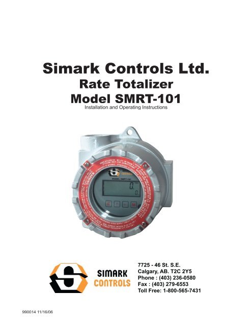
<strong>Simark</strong> <strong>Controls</strong> <strong>Ltd</strong>.<br />
Rate Totalizer<br />
Model SMRT-101<br />
Installation and Operating Instructions<br />
7725 - 46 St. S.E.<br />
Calgary, AB. T2C 2Y5<br />
Phone : (403) 236-0580<br />
Fax : (403) 279-6553<br />
Toll Free: 1-800-565-7431<br />
990014 11/16/06
CONTENTS<br />
Specifi cations ................................................................... 1<br />
Battery Installation and Replacement .............................. 3<br />
Dimensions ....................................................................... 4<br />
Theory of Operation .......................................................... 5<br />
Wiring ............................................................................... 5<br />
Typical Applications .......................................................... 5<br />
RS-485 Wiring .................................................................. 6<br />
Defi nitions ......................................................................... 7<br />
Programming Flowchart ................................................... 10<br />
Operation .......................................................................... 13<br />
Error Messages ................................................................ 14<br />
Analog Output Calibration ................................................ 14<br />
K-Factor Calculations ....................................................... 15<br />
Liquid Flowmeter Calculations .......................................... 15<br />
Warranty ........................................................................... 16<br />
Apendix A - Modbus RTU Protocol ................................... 16
SPECIFICATIONS<br />
Description<br />
Featuring 5 digits of rate and 8 digits of total, the SMRT-101 is a<br />
battery or loop powered indicator capable of accepting magnetic<br />
pickup, DC pulse or switch closure inputs from pulse producing<br />
fl owmeters. The unit offers a 4-20mA output. The SMRT-101 uses<br />
the 4-20mA loop to provide power when this output is used. Can be<br />
ordered with or without optional Modbus RTU protocol.<br />
Specifications<br />
Power:<br />
BATTERY POWERED<br />
Supplied with 1 C size Lithium battery.<br />
EXTERNAL POWER INPUT<br />
Voltage: 8.5 to 30 VDC<br />
Current: Less than 5 mA<br />
Supplied with 1 C size lithium battery.<br />
Protection: Reverse Polarity Protection on DC Power Input<br />
LOOP POWERED<br />
Voltage: 8.5 to 30 VDC<br />
Supplied with 1 C size lithium battery (battery needed for display)<br />
Protection: Reverse Polarity Protection on Current Loop<br />
PULSE OUTPUT:<br />
The pulse output advances with the least signifi cant digit of the<br />
totalizer or decimal multiples there of (see Pulse scale divider).<br />
Type: Isolated photomos relay<br />
Max. voltage (off state): 30 VDC<br />
Current (on state): 100mA<br />
Pulse Duration: Selectable 0.5, 0.25, 0.125, 0.0625 seconds<br />
Pulse Scale divider (Pulscale): User selectable, ÷1, ÷10, ÷100<br />
or OFF NOTE: Select OFF for max. battery life.<br />
Loop Burden: 8.5V maximum<br />
BATTERY LIFE EXPECTANCY:<br />
Expected Years of Operation for SMRT-101 of various powering<br />
options at equipment duty cycles<br />
POWER<br />
RUN TIME<br />
Idle<br />
2hrs/day<br />
8hrs/day<br />
24hrs/day<br />
Battery 10 yrs 10 yrs 10 yrs 8.4 yrs<br />
Loop<br />
Indefi nite operation when externally powered<br />
NOTE: Battery shelf life is rated at 10 years by manufacturer<br />
Life expectancy based on rated battery capacity at 20°C<br />
The above table is shown with pulse output inactive. Use<br />
of pulse output shortens battery life.<br />
Example: A pulse output of 0.06 sec. duration, once per<br />
second, would derate the battery life by 20%.<br />
DISPLAY:<br />
Rate Display: (selectable decimal)<br />
5 Digits (99999), 0.35" High, Display updates once per second<br />
with battery power, 8X per second with DC or Loop power<br />
Rate Descriptors: /MIN, /HR, /DAY<br />
Min. Input Frequency: 0.01 Hz to 10 Hz (selectable delay of 0.1<br />
to 99.9 seconds)*<br />
Selectable Rate Display Damping<br />
Totalizer Display: (selectable decimal)<br />
8 Digits (99999999), 0.2" High<br />
Totalizer Descriptors: GAL, BBL, MCF, M3,<br />
Display is viewable from -22°F (-30°C) to + 158°F (70°C)<br />
Warning Displays: Low battery warning<br />
ACCURACY:<br />
0.01% Reading, ±1 count<br />
Temperature Drift: 50 ppm/°C Worst Case<br />
ENVIRONMENTAL:<br />
TEMPERATURE<br />
Maximum Temperature: + 158°F (70°C)<br />
HUMIDITY<br />
0 - 90% Noncondensing<br />
MOUNTING STYLE:<br />
Explosion Proof -<br />
Class I, Division I, Groups B, C & D<br />
Class II, Division I, Groups E, F & G<br />
NEMA 4X<br />
CSA Certification:<br />
Style 3 Enclosure with option CSA is Certifi ed Explosion Proof<br />
for:<br />
CSA for Canada and USA<br />
Class I Division 1 Groups B,C,D<br />
Class II Division 1 Groups E,F,G<br />
Class III<br />
Enclosure: Type 4X<br />
Maximum Ambient Temperature +70C<br />
Input: 8-30 Vdc, 4-20mA<br />
Output: 4-20 mA<br />
CAUTION; KEEP COVER TIGHT WHILE CIRCUITS ARE<br />
ALIVE, A SEAL SHALL BE INSTALLED WITHIN<br />
450mm (18 in) OF THE ENCLOSURE WHEN<br />
USED IN GROUP B ATMOSPHERES AND<br />
WITHIN 1.5m (5 ft) WHEN USED IN GROUP C<br />
ATMOSPHERE<br />
CAUTION; PLUG ANY UNUSED CONDUIT ENTRIES WITH<br />
A CERTIFIED CONDUIT PLUG<br />
AVERTIR; GARDER LA COUVERTURE TENDUE PENDANT<br />
QUE CIRCUITS SONT VIVANTS , UN CACHET<br />
SERA INSTALLE DANS 450 mm (18 dans) DE LA<br />
CLOTURE QUAND UTILISE DANS LES ATMO-<br />
SPHERES DE B DE GROUPE ET DANS 1.5m (5<br />
ft) QUAND UTILISE DANS L’ATMOSPHERE DE C<br />
DE GROUPE<br />
AVERTIR; BOUCHER LES ENTREES INUTILISEES DE<br />
CONDUIT AVEC UN BOUCHON DE CONDUIT<br />
CERTIFIE<br />
* Slow input pulse rates, large delay setting and internal math<br />
operations may delay the update rate of information.<br />
1
SPECIFICATIONS<br />
(continued)<br />
INPUTS:<br />
MAGNETIC PICKUP INPUT<br />
Frequency Range: 0 to 3500 Hz<br />
Trigger Sensitivity: 10 mV p-p<br />
Over Voltage Protected: ± 30 VDC<br />
OPTO-ISOLATED DC PULSE INPUT<br />
High (logic 1): 4-30 VDC<br />
Low (logic 0): Less Than 1 VDC<br />
Minimum Current: .5 mA<br />
Hysteresis: 0.4 VDC<br />
Frequency Range: 0 to 5 kHz<br />
Min. Pulse Width: 0.1 msec<br />
CONTACT CLOSURE INPUT (contact closure to common)<br />
Internal Pullup Resistor: 100 KΩ to +3.6 VDC<br />
High (logic 1): Open or 4-30 VDC<br />
Low (logic 0): Less Than .5 VDC<br />
Internal Switch Debounce Filter: 0 to 40 Hz<br />
NOTE: Sustained contact closure will shorten battery life.<br />
RESET INPUT (contact closure to common)<br />
Internal Pullup Resistor: 100 KΩ to +3.6 VDC<br />
High (logic 1): Open or 4-30 VDC<br />
Low (logic 0): Less Than .5 VDC<br />
Minimum On : 25 msec<br />
NOTE: Sustained contact closure will shorten battery life.<br />
K-FACTOR<br />
Range: 0.001 to 99999999<br />
Decimal Point Locations: XXXX.XXXX to XXXXXXXX<br />
ANALOG OUTPUT:<br />
Type: 4-20 mA follows rate display, Two wire hookup<br />
Accuracy: 0.025% Full Scale at 20° C<br />
Temperature Drift: 50 ppm/°C Typical<br />
Reverse Polarity Protected<br />
Update Rate: 8 times/second<br />
NOTE: The SMRT-101 uses the 4-20 mA loop power as its primary<br />
power source when this option is used. The batteries<br />
are still required for standby battery operation. (The<br />
batteries are needed to power the display.)<br />
DATA LOGGER:<br />
The Data Logger stores the totalizer to fl ash memory once every<br />
24 hours at the time you set. The data logger will store a maximum<br />
of 27 logs.<br />
DATA STORAGE:<br />
Setup Information: Stored in fl ash memory<br />
Totalizer: Stored in battery backed RAM but can be saved to<br />
fl ash memory by operator for recall after battery change out.<br />
RS-485 MODBUS (optional):<br />
The optional RS-485 card utilizes Modbus RTU protocol to access<br />
a variety of process parameters.<br />
10 Point Linearization<br />
This feature allows the user to enter 10 different frequencies<br />
with 10 different corresponding K-Factors to linearize non linear<br />
signals.<br />
2
BATTERY INSTALLATION and REPLACEMENT<br />
Battery Installation:<br />
All SMRT-101 models are shipped without the battery installed. This preserves battery life when the unit is not in<br />
service. When using external BATPACK, mount within 12" and plug connector into 3 position square posts (see<br />
Fig 1). Polarity is not a concern because center is common. (The battery is needed to power the display.)<br />
To install the battery, begin by locating the battery holder. The SMRT-101 requires open ing the enclosure cover and<br />
removing the SMRT-101 to expose the battery holder.<br />
The plus terminal of the battery is marked with a (+) symbol stamped into the battery holder. Be sure to install the<br />
battery correctly.<br />
Install battery to begin setup procedure. See Programming Flowchart to setup desired operating parameters.<br />
Battery Replacement:<br />
The SMRT-101 has a battery monitor feature which illuminates when the lithium battery volt age approaches its<br />
end of life. A descriptor, “BAT”, illuminates when the battery volt age falls below this predetermined value. The low<br />
battery detector operates correctly with all power options.<br />
The battery, should be replaced within several weeks of the fi rst occurrence of low battery warning, “BAT”. Left<br />
unattended, the unit may become inaccurate, cease to operate or malfunction.<br />
Before replacing the battery, Press the ← (left arrow) key to save the totalizer. The display will show "SAVE TOTAL".<br />
This will save the current total value and the total will resume from this value when the new battery is installed.<br />
NOTE: If the display starts to fl ash after the "SAvE totAL" message times out, press the "E" (enter) key. If the message<br />
"E FLASH" is displayed, then there was not enough power left to save the setup and totalizer to fl ash memory.<br />
At this point you must record the totalizer and setup information and re-enter the setup data after the new battery<br />
is installed.<br />
Install new battery(ies) as described above.<br />
Fig 1<br />
Rear View<br />
BATPACK<br />
Connector<br />
121110 9 8 7<br />
Battery<br />
6 5 4 3 2 1<br />
Jumper momentarily to reset unit to factory default values.<br />
3
DIMENSIONS<br />
To access terminals, unscrew cover and loosen 2 panel screws.<br />
Terminals are on bottom side of PC board.<br />
5.00<br />
(127)<br />
4.63<br />
(117)<br />
E M<br />
5/16<br />
3/4 NPT (2) HLS<br />
5.00<br />
(127)<br />
4.25<br />
(108)<br />
5.25<br />
(133)<br />
4
THEORY OF OPERATION<br />
Flow rate equation:<br />
Input Frequency<br />
Flow Rate Indication =<br />
x Time Scaler<br />
FAC<br />
Where Time Scaler is equal to: 60 for rate per minute read out<br />
3600 for rate per hour read out<br />
86400 for rate per day read out<br />
Flow total equation:<br />
Flow Total<br />
=<br />
Sum of Input Pulses<br />
FAC<br />
10 Point Linearization:<br />
A 10 point linearization table is used to construct a curve<br />
describing the relationship of K-Factor and input frequen<br />
cy. The measured input frequency is used to ac cess<br />
the table. A linear interpolation of adjacent point pairs<br />
is used to arrive at the K-Factor at that input frequency.<br />
The fl ow rate and total are then computed based upon<br />
the K-Factor for that measurement sample.<br />
NOTE: For best performance and resolution choose as<br />
many decimal places as possible in the K-Factor.<br />
Example: Enter a K-Factor of 1 as 1.000.<br />
24 VDC<br />
- Power +<br />
Supply<br />
-<br />
Analog<br />
Input Card<br />
+<br />
Input<br />
123456 Ground<br />
Remote<br />
Totalizer<br />
24 VDC<br />
- Power +<br />
Supply<br />
TYPICAL APPLICATIONS<br />
MAG INPUT / 4-20 mA LOOP POWERED / PULSE OUTPUT<br />
121110 9 8 7<br />
4-20mA (+) 12 1 Mag Input 1<br />
4-20mA (-) 11 2 Mag Input 2<br />
Opto Input (+) 10 3 Shield/Common<br />
Opto Input (-) 9 4 Reset Input<br />
Opto Out (+) 8 5 Contact Input<br />
Opto Out (-) 7 6 Common<br />
MAG INPUT / DC POWERED / PULSE OUTPUT<br />
121110 9 8 7<br />
6 5 4 3 2 1<br />
6 5 4 3 2 1<br />
Turbine Meter with<br />
Mag Pickup<br />
WIRING<br />
Some typical applications of the SMRT-101 are shown<br />
at right. Please observe that the various pulse inputs and<br />
pow er options may be intermixed in many ways to solve<br />
com mon ap pli ca tions. The isolated pulse out put may be<br />
freely used so long as proper polarity is observed.<br />
Input<br />
123456 Ground<br />
Remote<br />
Totalizer<br />
4-20mA (+) 12 1 Mag Input 1<br />
4-20mA (-) 11 2 Mag Input 2<br />
Opto Input (+) 10 3 Shield/Common<br />
Opto Input (-) 9 4 Reset Input<br />
Opto Out (+) 8 5 Contact Input<br />
Opto Out (-) 7 6 Common<br />
Turbine Meter with<br />
Mag Pickup<br />
Caution: When 4-20 mA loop is used, the power wiring<br />
to the loop power should always be to ter mi nals<br />
(+) 12 and (-) 11. Ac ci den tal wiring to (+) 12 and<br />
(-)6 should be avoided since excessive current<br />
fl ow may result.<br />
MAG INPUT / BATTERY POWERED / PULSE OUTPUT<br />
Caution: The magnetic pickup input and contact clo sure<br />
input require isolated sensors for prop er oper<br />
a tion. Ac ci den tal connections to earth may<br />
result in er ro ne ous op er a tion of the analog<br />
output and/or ex ces sive cur rent fl ow.<br />
Caution: Accidental connections from circuit com mon (3<br />
or 6) to earth or terminal (11) may result in erroneous<br />
operation of the an a log output and/or<br />
excessive cur rent fl ow.<br />
Input<br />
123456 Ground<br />
Remote<br />
Totalizer<br />
121110 9 8 7<br />
6 5 4 3 2 1<br />
4-20mA (+) 12 1 Mag Input 1<br />
4-20mA (-) 11 2 Mag Input 2<br />
Opto Input (+) 10 3 Shield/Common<br />
Opto Input (-) 9 4 Reset Input<br />
Opto Out (+) 8 5 Contact Input<br />
Opto Out (-) 7 6 Common<br />
Turbine Meter with<br />
Mag Pickup<br />
5
RS-485 Terminals<br />
CA-285 Terminals<br />
18<br />
17<br />
16<br />
Ground (-)<br />
No Connection<br />
120KΩ Termination Resistor<br />
2<br />
3<br />
4<br />
5<br />
7<br />
6<br />
8<br />
20<br />
TD<br />
RD<br />
RTS<br />
CTS<br />
GND<br />
DSR<br />
DCD<br />
DTR<br />
DTE<br />
DCE<br />
TD<br />
RD<br />
T<br />
E<br />
R<br />
M<br />
I<br />
N<br />
A<br />
L<br />
5<br />
4<br />
3<br />
2<br />
1<br />
G<br />
R -<br />
R +<br />
T -<br />
T +<br />
15 Tx/Rx (-)<br />
14 Tx/Rx (+)<br />
13 DCV (+) 5-28 Volts<br />
RS-485 Terminal Block<br />
Switch Settings<br />
Switch<br />
Setting<br />
1 ON<br />
2 OFF<br />
3 OFF<br />
4 ON<br />
5 OFF<br />
Typical Hookup<br />
SMRT-101<br />
Unit 2<br />
SMRT-101<br />
Unit 1<br />
(+)<br />
115 VAC<br />
18<br />
17<br />
18<br />
17<br />
(–)<br />
24 VDC<br />
Power Supply<br />
16<br />
16<br />
15<br />
15<br />
14<br />
13<br />
Connect 16 to 14<br />
for optional<br />
Terminating Resistor<br />
14<br />
13<br />
G<br />
R -<br />
R +<br />
T -<br />
T +<br />
Model<br />
CA285<br />
CA285<br />
Power Adaptor<br />
115 VAC<br />
PC with<br />
RS-232 Port<br />
6
DEFINITIONS<br />
Save Total: (Save Total) Press the E key while the unit is running to save the total value. The display will show<br />
"save total" for a few seconds. This is a very useful "scratch pad" to save and restore total when replacing<br />
the battery(ies)<br />
ent Code: (enter code) This prompt will only appear if the panel lock is ON. Press the ↑ key to increment each digit.<br />
Press the ← key to step to the next digit to the left. Press the E key to enter the 5 digit code. If the entered<br />
code is correct, the display will advance to the next menu prompt (CLr tot). If incorrect, the display will return<br />
to the run mode.<br />
Clr tot: (clear total) Clears (resets) the totalizer. Press the E key to clear the total and return to the run mode. Press<br />
the M key to skip and advance to the next menu selection.<br />
fdeC: (factor decimal) Sets the decimal location for the factor. This location is restricted to 3 places (99.999). The use<br />
of this decimal automatically limits the number of decimal locations allowable in the rate and total to acceptable<br />
ranges. Press the ← key to move the decimal. Press the E key to select the displayed decimal location.<br />
NOTE: For best performance and resolution choose as many decimal places as possible in the K-Factor.<br />
Example: Enter a K-Factor of 1 as 1.000.<br />
faC lInear/10poInt: (factor type) This prompt will only appear if the unit is ordered with the 10 point linearization option.<br />
The 10 poInt linearization selection is recommended for flow meters whose K-factors change with different<br />
flow rates. This selection allows users to enter up to 10 different frequencies with 10 corresponding K-factors for<br />
different fl ow rates. The lInear setting is used for fl ow meters whose output is linear over its' entire operating<br />
fl ow range. Press the ↑ key to step to the desired choice. Press the E key to enter the displayed factor type.<br />
No / yes set Pnts: (set 10 point) This prompt allows the user to skip the 10 point setup routine. Select yes for<br />
initial setup or to change the present 10 point values. Select No to skip and keep the existing values.<br />
faC : (factor) This prompt appears on all units with linear inputs. The Factor is the number of pulses per unit volume<br />
for the fl ow sensor. The pulses/unit volume is implied by the totalizer descriptor when a descriptor is used. The<br />
implied units for the Factor are then as follows:<br />
Standard "D" Option<br />
GAL pulses/gallon GAL pulses/gallon<br />
LIT pulses/liter BBL pulses/BBL<br />
FT3 pulses/ft3 MCF pulses/MCF<br />
M3 pulses/M3 M3 pulses/M3<br />
Factors from 0.0001 to 99999999 may be used. A "0" value for the factor is not allowed and the unit will default<br />
to "1" in LSD if a "0" entry is attempted . The factor is displayed on the subsidiary (lower) display. Press the ↑<br />
key to increment each digit. Press the ← key to step to the next digit to the left. Press the E key to enter the<br />
displayed factor.<br />
fr# : (frequency for point #) This prompt will only appear when 10 point selected. It sets the frequency for each of<br />
the 10 points (#). Press the ↑ key to increment each digit. Press the ← key to step to the next digit to the left.<br />
Press the E key to enter the desired frequency for point #.<br />
faC# : (factor for point #) This prompt will only appear when 10 point selected. It sets the factor for each of the 10<br />
points (#). Press the ↑ key to increment each digit. Press the ← key to step to the next digit to the left. Press<br />
the E key to enter the desired factor for point #.<br />
NOTE: The display will advance to the next point (Fr#) after each entry of the Fr & Fac until all 10 points are complete.<br />
entering a 0 in the Fr or fac setting will advance the display to the next menu prompt (tdec).<br />
7
DEFINITIONS<br />
(continued)<br />
tdeC: (totalizer decimal) Sets the decimal location for the totalizer. The totalizer decimal is not a dummy decimal<br />
and will scale the totalizer display accordingly. (i.e. if the tdec is set in the tenths position (1234567.8), 100 will be<br />
displayed as 100.0). The location of the decimal point allows for greater resolution of both the totalizer display<br />
and the pulse output. The pulse output advances at a rate dependent on the least signifi cant digit of the totalizer.<br />
The totalizer decimal location is restricted to a maximum of 4 places (1234.5678). However, the number<br />
of totalizer decimal locations allowable is reduced with each decimal place added to the factor decimal. Press<br />
the ← key to move the decimal. Press the E key to enter the displayed decimal location.<br />
Note: The selection of the factor decimal point limits the available selections for the number of decimal<br />
points available for the totalizer. This is automatic. Enter your selection of the Factor’s decimal point<br />
before entering the totalizer decimal point to assure the proper selection of the totalizer decimal<br />
point has been made.<br />
tot desC: (totalizer descriptor) This allows you to illuminate one of the available descriptors on the display (STD:<br />
GAL, LIT, FT3, M3 or "blank"; "D" option: GAL, BBL, MCF, M3, "blank"). Press the ↑ key to select the descriptor.<br />
Press the E key to enter the selected descriptor.<br />
r sCale: (ratemeter scaling) Sets the timebase for the rate readout. Choose rate per hour (Hrs), minutes (nnIn)<br />
or seconds (seC). (Days will appear on units ordered with the "D" (rate per day) option.) The scale setting is<br />
shown on the main (upper) display. Press the ↑ key to step to the desired choice. Press the E key to enter the<br />
displayed scale setting.<br />
Note: A rate descriptor corresponding to the above choice will be illuminated on the display.<br />
r deCloC: (ratemeter decimal location) Sets the decimal location for the ratemeter information. The ratemeter decimal<br />
is not a dummy decimal and will scale the rate display accordingly. (i.e. if the r decloc is set in the tenths<br />
position (123.4), 100 will be displayed as 100.0). The ratemeter decimal location is restricted to a maximum of<br />
4 places (.1234). However, the number of ratemeter decimal locations allowable is reduced with each decimal<br />
place added to the factor decimal. Press the ← key to move the decimal. Press the E key to enter the displayed<br />
decimal location.<br />
Note: The fl ow rate indicator will fl ash “99999” if the computed fl ow rate exceeds the 99999<br />
display capability of the indicator. Choose a new decimal point location to avoid this.<br />
NOR# NORMALIZING FACTOR - Normalizes (averages or dampens) the fl ow rate data being received. Enter a<br />
value from 0 to 9. Higher settings provide more normalizing (averaging) for a more stable display. Derived<br />
from the equation:<br />
(Old Data x "NOR" + New Data)<br />
("NOR" + 1)<br />
delay: (delay) Sets the amount of time (0.1 to 99.9 seconds) that the unit will "look" for valid input data. If pulses<br />
are not detected within this "window", the rate will display 0. The display will update once every second as<br />
long as the unit receives valid data within a second. Some internal mathematics may delay this update.<br />
Press the ↑ key to increment each digit. Press the ← key to step to the next digit to the left. Press the E key<br />
to enter the displayed delay value.<br />
oUt lo: (out low) Sets the low setting for the 4-20 mA analog output. Key in the low rate value at which the unit will<br />
output 4mA. Press the ↑ key to increment each digit. Press the ← key to step to the next digit to the left. Press<br />
the E key to enter the displayed out lo value.<br />
oUt HI: (out high) Sets the high setting for the 4-20 mA analog output. Key in the high rate value at which the unit<br />
will output 20 mA. Press the ↑ key to increment each digit. Press the ← key to step to the next digit to the left.<br />
Press the E key to enter the displayed out hi value.<br />
8
DEFINITIONS<br />
(continued)<br />
pUlscale: (pulse out scaling) This allows the unit to output a pulse for each least signifi cant total count divided by<br />
the selected divider. The pulse out can be divided by 1 (d 1), 10 (d 10), 100 (d 100), or turned off (off). With<br />
the divider set at 1, the unit will give a pulse out for every increment of the LSD displayed.<br />
Note: For maximum battery life, turn the pulse output off when pulse output is not used.<br />
Selecting the proper pulse output divider may be needed so that the pulse output<br />
does not exceed the maximum rate of the pulse output. If the pulse output<br />
pulses too quickly a fl ashing display will result. Pressing the “M” key will result in a display of an error message<br />
“E PULSE”. Press the “E” key to return to the run mode.<br />
P uuidth: (pulse width) Sets the pulse width of the pulse output. Selections are: 0.5 (1Hz), 0.25 (2Hz),0.125 (4Hz)<br />
or 0.0625 (8Hz). This menu item is skipped if pUlscale is turned off.<br />
AddrESS: (address) Sets the address of the device from 1 to 247 for Modbus network. (Note: RS485 option)<br />
bAudrAtE: (baud rate) Sets the baud rate for the serial communication. (Note: RS485 option)<br />
Parity: (parity) Sets the parity for the serial communication. (Note: RS485 option)<br />
StoPbitS: (stop bits) Sets the number of stop bits for the serial communication. This menu item is skipped if Parity<br />
is nonE. (Note: RS485 option)<br />
trAnSdly: (transmission delay) A delay can be added between the time the SMRT-101 receives a request and when<br />
it responds to it (Note: RS485 option)<br />
dAtE: (date) Sets the date for the real time clock. The format is MMDDYYYY.<br />
timE: (time) Sets the time for the real time clock. The format is HHMM .<br />
Log t: (log time) Sets the time of day that the data logger will record the total.<br />
ViEuuLog: (view log) Prompts user to view data logger. Select YES to view or NO to skip. When YES is selected<br />
for ViEuuLog. The display will show the date of the last log in month and day format MMDD. Use the "E" or "M"<br />
keys to view previous logs.<br />
Log Clr: (log clear) Prompts user to clear the data logger. Select YES if you want to clear else select no.<br />
loC Code: (lock code) Sets the 5 digit lock code to be entered when the unit prompts ent Code. This allows the user<br />
to gain access to the menu when the unit is locked. Press the ↑ key to increment each digit. Press the ← key<br />
to step to the next digit to the left. Press the E key to enter the displayed code.<br />
Record this number for later use!<br />
LOCK CODE: ____________________<br />
loC UnIt: (lock unit) Sets the panel lock ON or OFF. Press the ↑ key to select On or OFF. Press the E key to enter<br />
the displayed selection.<br />
9
PROGRAMMING FLOWCHART<br />
RUN MODE<br />
ENTER CODE<br />
If panel<br />
lock OFF<br />
RATE<br />
TOTAL<br />
M<br />
If panel<br />
lock ON<br />
0000<br />
ent Code<br />
E<br />
If code<br />
correct<br />
If code<br />
incorrect<br />
Press the M key to enter the programming menu.<br />
If the panel lock is on, you must enter the 4 digit lock code to gain access<br />
to the menu.<br />
Press the key to increment each individual digit of the code.<br />
Press the key to advance to the next digit.<br />
Press the E key to enter the displayed code.<br />
If the code is correct, display advances to "clr tot", if not, display returns<br />
to run mode<br />
CLEAR TOTAL<br />
FACT<br />
OR<br />
DECIMAL<br />
CLR ToT<br />
M<br />
FDEC<br />
12345678<br />
M<br />
E<br />
E<br />
Press the E key to clear the totalizer and return to the programming<br />
menu.<br />
Press the M key to skip and go to next menu item.<br />
Press the key to step the factor decimal to the desired location.<br />
Press the E key to enter the displayed decimal location.<br />
Press the M key to skip and keep the existing location<br />
NOTE: For best performance and resolution choose as many decimal places as<br />
possible in the K-Factor.Example: Enter a K-Factor of 1 as 1.000.<br />
FACT<br />
OR<br />
TYPE<br />
10poInt<br />
lInear<br />
FAC<br />
10poInt<br />
M<br />
E<br />
Press the key to choose factor type (10point or linear).<br />
Press the E key to enter the displayed factor type.<br />
Press the M key to skip and keep the existing factor type.<br />
SET<br />
10PT<br />
YES<br />
No<br />
No<br />
selected<br />
10poInt<br />
selected<br />
YES<br />
SET pnts<br />
M<br />
FACT<br />
OR<br />
E<br />
YES<br />
selected<br />
lInear<br />
selected<br />
FAC<br />
M<br />
100<br />
E<br />
The FAC prompt will only appear if linear is selected.<br />
Press the key to increment each individual digit of the factor.<br />
Press the key to advance to the next digit.<br />
Press the E key to enter the displayed factor.<br />
Press the M key to skip and keep the existing factor.<br />
The SET pnts prompt will only appear if 10point is selected. This allows<br />
users to bypass the 10 point set up and keep the existing values.<br />
Press the key to choose YES or NO.<br />
Press the E key to enter the displayed selection.<br />
Press the M key to skip (same as selecting NO).<br />
FREQUENCY<br />
for POINT #<br />
(Fr0-Fr9)<br />
FACT<br />
OR for<br />
POINT #<br />
(FAC0-F<br />
AC0-FAC9)<br />
AC9)<br />
If Fr1-FR9 = 0<br />
Fr#<br />
#####<br />
M<br />
FaC#<br />
#####<br />
M<br />
# = 9<br />
E<br />
Continue On<br />
Next Page<br />
E<br />
Press the key to increment each individual digit of the frequency for<br />
point #.<br />
Press the key to advance to the next digit.<br />
Press the E key to enter the displayed frequency.<br />
Press the M key to skip and keep the existing frequency.<br />
If 0 is entered, the display will advance to the next prompt (tdec).<br />
NOTE: Frequency/factor point pairs must be entered in ascending order of frequency<br />
Press the key to increment each individual digit of the factor for point<br />
#.<br />
Press the key to advance to the next digit.<br />
Press the E key to enter the displayed factor.<br />
Press the M key to skip and keep the existing factor.<br />
If 0 is entered, the display will advance to the next prompt (tdec).<br />
10
TOTAL DECIMAL<br />
Continued From Previous Page<br />
TDEC<br />
12345678<br />
M<br />
PROGRAMMING FLOWCHART<br />
(continued)<br />
E<br />
Press the key to step the totalizer decimal to the desired location.<br />
Press the E key to enter the displayed decimal location.<br />
Press the M key to skip and keep the existing location<br />
TOTAL<br />
DESCRIPTOR<br />
GAL<br />
BBL<br />
FT3<br />
MFC<br />
"blank"<br />
ToT DESC<br />
M<br />
E<br />
Press the key to step to the desired totalizer descriptor.<br />
Press the E key to enter the displayed descriptor.<br />
Press the M key to skip and keep the existing descriptor.<br />
SCALE<br />
(ratemeter)<br />
NNIN<br />
HRS<br />
Days<br />
Hrs<br />
r SCALE<br />
E<br />
Press the key to step to the desired scale setting.<br />
Press the E key to enter the displayed scale setting.<br />
Press the M key to skip and keep the existing setting.<br />
M<br />
RATE<br />
DECIMAL<br />
LOCATION<br />
1234<br />
R DECLoC<br />
M<br />
E<br />
Press the key to step the ratemeter decimal to the desired location.<br />
Press the E key to enter the displayed decimal location.<br />
Press the M key to skip and keep the existing location<br />
NORMALIZATION<br />
1<br />
nor<br />
E<br />
Press the key to increment each individual digit of the "nor" factor.<br />
Press the E key to enter the displayed value.<br />
Press the M key to skip and keep the existing value.<br />
M<br />
DELAY<br />
(Dampening)<br />
0.1 to 99.9<br />
0.1<br />
delay<br />
M<br />
E<br />
Press the key to increment each individual digit of the delay.<br />
Press the key to advance to the next digit.<br />
Press the E key to enter the displayed value.<br />
Press the M key to skip and keep the existing value.<br />
OUT LOW<br />
(4mA)<br />
0000<br />
oUT Lo<br />
M<br />
E<br />
Press the key<br />
to increment each individual digit of the out low setting (4mA<br />
value). This will only display on units with Analog Output.<br />
Press the key to advance to the next digit.<br />
Press the E key to enter the displayed value.<br />
Press the M key to skip and keep the existing value.<br />
OUT HIGH<br />
(20mA)<br />
99999<br />
oUT HI<br />
M<br />
E<br />
Press the key to increment each individual digit of the out high setting<br />
(20mA value). This will only display on units with Analog Output.<br />
Press the key to advance to the next digit.<br />
Press the E key to enter the displayed value.<br />
Press the M key to skip and keep the existing value.<br />
PULSE<br />
SCALER<br />
(divider)<br />
D 1<br />
D 10<br />
D100<br />
oFF<br />
D 1<br />
Pul scale<br />
M<br />
E<br />
Press the key to step to the desired pulse scale divider for the pulse output.<br />
Press the E key to enter the displayed pulse scale divider.<br />
Press the M key to skip and keep the existing pulse scale value.<br />
PULSE<br />
WIDTH<br />
(seconds)<br />
.5<br />
.25<br />
.125<br />
.0625<br />
.5<br />
p uuidth<br />
M<br />
E<br />
Press the key to step to the desired pulse width for the pulse output.<br />
Press the E key to enter the displayed pulse width.<br />
Press the M key to skip and keep the existing pulse width.<br />
This will not display if Pulse Out is turned OFF.<br />
Continue On<br />
Next Page<br />
11
ADDRESS<br />
Continued From Previous Page<br />
001<br />
to<br />
247<br />
001<br />
address<br />
M<br />
E<br />
Press the key to increment each individual digit of the address.<br />
Press the key to advance to the next digit.<br />
Press the E key to enter the displayed value.<br />
Press the M key to skip and keep the existing value.<br />
BAUD RATE<br />
9600 600<br />
4800 300<br />
2400 110<br />
1200 off<br />
9600<br />
baudrate<br />
M<br />
E<br />
Press the key to select the desired baud rate.<br />
Press the E key to enter the displayed choice.<br />
Press the M key to skip and keep the existing choice.<br />
PARITY<br />
STOP BITS<br />
(only shows if<br />
parity = none)<br />
odd<br />
even<br />
none<br />
1<br />
2<br />
none<br />
parity<br />
M<br />
1<br />
stopbits<br />
M<br />
E<br />
E<br />
Press the key to select the desired parity.<br />
Press the E key to enter the displayed choice.<br />
Press the M key to skip and keep the existing choice.<br />
Press the key to select the desired number of stop bits.<br />
Press the E key to enter the displayed choice.<br />
Press the M key to skip and keep the existing choice.<br />
NOTE: Only appears if parity = none<br />
Transmission<br />
Delay<br />
0.0<br />
to<br />
1.0<br />
0.0<br />
transdl<br />
y<br />
M<br />
E<br />
Press the key to increment each individual digit of the trans. delay.<br />
Press the key to advance to the next digit.<br />
Press the E key to enter the displayed value.<br />
Press the M key to skip and keep the existing value.<br />
DATE<br />
0101.2000<br />
to<br />
1231.2099<br />
date<br />
1027.2004<br />
M<br />
E<br />
Press the key to increment each individual digit of the date.<br />
Press the key to advance to the next digit.<br />
Press the E key to enter the displayed value.<br />
Press the M key to skip and keep the existing value.<br />
TIME<br />
00.00<br />
to<br />
23.59<br />
time<br />
13.59<br />
M<br />
E<br />
Press the key to increment each individual digit of the time.<br />
Press the key to advance to the next digit.<br />
Press the E key to enter the displayed value.<br />
Press the M key to skip and keep the existing value.<br />
LOG TIME<br />
00.00<br />
to<br />
23.59<br />
log t<br />
15.59<br />
M<br />
E<br />
Press the key to increment each individual digit of the log time.<br />
Press the key to advance to the next digit.<br />
Press the E key to enter the displayed value.<br />
Press the M key to skip and keep the existing value.<br />
VIEW LOG<br />
no<br />
yes<br />
no<br />
vieuulog<br />
M<br />
E<br />
Press the key and select "yes" to view log. Select "no" to skip.<br />
Press the E key to enter the displayed choice.<br />
Press the M key to skip.<br />
LOG DATE<br />
(date of last log)<br />
No<br />
selected<br />
YES<br />
selected<br />
02.22<br />
00000000<br />
M<br />
E<br />
The date of last log will be shown in the format (MM.DD) if "yes" was selected<br />
above.<br />
Press M or E to view previous logs and exit when the end of datalog is<br />
reached.<br />
LOG CLEAR<br />
no<br />
yes<br />
no<br />
log clr<br />
E<br />
Press the key and select "yes" to clear log. Select "no" to skip.<br />
Press the E key to enter the displayed choice.<br />
Press the M key to skip.<br />
M<br />
LOCK<br />
CODE<br />
0000<br />
loc code<br />
M<br />
E<br />
Press the key to increment each individual digit of the lock code.<br />
Press the key to advance to the next digit.<br />
Press the E key to enter the displayed value.<br />
Press the M key to skip and keep the existing value.<br />
TURN LOCK<br />
ON or OFF<br />
yes<br />
no<br />
yes<br />
loC UnIt<br />
M<br />
E<br />
Press the key to step to the desired lock setting.<br />
Press the E key to enter the displayed lock setting.<br />
Press the M key to skip and keep the existing setting.<br />
RUN MODE<br />
12
OPERATION<br />
A suitable pulse producing device or fl ow meter is wired to one of the three pulse inputs provided on the SMRT-101.<br />
Only one of these inputs is used in a given application. There are no connections to the two unused pulse inputs.<br />
Isolated magnetic pickups may be connected to terminals 1 and 2. Isolated contact closures may be connected to<br />
terminals 5 and 6. Any high level, DC pulse type may be connected to terminals 9(-) and 10(+).<br />
Power to the unit may be provided by the internal battery, external DC, or the current loop. In all cases, the internal<br />
battery will provide for continued operation in the event primary power is lost.<br />
Once properly wired, the operation of the SMRT-101 is automatic.<br />
The fl ow totalizer is updated once per second* with battery power, 8 times per second with DC or loop power. If no<br />
input counts are received the unit remains in a low power state to conserve power.<br />
The fl ow total may be cleared by the front panel switch sequence or by a contact closure on the remote reset terminal<br />
to circuit common.<br />
To reset the unit from the front panel, the following key sequence is required:<br />
Press M “CLr tot” will be displayed (if the panel lock is on, the display will prompt "ent code".<br />
Enter the proper code to advance to the clr tot prompt)<br />
Press E To clear the total. Unit will return to operation<br />
The fl ow rate indicator will measure the fl ow rate once every second* with battery power, 8 times per second with<br />
DC or loop power and display the fl ow rate.<br />
If the input pulses are not detected within the delay setting (0.1 to 99.9 seconds), a fl ow rate of 0 will be indicated.<br />
The analog output will be scaled based on the user selected zero and full scale and the measured fl ow rate. The<br />
analog output is updated at the same time as the rate display.<br />
The pulse output updates at the same rate as the total display in accordance with the instrument setup of pulse<br />
scaling.<br />
* Slow input pulse rates, large delay setting and internal math operations may delay the update rate of information..<br />
A faster update rate occurs when the unit is loop powered or externally powered.<br />
MAINTENANCE:<br />
The only scheduled maintenance for the SMRT-101 is periodic replacement of the battery. See Battery Installation<br />
and Replacement for details.<br />
KEYPAD OPERATION:<br />
M<br />
is used to (after verifi cation of the password) clear<br />
the total & enter the setup menus<br />
Note:<br />
1. See also setup mode for description of its operation<br />
2. See also Calibration Section for description of its Operation<br />
is used to force a Save of the total to fl ash memory<br />
prior to replacement of battery<br />
is used to enable the user to view the datalog of<br />
daily total readings by date<br />
Press once to be offered "View log"<br />
Press to change “NO” to “YES”<br />
Press either E or M to view up to 27 total readings<br />
from previous days until all items in the data log<br />
have been read (Note: the unit will return to displaying<br />
Rate and Total after 30 seconds automatically<br />
if no keys are pressed<br />
13
ERROR MESSAGES<br />
The SMRT-101 is provided with extensive self checking which assists the user in the location of setup entry errors<br />
and in reporting malfunctions or unusual operating conditions. When an error occurs, the display will fl ash. Press<br />
any key to see the error message corresponding to the error that has occurred. Press any key again to acknowledge<br />
the error. (If the error can be eliminated by a change of setup values, the unit will automatically advance to<br />
the MENU so that the appropriate setup changes can be made).<br />
Table - 2 illustrates the warning message, problem, and recommended corrective actions.<br />
Diagnostic Error Messages Table-2<br />
WARNING MESSAGE CAUSE CORRECTIVE ACTION<br />
RATE ER Rate Low set<br />
Set Rate Hi greater<br />
higher than Rate Hi<br />
than Rate Lo<br />
FAC ERR Factor = 0<br />
Set in correct Factor<br />
“BAT” Descriptor Low Battery Replace battery(ies)<br />
E total Total rollover<br />
None required<br />
E RATE Rate exceeds 99999<br />
Use lower rate dec point<br />
E pulse Pulse out Overfl ow<br />
Use different pulse scaler or<br />
totalizer decimal point<br />
E FLASH Save to fl ash<br />
Write down displayed total and<br />
memory failed<br />
setup values if you are changing<br />
the battery. If total wasn't saved,<br />
it will display an arbitrary total<br />
when new battery is installed. In<br />
this case, reset the total to 0 and<br />
check the setup information.<br />
ANALOG OUTPUT CALIBRATION<br />
CAUTION: Performing the analog output calibration will erase all programming values. Please record all<br />
programmed values before beginning the analog output calibration<br />
If the unit is equipped with the analog output option, the 4-20 mA has been accurately set to 4.000 and<br />
20.000 mA by the factory. No calibrationshould be required.<br />
The 4-20 mA output may be verifi ed periodically by installing a digital milliamp meter(DMM) in series with the<br />
analog output and simulating a full scale or over range fl ow rate.<br />
If the output is out of calibration, perform the following:<br />
Remove power and/or disconnect battery(ies). Hold down the scroll (↑) key and replace the battery. This will<br />
initiallize the unit and advance to the analog output calibration mode. Connect a DMM set to read current in series<br />
with a power supply (8.5 to 30 volts DC) to TB12 (+) and TB11 (–). The output should read 4.000 ma (± 0.005).<br />
If it does not, Adjust the numbers on the display up or down until the output reads 4.000 ma (± 0.005). Press the<br />
"E" key. The DMM should now read 20.000 ma (± 0.005). If it does not, Adjust the numbers on the display up or<br />
down until the output reads 20.000 ma (± 0.005). Press "E" and the unit will return to the "RUN" mode.<br />
14
K-Factor or Divisor Calculations<br />
The signal from the fl owmeter used with the SMRT-101 is amplifi ed and conditioned by the electronic circuitry.<br />
The K-Factor (the number of pulses per unit volume from the fl owmeter) is programmed into the SMRT-101. A<br />
divisor can also be used which is the K-Factor. By making continuous calculations based on number of stored<br />
pulses and the divisor, the SMRT-101 generates rate and total volume readings in the desired unit of measure.<br />
K-Factor<br />
The K-Factor is the meter manufacturers stated pulses/unit volume for the fl owmeter determined at the factory for<br />
each particular fl owmeter. This information is supplied by the meter manufacturer. The units of volume are stated.<br />
Divisor<br />
The divisor is the pulses per user unit of volume that is required in the setup of the instrument to provide indication<br />
in the desired user units of volume. The divisor is equal to (K-Factor x Volume Conversion Factor) and is entered<br />
by the user during the setup of the instrument.<br />
The following liquid fl owmeter examples will help you calculate divisors for the SMRT-101. To enter the data into<br />
the SMRT-101, follow the programming fl owcharts on pages 8 and 9.<br />
Liquid Flowmeter Calculations<br />
The divisor for a liquid fl owmeter is determined based on the fl owmeter calibration factor (K-Factor) and the appropriate<br />
conversion factor for the required units of measure. The following examples provide liquid fl owmeter<br />
calculations for barrels, gallons and cubic meters.<br />
Barrels<br />
To set the totalizer to display total barrels, multiply the pulses/gal (K-Factor) by 42 (gal/bbl).<br />
Examples:<br />
1 inch Turbine Meter calibration Factor (K-Factor) of 900 pulses/gal.<br />
To display in Total Barrels enter 37800. as the factor in the SMRT-101 (900 x 42 = 37800. pulses/bbl)<br />
1.5 inch Turbine Meter calibration factor (K-Factor) of 325 pulses/gal.<br />
To display in Total Barrels enter 13650. as the factor in the SMRT-101 (325 x 42 = 13650. pulses/bbl)<br />
NOTE:<br />
If the required totalizer display is in tenths of barrels, enter one decimal point at the tdec display when<br />
programming the SMRT-101. The SMRT-101 scales the display accordingly.<br />
Gallons<br />
To set the totalizer to display total gallons, simply enter the decimal in the desired location when the fdec is displayed<br />
and enter the K-Factor at the fac display that follows fdec. Gallons will totalled in the totalizer display.<br />
Examples:<br />
1 inch Turbine Meter calibration Factor (K-Factor) of 900 pulses/gal.<br />
To display in Total Gallons enter 900.0 as the factor in the SMRT-101<br />
1.5 inch Turbine Meter calibration factor (K-Factor) of 325 pulses/gal.<br />
To display in Total Gallons enter 325.00 as the factor in the SMRT-101<br />
NOTE: If the required totalizer display is in tenths of gallons, enter one decimal point at the tdec display when<br />
programming the SMRT-101. The SMRT-101 scales the display accordingly.<br />
15
Cubic Meters<br />
To set the totalizer to display total cubic meters, multiply the calibration factor (K-Factor) by 264.17.<br />
Examples:<br />
1 inch Turbine Meter calibration Factor (K-Factor) of 900 pulses/gal.<br />
To display in Total Cubic Meters enter 237753 as the factor in the SMRT-101 (900 x 264.17= 237753)<br />
1.5 inch Turbine Meter calibration factor (K-Factor) of 325 pulses/gal.<br />
To display in Total Cubic Meters enter 85855.25 as the factor in the SMRT-101 (300 x 264.17= 85855.25)<br />
NOTE:<br />
If the required totalizer display is in tenths of cubic meters, enter one decimal point at the tdec display when<br />
programming the SMRT-101. The SMRT-101 scales the display accordingly.<br />
Descriptors<br />
GAL, BBL, MCF, M3<br />
Descriptors that can be selected on the SMRT-101 are for display purposes only. Make sure the descriptor<br />
matches the desired volume units of display when you are programming the unit. To display other volume units,<br />
us the "blank" option.<br />
Rate<br />
/MIN, /HR, /DAY<br />
When a particular rate of display is selected, the display automatically calculates the rate depending on the selection.<br />
Volume per minute (/MIN), volume per hour (/HR) or volume per day (/DAY).<br />
WARRANTY<br />
This product (excluding batteries) is warranted against defects in materials<br />
and workmanship for a period of one (1) year from the date of shipment to<br />
Buyer.<br />
The Warranty is limited to repair or replacement of the defective unit at the<br />
option of the manufacturer. This warranty is void if the product has been<br />
altered, misused, dismantled, or otherwise abused.<br />
ALL OTHER WARRANTIES, EXPRESSED OR IMPLIED, ARE EXCLUDED,<br />
INCLUDING BUT NOT LIMITED TO THE IMPLIED WARRANTIES OF<br />
MERCHANTABILITY AND FITNESS FOR A PARTICULAR PURPOSE.<br />
16
Appendix A - Modbus RTU Protocol<br />
When the SMRT-101 is equipped with the Modbus option, the protocol it uses is the Modbus RTU protocol. This<br />
protocol defi nes a message structure that hosts and clients will recognize and use on the Modbus network over<br />
which they communicate. It describes the process a master device (PC compatible) uses to request access to<br />
another device (SMRT-101), how it will respond to requests from the other devices, and how errors will be<br />
detected and reported. It establishes a common format for the layout and contents of message fi elds. During<br />
communications on a Modbus RTU network, the protocol determines how each SMRT-101 will know its device<br />
address, recognize a message addressed to it, determine the kind of action to be taken, and extract any data or<br />
other information contained in the message. If a reply is required, the SMRT-101 will construct the reply message<br />
and send it using Modbus RTU protocol.<br />
RTU Mode<br />
The SMRT-101 with Modbus communications option supports the Modbus RTU (Remote Terminal Unit) mode<br />
only. The Modbus ASCII mode is not supported. The main advantage of the RTU mode is that its greater character<br />
density allows better data throughput than ASCII for the same baud rate. The Modbus RTU uses a Master-<br />
Slave Query-Response Cycle in which the SMRT-101 is the slave device.<br />
Control Functions<br />
The SMRT-101 with Modbus communications option supports the following function codes:<br />
CODE NAME DESCRIPTION<br />
01 Read Coil Status Reads the status of a coil (ON or OFF)<br />
03 Read Holding Registers Reads the value in a holding register<br />
05 Force Single Coil Forces a single coil (0x reference) to either ON or OFF<br />
06 Preset Single Register Presets a value into a single holding register (4x reference)<br />
15 Force Multiple Coil Forces each coil (0x reference) in a sequence of coils to either ON or<br />
OFF<br />
16 Preset Multiple Registers Presets values into a sequence of holding registers (4x reference)<br />
SMRT-101 Communication Setup Menu<br />
The setup menu allows Modbus RTU Protocol communications parameters of: Device ID, Baud Rate, and Parity<br />
to be selected to match the parameters of your Modbus network. Each SMRT-101 must have it’s own Device ID<br />
and the same Baud Rate and Parity setting.<br />
17
Register & Coil Usage<br />
Register Usage<br />
(each register is 2 bytes)<br />
Data<br />
Register<br />
Data Type<br />
Access<br />
Volume Flow Reg 40001 & 40002 Float Read<br />
Total Reg 40003 & 40004 Float Read<br />
Linear K-Factor Reg 40005 & 40006 Float Read/Write<br />
Frequency#0 Reg 40007 & 40008 Float Read/Write<br />
Factor#0 Reg 40009 & 40010 Float Read/Write<br />
Frequency#1 Reg 40011 & 40012 Float Read/Write<br />
Factor#1 Reg 40013 & 40014 Float Read/Write<br />
Frequency#2 Reg 40015 & 40016 Float Read/Write<br />
Factor#2 Reg 40017 & 40018 Float Read/Write<br />
Frequency#3 Reg 40019 & 40020 Float Read/Write<br />
Factor#3 Reg 40021 & 40022 Float Read/Write<br />
Frequency#4 Reg 40023 & 40024 Float Read/Write<br />
Factor#4 Reg 40025 & 40026 Float Read/Write<br />
Frequency#5 Reg 40027 & 40028 Float Read/Write<br />
Factor#5 Reg 40029 & 40030 Float Read/Write<br />
Frequency#6 Reg 40031 & 40032 Float Read/Write<br />
Factor#6 Reg 40033 & 40034 Float Read/Write<br />
Frequency#7 Reg 40035 & 40036 Float Read/Write<br />
Factor#7 Reg 40037 & 40038 Float Read/Write<br />
Frequency#8 Reg 40039 & 40040 Float Read/Write<br />
Factor#8 Reg 40041 & 40042 Float Read/Write<br />
Frequency#9 Reg 40043 & 40044 Float Read/Write<br />
Factor#9 Reg 40045 & 40046 Float Read/Write<br />
Rate Delay Reg 40047 & 40048 Float Read/Write<br />
Analog Out Low Reg 40049 & 40050 Float Read/Write<br />
Analog Out High Reg 40051 & 40052 Float Read/Write<br />
Flow Total Log #0 Reg 40053 & 40054 Float Read/Write<br />
Flow Total Log #1 Reg 40055 & 40056 Float Read/Write<br />
Flow Total Log #2 Reg 40057 & 40058 Float Read/Write<br />
Flow Total Log #3 Reg 40059 & 40060 Float Read/Write<br />
Flow Total Log #4 Reg 40061 & 40062 Float Read/Write<br />
Flow Total Log #5 Reg 40063 & 40064 Float Read/Write<br />
Flow Total Log #6 Reg 40065 & 40066 Float Read/Write<br />
Flow Total Log #7 Reg 40067 & 40068 Float Read/Write<br />
Flow Total Log #8 Reg 40069 & 40070 Float Read/Write<br />
Flow Total Log #9 Reg 40071 & 40072 Float Read/Write<br />
Flow Total Log #10 Reg 40073 & 40074 Float Read/Write<br />
Flow Total Log #11 Reg 40075 & 40076 Float Read/Write<br />
Flow Total Log #12 Reg 40077 & 40078 Float Read/Write<br />
Flow Total Log #13 Reg 40079 & 40080 Float Read/Write<br />
Flow Total Log #14 Reg 40081 & 40082 Float Read/Write<br />
Flow Total Log #15 Reg 40083 & 40084 Float Read/Write<br />
Flow Total Log #16 Reg 40085 & 40086 Float Read/Write<br />
Flow Total Log #17 Reg 40087 & 40088 Float Read/Write<br />
Flow Total Log #18 Reg 40089 & 40090 Float Read/Write<br />
Flow Total Log #19 Reg 40091 & 40092 Float Read/Write<br />
Flow Total Log #20 Reg 40093 & 40094 Float Read/Write<br />
Flow Total Log #21 Reg 40095 & 40096 Float Read/Write<br />
Flow Total Log #22 Reg 40097 & 40098 Float Read/Write<br />
Flow Total Log #23 Reg 40099 & 40100 Float Read/Write<br />
18
Register & Coil Usage (continued)<br />
Data<br />
Register<br />
Data Type<br />
Access<br />
Flow Total Log #24 Reg 40101 & 40102 Float Read/Write<br />
Flow Total Log #25 Reg 40103 & 40104 Float Read/Write<br />
Flow Total Log #26 Reg 40105 & 40106 Float Read/Write<br />
K-Factor Decimal Point Reg 40133 Integer Read/Write<br />
K-Factor Algorithm Reg 40134 Integer Read/Write<br />
Total Decimal Point Reg 40135 Integer Read/Write<br />
Total Descriptors Reg 40136 Integer Read/Write<br />
Rate Time scale Reg 40137 Integer Read/Write<br />
Rate Decimal Point Reg 40138 Integer Read/Write<br />
Rate Normalization Reg 40139 Integer Read/Write<br />
Pulse Scale Reg 40140 Integer Read/Write<br />
Device Address Reg 40141 Integer Read/Write<br />
Baud Rate Reg 40142 Integer Read/Write<br />
Parity Reg 40143 Integer Read/Write<br />
Lock Code Reg 40144 & 40145 Integer Read/Write<br />
Lock Unit Reg 40146 Integer Read/Write<br />
Current Year (YYYY) Reg 40147 Integer Read/Write<br />
Current Month (1-12) Reg 40148 Integer Read/Write<br />
Current Day (1-31) Reg 40149 Integer Read/Write<br />
Current Time Hr (00-23 24 Hr format) Reg 40150 Integer Read/Write<br />
Current Time Min (00-59) Reg 40151 Integer Read/Write<br />
Reading Time HH Hour (00-23) Reg 40152 Integer Read/Write<br />
Reading Time MM Minute (00-59) Reg 40153 Integer Read/Write<br />
NOTE: The Float data type follows the IEEE format for a 32 bit fl oat.<br />
COIL USAGE<br />
(each coil is 1 bit)<br />
Data Coil Data Type<br />
Access<br />
Error-Rate Overfl ow Coil 00001 bit Read<br />
Error-Pulse out Overfl ow Coil 00002 bit Read<br />
Error-Total rollover Coil 00003 bit Read<br />
Error-Flash problem Coil 00004 bit Read<br />
Total Reset Coil 00005 bit Write<br />
Clear Error Coil 00006 bit Write<br />
Clear Data Log Coil 00007 bit Write<br />
19


