Wiring Diagram - Appliance 911 Sea Breeze
Wiring Diagram - Appliance 911 Sea Breeze
Wiring Diagram - Appliance 911 Sea Breeze

You also want an ePaper? Increase the reach of your titles
YUMPU automatically turns print PDFs into web optimized ePapers that Google loves.
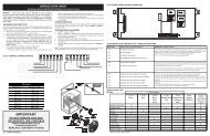
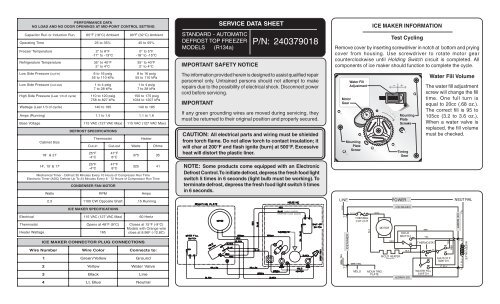
PERFORMANCE DATA<br />
NO LOAD AND NO DOOR OPENINGS AT MID-POINT CONTROL SETTING<br />
Capacitor<br />
Run or Induction Run<br />
65°F (18°C) Ambient<br />
90°F (32°C) Ambient<br />
O perating Time<br />
25<br />
to 35%<br />
45 to 55%<br />
Freezer<br />
Temperature<br />
Refrigerature<br />
Temperature<br />
L ow Side Pressure ( cut-in)<br />
L ow Side Pressure ( cut-out)<br />
H igh Side Pressure ( Last<br />
1/3 of cycle)<br />
2° to 8° F<br />
-17° to -13°C<br />
35° to 40° F<br />
2° to 4°C<br />
8 to 16 psig<br />
55 to 110 kPa<br />
1 to 4 psig<br />
7 to 28 kPa<br />
110 to 120 psig<br />
758 to 827 kPa<br />
0° to 5°F<br />
-18° to -15°C<br />
35° to 40°F<br />
2° to 4°C<br />
8 to 16 psig<br />
55 to 110 kPa<br />
1 to 4 psig<br />
7 to 28 kPa<br />
150 to 175 psig<br />
1034 to 1207 kPa<br />
Wattage<br />
(Last 1/3 of cycle)<br />
140<br />
to 185<br />
140 to 185<br />
Amps<br />
(Running)<br />
1.1<br />
to 1. 6<br />
1.1 to 1. 6<br />
B ase Voltage<br />
115<br />
VAC (127 VAC Max)<br />
115 VAC (127 VAC Max)<br />
Cabinet Size<br />
18' & 21'<br />
DEFROST SPECIFICATIONS<br />
Cut-in<br />
25°F<br />
-4°C<br />
Thermostat<br />
Cut-out<br />
47°F<br />
8°C<br />
Watts<br />
Heater<br />
Ohms<br />
375<br />
35<br />
STANDARD - AUTOMATIC<br />
DEFROST TOP FREEZER<br />
MODELS (R134a)<br />
SERVICE DATA SHEET<br />
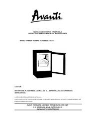
IMPORTANT SAFETY NOTICE<br />
The information provided herein is designed to assist qualified repair<br />
personnel only. Untrained persons should not attempt to make<br />
repairs due to the possibility of electrical shock. Disconnect power<br />
cord before servicing.<br />
IMPORTANT<br />
P/N: 240379018<br />
If any green grounding wires are moved during servicing, they<br />
must be returned to their original position and properly secured.<br />
CAUTION: All electrical parts and wiring must be shielded<br />
from torch flame. Do not allow torch to contact insulation; it<br />
will char at 200°F and flash ignite (burn) at 500°F. Excessive<br />
heat will distort the plastic liner.<br />
ICE MAKER INFORMATION<br />
Test Cycling<br />
Remove cover by inserting screwdriver in notch at bottom and prying<br />
cover from housing. Use screwdriver to rotate motor gear<br />
counterclockwise until Holding Switch circuit is completed. All<br />
components of ice maker should function to complete the cycle.<br />
Water Fill Volume<br />
The water fill adjustment<br />
screw will change the fill<br />
time. One full turn is<br />
equal to 20cc (.68 oz.).<br />
The correct fill is 95 to<br />
105cc (3.2 to 3.6 oz.).<br />
When a water valve is<br />
replaced, the fill volume<br />
must be checked.<br />
14', 15' & 17'<br />
25°F<br />
-4°C<br />
47°F<br />
8°C<br />
325<br />
41<br />
Mechanical Timer - Defrost 30 Minutes Every 10 Hours of Compressor Run Time<br />
Electronic Timer (ADC) Defrost Up To 24 Minutes Every 6 - 72 Hours of Compressor Run Time<br />
Watts<br />
CONDENSER FAN MOTOR<br />
RPM<br />
Amps<br />
NOTE: Some products come equipped with an Electronic<br />
Defrost Control. To initiate defrost, depress the fresh food light<br />
switch 5 times in 6 seconds (light bulb must be working). To<br />
terminate defrost, depress the fresh food light switch 5 times<br />
in 6 seconds.<br />
2.3<br />
1100<br />
CW Opposite Shaft<br />
.15 Running<br />
LINE<br />
POWER<br />
NEUTRAL<br />
Wire<br />
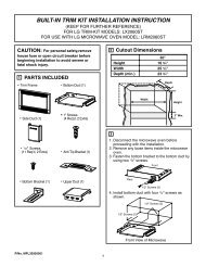
ICE MAKER CONNECTOR PLUG CONNECTIONS<br />
Number<br />
ICE MAKER SPECIFICATIONS<br />
E lectrical<br />
115<br />
VAC (127 VAC Max)<br />
60 Hertz<br />
T hermostat<br />
O pens at 48°F (9°C)<br />
Closes at 15°F (-9°C)<br />
Models with Orange wire<br />
Heater<br />
Wattage<br />
165<br />
close at 8.96F (-12.8C)<br />
1 Green/Yellow<br />
2 Yellow<br />
3 Black<br />
4 Lt.<br />
Blue<br />
W ire Color<br />
Connects to:<br />
Ground<br />
Water Valve<br />
Line<br />
Neutral<br />
(some models)<br />
ORANGE (some models)<br />
BLK<br />
GRN / YEL<br />
P-3<br />
ICE MAKER<br />
P-1<br />
BLK<br />
THER MAL<br />
CUT-OUT<br />
GRN / YEL<br />
MOL D<br />
BLK<br />
BRN<br />
MOUN TING<br />
PLATE<br />
MOTOR<br />
RED<br />
MOLD HEATER<br />
ICE MAKER<br />
HOLD<br />
SW ITCH<br />
BLK<br />
ICE MAKER<br />
YEL<br />
T HERMOSTAT<br />
WATER FILL<br />
SWITCH<br />
BLU<br />
SHUT-OF F<br />
SWITCH<br />
LT. B LU<br />
YEL<br />
RED<br />
ICE MAKER<br />
YEL<br />
P-4<br />
LT. BLU<br />
P-2<br />
WATER VALVE
Pictorial Schematic<br />
Ladder Schematic<br />
COMPRESSOR WIRING<br />
Induction Run Compressor with Relay